GS 608 Introduction to GPS Theory and Applications


 § Geographical (geometric) § Earth is projected into")


, centered at the center")


")

 or physically (Geoid)")


 has been established")
 is")

 based on the definition of WGS 84 ellipsoid")

 • The original WGS 84 reference frame established")
 Using GPS data from the Air Force and")
 Ø Within the past years, the coordinates for")
 Coordinates and WGS 84 (G 730), compared at")
 • The WGS 84 (G 730) reference frame")
 • The global geocentric reference frame and collection")
 •")
 NAD 27 established in 1927 Ø defined by ellipsoid that")


 and UTM Coordinate Zone")

")
 Ø Dynamic")


 (computed from a geoid model)")


, it is convenient")


 1985 Ø IGLD 85 • replaced earlier IGLD 1955")
 is very important Ø")
- Slides: 96
GS 608 Introduction to GPS: Theory and Applications Undergraduate and Graduate, 3 credit hours AU 2001 Department of Civil and Environmental Engineering and Geodetic Science
Part I SPATIAL REFRENCE SYSTEMS AND FRAMES GS 608 References: http: //www. geocities. com/Cape. Canaveral/1224/theory. html (and referenced links) http: //www. colorado. Edu/geography/gcraft/notes/datum_f. html
Now, where in the world am I?
Local and Global Ellipsoid
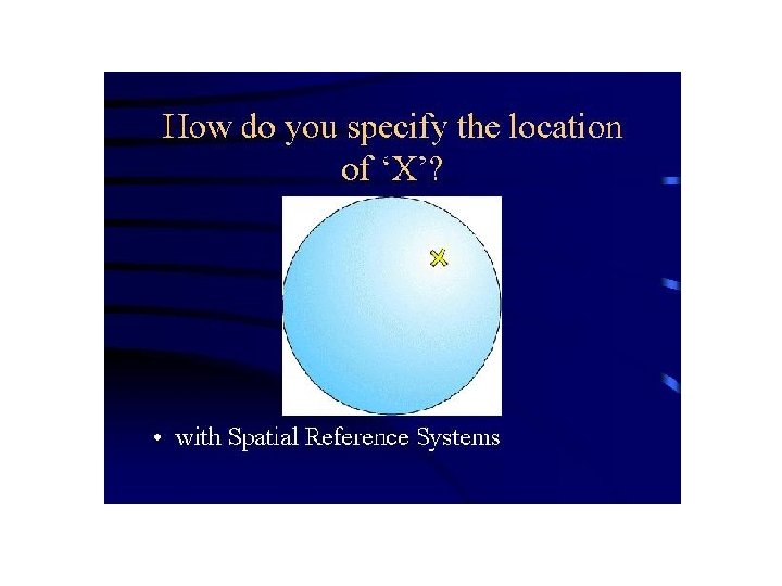
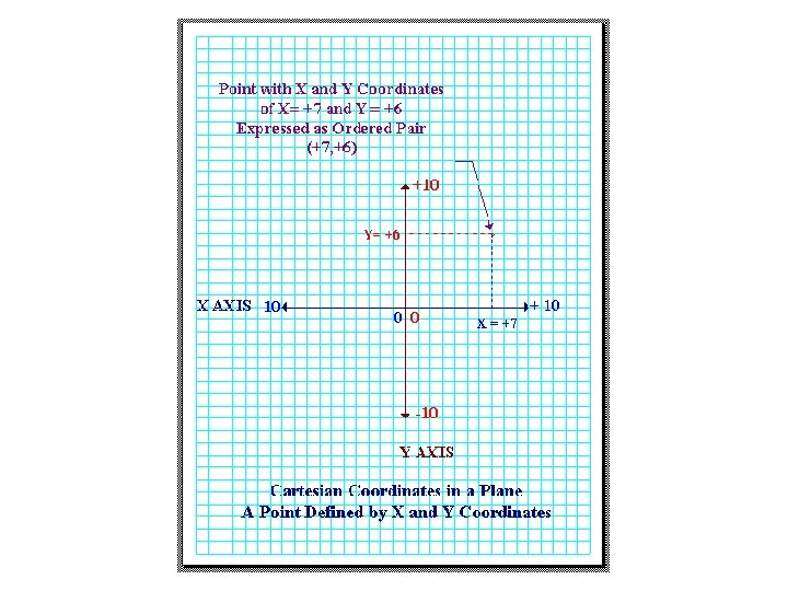
Ø Maps are 2 -dimensional abstractions of reality § As such, they are not located in their “real” geographic setting § They are removed from real coordinates Thus: § We must have a system for locating objects once they are depicted on a map, in geographic space § These systems are called Spatial Reference Systems
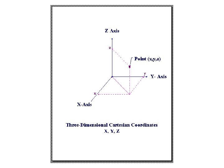
Ø Reference systems § Abstract (Cartesian) § Geographical (geometric) § Earth is projected into 2 -dimensional space § Or, can be viewed in 3 -dimensions
Grid can vary from map to map and make comparison between maps difficult
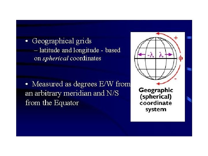
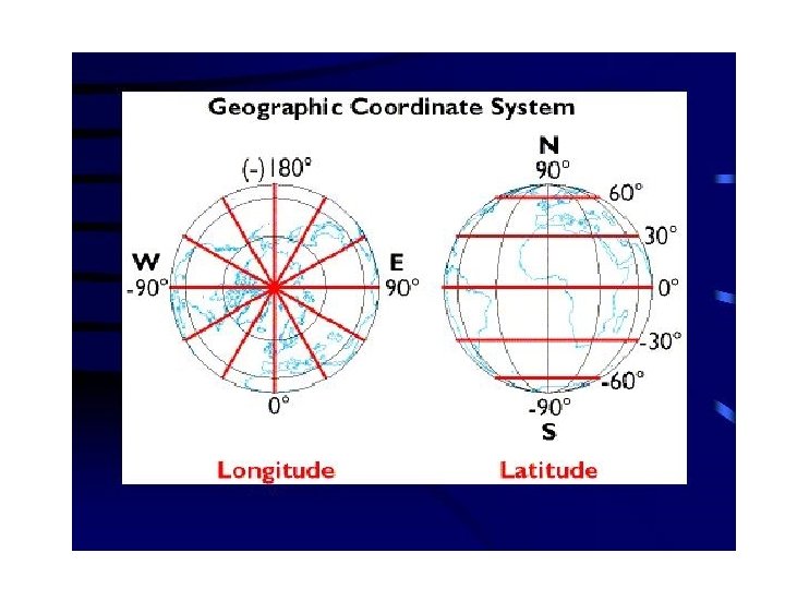
Sphere as an approximation of the Earth surface Geographical coordinates Latitude, longitude and height above the sphere (measured along the normal to the sphere)
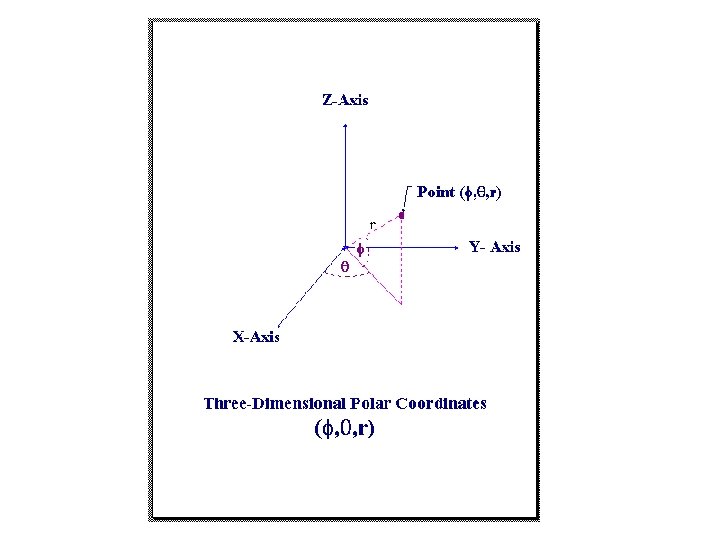
Point is located on the surface of the reference sphere • r is a radius of the reference sphere approximating the shape of the Earth • XYZ triad is placed at the center of the sphere For points with elevation h above the reference sphere:
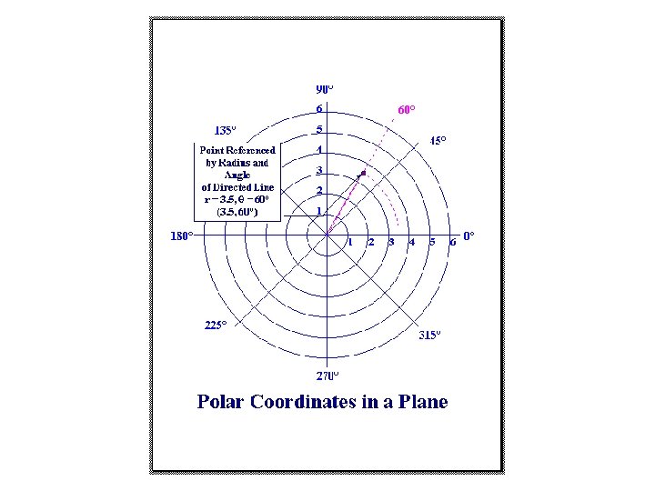
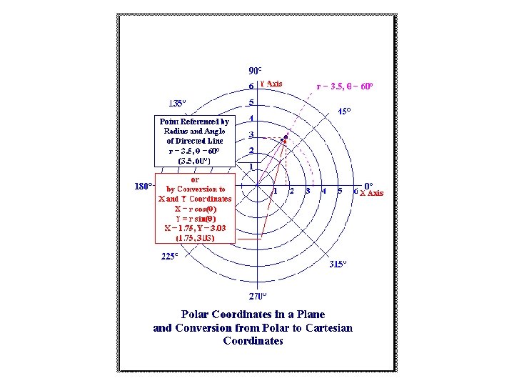
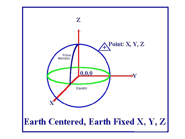
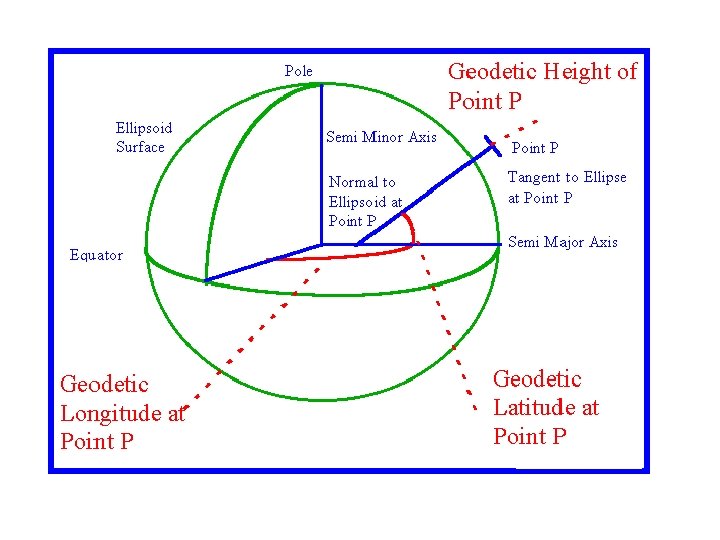
Ø If the triad XYZ is ECEF (Earth-centered and Earthfixed), centered at the center of mass of the reference sphere with radius r Ø And the plane XZ is located in the reference (zero) meridian plane Ø And the plane XY is located in the equatorial plane Ø The polar coordinates and can be referred to as geographical (spherical) coordinates, latitude and longitude.
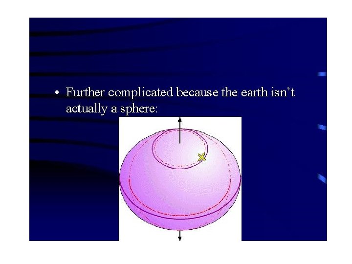
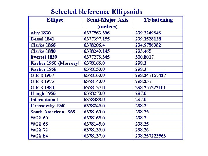
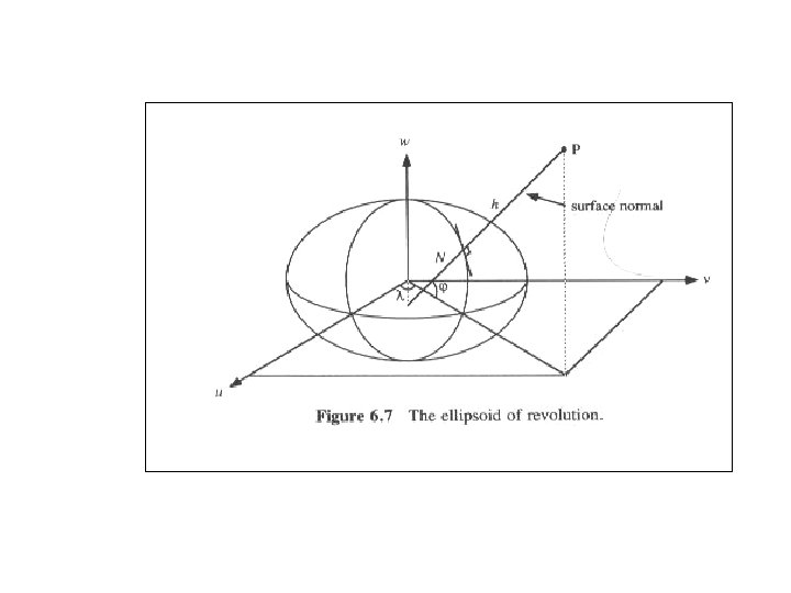
Ø Geographical coordinate systems § Based on spherical shape of the Earth Ø Geodetic coordinate systems § Based on ellipsoidal shape of the Earth § Varying systems use different reference ellipsoids (spheroids) § Ellipsoid is an approximation of the shape of the Earth: the Earth is an oblate ellipsoid, nearly spherical, but bulging at the equator.
Terminology confusion with geographic coordinates 3 types of co-ordinates define different perpendiculars: • astronomical coordinates physically defined perpendicular, based on the gravity • geodetic coordinates mathematically defined perpendicular, based on the reference surface, specifically ellipsoid, used for large and medium scale mapping, and in geodesy. • geographic coordinates mathematically defined perpendicular, based on the reference surface, typically spheres, used for small scale mapping
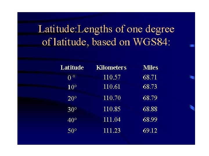
Spherical Coordinates Based on Ellipsoid of Revolution • They are consistent from map to map, but making measurements necessary to use them may be difficult as • degrees of longitude vary in distance from about 69 miles at the equator to 0 mile at the poles • Geodetic coordinates are not directly measurable in the field, they can be observed by astronomical methods and reduced to the ellipsoid
WGS 84
Coordinate Frame Geometry
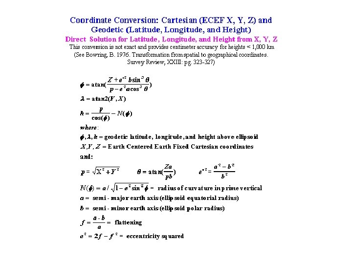
Coordinate Conversion: Cartesian X, Y, Z to Geodetic Lat, Lon, h v Precise (accurate) conversion can be performed Ø Iteratively • direct computation of longitude • iterate for latitude and height Ø Closed formulas (Borkowski, 1989; see the handout, IERS Conventions, 1996, p. 12)
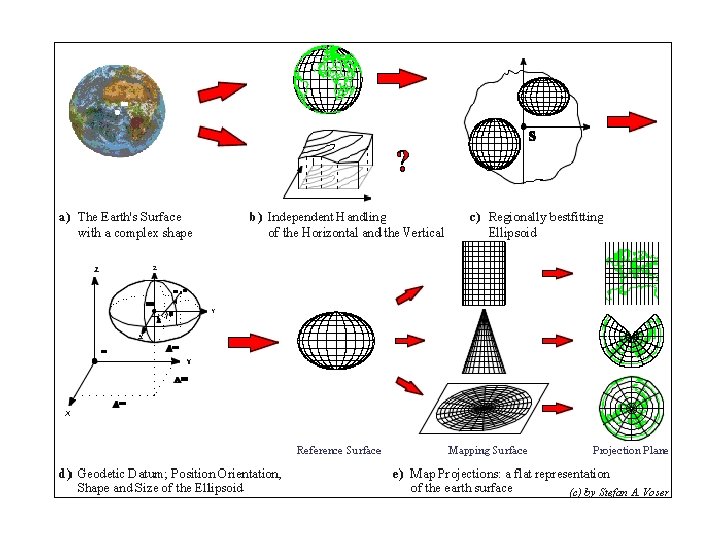
Short Definitions 1/2 Map Projection A Map Projection defines the mapping from geographic coordinates on a sphere or the geodetic coordinates on a spheroid to a plane. Reference System Shape, size, position and orientation of a (mathematical) Reference Surface, (e. g. Sphere or Spheroid). It normally is defined in a superior, geocentric three-dimensional coordinate system (for example WGS 84, ITRF).
Short Definitions 2/2 Reference Surface Mathematically (e. g. Sphere or Spheroid) or physically (Geoid) defined surface to approximate the shape of the earth for referencing the horizontal and/or vertical position. Reference Frame A set of control points to realize a Reference System. Geodetic Datum Traditional Term for Reference System.
Reference Systems: SUMMARY 1/2 • A coordinate system is most commonly referred to as three mutually perpendicular axes, scale and a specifically defined origin • An access to the coordinate system is provided by coordinates of a set of well defined reference points • Coordinate system and an ellipsoid create a datum; ellipsoid must be defined by two parameters (a and f or a and e); ellipsoid must be oriented in space • Modern systems, especially these derived from GPS observations are Earth-centered, Earth-fixed (ECEF)
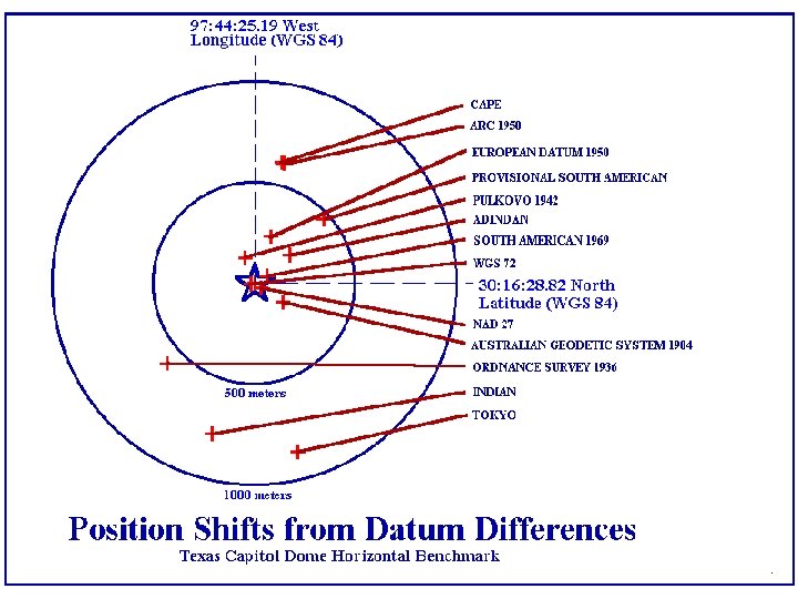
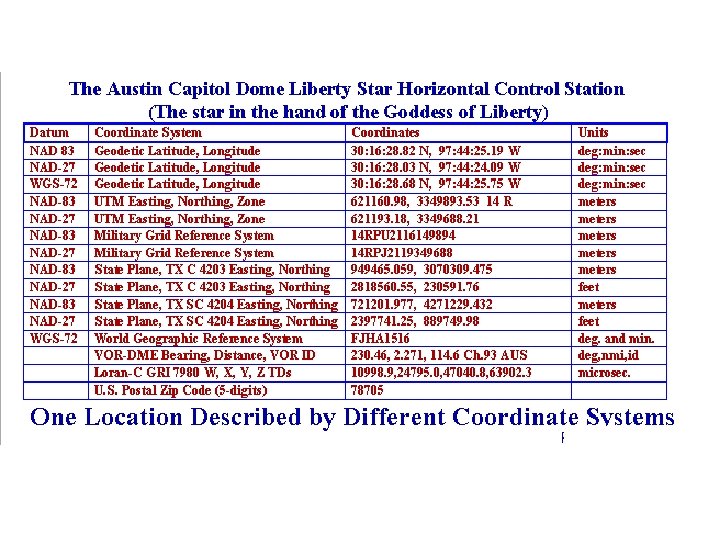
Reference Systems: SUMMARY 2/2 • Geodetic datum defines the size and shape of the earth and the origin and orientation of the coordinate systems used to map the earth. • Numerous different datums have been created and used so far, evolving from those describing a spherical earth to ellipsoidal models derived by modern techniques, such as satellite observations • Modern geodetic datums range from flat-earth models used for plane surveying to complex, global models, which completely describe the size, shape, orientation, gravity field, and angular velocity of the earth. • Potential problems: • Referencing geodetic coordinates to the wrong datum can result in significant position errors • The diversity of datums in use today and the technological advancements that have made possible global positioning measurements with sub-decimeter accuracies require careful datum selection and careful conversion between coordinates in different datums.
• Datums are created by geodesists, while cartography, surveying, navigation, and astronomy are the end users • National Imagery and Mapping Agency (NIMA), former Defense Mapping Agency created WGS 84 – World Geodetic Datum 84 • National Geodetic Survey (NGS) created NAD 83 – North American Datum 83 • International Earth Rotation Service (IERS) created ITRFxx, where xx stands for the reference year at which the frame was (re)established or (re)computed • ITRF stands for International Terrestrial Reference Frame • ITRF coordinates can be expressed in WGS 84 at 10 cm level • Newest ITRF refers to epoch 2000 (ITRF 2000)
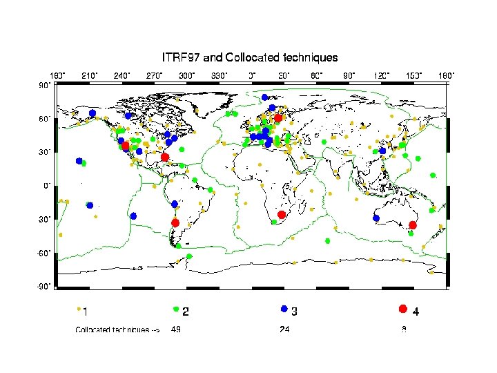
ITRF 200 Reference Frame
What is ITRF ? • The International Earth Rotation Service (IERS) has been established in 1988 jointly by the International Astronomical Union (IAU) and the International Union of Geodesy and Geophysics (IUGG). The IERS mission is to provide to the worldwide scientific and technical community reference values for Earth orientation parameters and reference realizations of internationally accepted celestial and terrestrial reference systems • In the geodetic terminology, a reference frame is a set of points with their coordinates (in the broad sense) which realize an ideal reference system • The frames produced by IERS as realizations of ITRS are named International Terrestrial Reference Frames (ITRF). • Such frames are all (or a part of) the tracking stations and the related monuments which constitute the IERS Network, together with coordinates and their time variations.
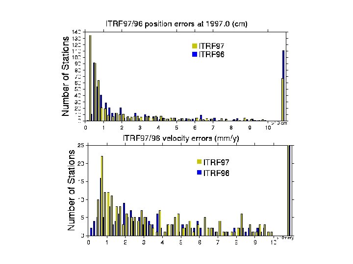
ITRF 97 • The reference frame definition (origin, scale, orientation and time evolution) is achieved in such a way that ITRF 97 is in the same system as the ITRF 96 • Station velocities are constrained to be the same for all points within each site; • ITRF 97 positions were estimated at epoch 1997. 0; • Transformation parameters (at epoch 1997. 0) and their rates from ITRF 97 to each individual solution were also estimated. • Transformation between ITRF at epoch 1997. 0 and other frames: • Ri represent rotations, D scale change and Ti stands for translation; i=1, 2, 3
TRANSFORMATION PARAMETERS AND THEIR RATES FROM ITRF 94 TO OTHER FRAMES -----------------------------------------------SOLUTION RATES T 1 T 2 T 3 D R 1 R 2 R 3 EPOCH Ref. cm cm cm . . . . T 1 T 2 T 3 D R 1 R 2 R 3 10 -8. 001" IERS Tech. Note #, page cm/y 10 -8/y. 001"/y -----------------------------------------------ITRF 93 0. 6 -0. 5 -1. 5 0. 04 -0. 39 0. 80 -0. 96 88. 0 RATES -0. 29 0. 04 0. 08 0. 00 -0. 11 -0. 19 0. 05 18 82 ITRF 92 0. 8 0. 2 -0. 8 -0. 08 0. 0 88. 0 18 80 ITRF 91 2. 0 1. 6 -1. 4 0. 06 0. 0 88. 0 15 44 ITRF 90 1. 8 1. 2 -3. 0 0. 09 0. 0 88. 0 12 32 ITRF 89 2. 3 3. 6 -6. 8 0. 43 0. 0 88. 0 9 29 ITRF 88 1. 8 0. 0 -9. 2 0. 74 0. 1 0. 0 88. 0 6 34
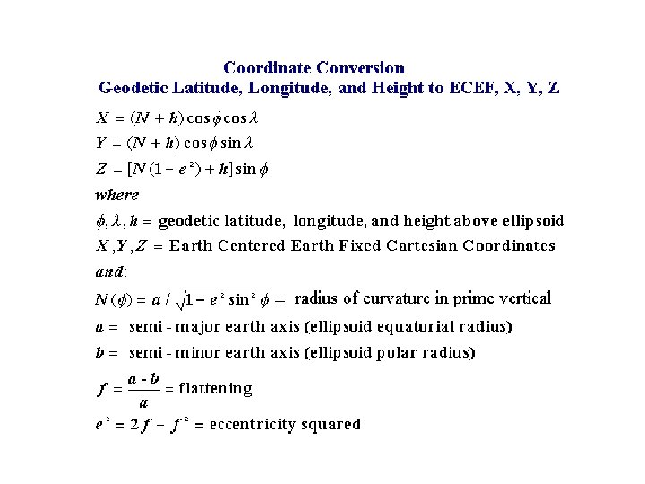
X, Y, Z (Lat, Lon, h) based on the definition of WGS 84 ellipsoid
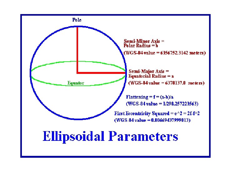
WGS 84 Four Defining Parameters Parameter Notation Magnitude Semi-major Axis a 6378137. 0 meters Reciprocal of Flattening 1/f 298. 257223563 Angular Velocity of the Earth w 7292115. 0 x 10 -11 rad sec -1 Earth’s Gravitational. Constant GM 3986004. 418 x 10 8 m 3 /s 2 (Mass of Earth’s Atmosphere Included) a and 1/f are the same as in the original definition of WGS 84
World Geodetic System 1984 (WGS 84) • The original WGS 84 reference frame established in 1987 was realized through a set of Navy Navigation Satellite System (NNSS) or TRANSIT (Doppler) station coordinates • Significant improvements in the realization of the WGS 84 reference frame have been achieved through the use of the NAVSTAR Global Positioning System (GPS). • Currently WGS 84 is realized by the coordinates assigned to the GPS tracking stations used in the calculation of precise GPS orbits at NIMA (former DMA). • NIMA currently utilizes the five globally dispersed Air Force operational GPS tracking stations augmented by seven tracking stations operated by NIMA. The coordinates of these tracking stations have been determined to an absolute accuracy of ± 5 cm (1 s).
World Geodetic System 1984 (WGS 84) Using GPS data from the Air Force and NIMA permanent GPS tracking stations along with data from a number of selected core stations from the International GPS Service for Geodynamics (IGS), NIMA estimated refined coordinates for the permanent Air Force and DMA stations. In this geodetic solution, a subset of selected IGS station coordinates was held fixed to their IERS Terrestrial Reference Frame (ITRF) coordinates.
World Geodetic System 1984 (WGS 84) Ø Within the past years, the coordinates for the NIMA GPS reference stations have been refined two times, once in 1994, and again in 1996. The two sets of self-consistent GPS-realized coordinates (Terrestrial Reference Frames) derived to date have been designated: • WGS 84 (G 730 or 1994) • WGS 84 (G 873 OR 1997) , where the ’G’ indicates these coordinates were obtained through GPS techniques and the number following the ’G’ indicates the GPS week number when these coordinates were implemented in the NIMA precise GPS ephemeris estimation process. Ø These reference frame enhancements are negligible (less than 30 centimeters) in the context of mapping, charting and enroute navigation. Therefore, users should consider the WGS 84 reference frame unchanged for applications involving mapping, charting and enroute navigation.
Differences between WGS 84 (G 873) Coordinates and WGS 84 (G 730), compared at 1994. 0 Station Location NIMA Station Number East (cm) North (cm) Ellipsoid Height (cm) Air Force Stations Colorado Springs 85128 0. 1 1. 3 3. 3 Ascension 85129 2. 0 4. 0 -1. 1 Diego Garcia(<2 Mar 97) 85130 -3. 3 -8. 5 5. 2 Kwajalein 85131 4. 7 0. 3 4. 1 Hawaii 85132 0. 6 2. 7 Australia 85402 -6. 2 -2. 7 7. 5 Argentina 85403 -1. 0 4. 1 6. 7 England 85404 8. 8 7. 1 1. 1 Bahrain 85405 -4. 3 -4. 8 -8. 1 Ecuador 85406 -2. 0 2. 5 10. 7 US Naval Observatory 85407 39. 1 7. 8 -3. 7 China 85409 31. 0 -8. 1 -1. 5 NIMA Stations *Coordinates are at the antenna electrical center.
World Geodetic System 1984 (WGS 84) • The WGS 84 (G 730) reference frame was shown to be in agreement, after the adjustment of a best fitting 7 -parameter transformation, with the ITRF 92 at a level approaching 10 cm. • While similar comparisons of WGS 84 (G 873) and ITRF 94 reveal systematic differences no larger than 2 cm (thus WGS 84 and ITRF 94 (epoch 1997. 0) practically coincide). • In summary, the refinements which have been made to WGS 84 have reduced the uncertainty in the coordinates of the reference frame, the uncertainty of the gravitational model and the uncertainty of the geoid undulations. They have not changed WGS 84. As a result, the refinements are most important to the users requiring increased accuracies over capabilities provided by the previous editions of WGS 84.
World Geodetic System 1984 (WGS 84) • The global geocentric reference frame and collection of models known as the World Geodetic System 1984 (WGS 84) has evolved significantly since its creation in the mid-1980 s primarily due to use of GPS. • The WGS 84 continues to provide a single, common, accessible 3 -dimensional coordinate system for geospatial data collected from a broad spectrum of sources. • Some of this geospatial data exhibits a high degree of ’metric’ fidelity and requires a global reference frame which is free of any significant distortions or biases. For this reason, a series of improvements to WGS 84 were developed in the past several years which served to refine the original version.
Other commonly used spatial reference systems • North American Datum 1983 (NAD 83) • State Plane Coordinate System (SPCS) based on NAD 83 • Universal Transverse Mercator (UTM)
North American Datum (NAD) NAD 27 established in 1927 Ø defined by ellipsoid that best fit the North American continent, fixed at Meades Ranch in Kansas Øover the years errors and distortions reaching several meters were revealed In 1970’s and 1980’s NGS carried out massive readjustment of the horizontal datum, and redefined the ellipsoid The results is NAD 83 (1986) Ø based on earth-centered ellipsoid that best fits the globe and is more compatible with GPS surveying Ø in 1990’s state-based networks readjustment and densification, accuracy improvement with GPS (HARN and CORS networks)
NAD 83 Defining Parameters Parameter Semi-major Axis Reciprocal of Flattening Notation Magnitude a 6378137. 0 meters 1/f 298. 2572221 Datum point – none Longitude origin – Greenwich meridian Azimuth orientation – from north Best fitting – worldwide X, Y, Z (Lat, Lon, h) based on the definition of GRS 80 ellipsoid
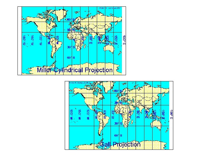
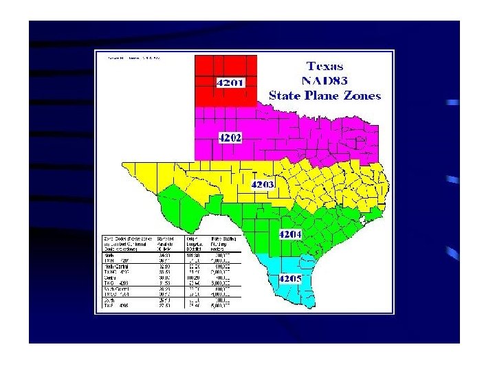
State Plane Coordinate System Ø Based on Lambert and Transverse Mercator projections Ø Developed in 1930’s and redefined in 1980’s and 90’s Ø NAD ellipsoid was projected to the conical (Lambert) and cylindrical (Transverse Mercator) flat surfaces ØAllowed the entire USA to be mapped on a set of flat surfaces with no more than one foot distortion in every 10, 000 feet (maximum scale distortion 1 in 10, 000) Ø Coordinates used are called easting and northing; derived from NAD latitude, longitude and ellipsoidal parameters
Lambert projection
Lambert projection
Transverse Mercator Projection
State Plane Coordinate System Ø The scale of the Lambert projection varies from north to south, thus, it is used in areas mostly extended in the east-west direction Ø Conversely, the Transverse Mercator projection varies in scale in the east-west direction, making it most suitable for areas extending north and south Ø Both projections retain the shape of the mapped surface Ø Each state is usually covered by more than one zone, which have their own origins – thus, passing the zone boundary would cause the coordinate jump!
Universal Transverse Mercator, UTM Ø Developed by the Department of Defense for military purpose Ø It is a global coordinate system Ø Has 60 north-south zones numbered from west to east beginning at the 180 th meridian Ø The coordinate origin for each zone is at its central meridian and the equator
Universal Transverse Mercator • UTM zone numbers designate 6 -degree longitudinal strips extending from 80 degrees south latitude to 84 degrees north latitude • UTM zone characters designate 8 -degree zones extending north and south from the equator • There are special UTM zones between 0 degrees and 36 degrees longitude above 72 degrees latitude, and a special zone 32 between 56 degrees and 64 degrees north latitude
UTM Zones • Each zone has a central meridia. Zone 14, for example, has a central meridial of 99 degrees west longitude. The zone extends from 96 to 102 degrees west longitude • Easting are measured from the central meridian, with a 500 km false easting to insure positive coordinates • Northing are measured from the equator, with a 10, 000 km false northing for positions south of the equator
Ohio State Plane (Lambert projection, two zones) and UTM Coordinate Zone
Universal Transverse Mercator, UTM
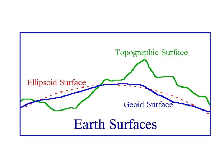
Vertical Datum Definition 1/2 Ø Horizontal control networks provide positional information (latitude and longitude) with reference to a mathematical surface called sphere or spheroid (ellipsoid) Ø By contrast, vertical control networks provide elevation with reference to a surface of constant gravitational potential, called geoid (approximately mean see level) • this type of elevation information is called orthometric height (height above the geoid or mean sea level) level determined by spirit leveling (including gravity measurements and reduction formulas). Ø Height information referenced to the ellipsoidal surface is called ellipsoidal height This kind of height information is provided by GPS
Height Systems Used in the USA Ø Orthometric Ø Normal (orthometric normal) Ø Dynamic Ø Ellipsoidal Variety of height systems (datums) used requires careful definition of differences and transformation among the systems
Vertical Datum Definition 2/2 Ø Vertical datum is defined by the surface of reference – geoid or ellipsoid Ø An access to the vertical datum is provided by a vertical control network (similar to the network of reference points furnishing the access to the horizontal datums) Ø Vertical control network is defined as an interconnected system of bench marks Ø Why do we need vertical control network? • to reduce amount of leveling required for surveying job • to provide backup for destroyed bench marks • to assist in monitoring local changes • to provide a common framework
ØThe height reference that is mostly used in surveying job is orthometric Ø Orthometric height is also commonly provided on topographic maps ØThus, even though ellipsoidal heights are much simpler to determine (eg. GPS) we still need to determine orthometric heights
Q - angle between the normal to the ellipsoid and the vertical direction (normal to the geoid), so-called deflection of the vertical H – orthometric height h – ellipsoidal height h=H+N N – geoid undulation (computed from geoid model provided by NGS) Normal to the ellipsoid P H h N Normal to the geoid (plumb line or vertical) terrain geoid ellipsoid
Orthometric vs Ellipsoidal Height (Orthometric height) (computed from a geoid model)
So, how do we determine orthometric height? Ø By spirit leveling Ø And gravity observations along the leveling path, or Ø Recently -- GPS combined with geoid models (easy!!!) but not as accurate as spirit leveling + gravity observations H = h-N But why do we need gravity observations with spirit leveling? Because the sum of the measured height differences along the leveling path between points A and B is not equal to the difference in orthometric height between points A and B Why?
Level Surfaces and Plumb Lines 1/2 Equipotential surfaces are not parallel to each other
Level Surfaces and Plumb Lines 2/2 Ø The level surfaces are, so to speak, horizontal everywhere, everywhere they share the geodetic importance of the plumb line, because they are normal to it ØPlumb lines (line of forces, vertical lines) are curved Ø Orthometric heights are measured along the curved plumb lines ØEquipotential surfaces are rather complicated mathematically and they are not parallel to each other Ø Consequently: Ø Orthometric heights are not constant on the equipotential surface ! Ø Thus, points on the same level surface would have different orthometric height !
Spirit leveling Height differences between the consecutive locations of backward and forward rods correspond to the local separation between the level surfaces through the bottom of the rods, measured along the plumb line direction
Orthometric Height vs. Spirit Leveling C 4 dh 3 C 2 dh 1 C 1 dhi H C 1, C 2, C 3, C 4 – geopotential numbers corresponding to level (equipotential) surfaces dh 1, dh 2, dh 3, dh 4 – height difference between the level surfaces (determined by spirit leveling, path-dependent); their sum is not equal to H ! Because equipotential surfaces are not parallel to each other
Geopotential Numbers 1/3 Ø The difference in height, height dh, measured during each set up of leveling can be converted to a difference in potential by multiplying dh by the mean value of gravity, gm, for the set up (along dh). geopotential difference = gm*dh Ø Geopotential number C, C or potential difference between the geoid level W 0 and the geopotential surface WP through point P on the Earth surface (see Figure 2 -8), is defined as Where g is the gravity value along the leveling path. This formula is used to compute C when g is measured, and is independent on the path of integration!
Geopotential Numbers 2/3 Since the computation of C is not path-dependent, path-dependent the geopotential number can be also expressed as C = gm*H, where H is the height above the geoid (mean sea level) and gm represents the mean value of gravity along H (along the plumb line at point P on Figure 2 -8; see “orthometric height vs. spirit leveling) Ø the last relationship justifies the units for C being kgal*meter; it is not used to determine C! Ø Finally: Ø Geopotential number is constant for the geopotential (level) surface Ø Consequently, geopotential numbers can be used to define height and are considered a natural measure for height REMEMBER: Orthometric heights are not constant on the equipotential surface !
Ø Observed difference in height depends on leveling route Ø Points on the same level surface have different orthometric heights Local normal (plumb line direction) to equipotential (level) surfaces dhup P 1 dhdown P 2 S 3 H 1 Reference surface (geoid) H 2 S 1 Orthometric height measured along the plumb line direction H = H 1 -H 2 dhup + dhdown 0 No direct geometrical relation between the results of leveling and orthometric heights
What then, if not orthometric height, is directly obtained by leveling? Ø If gravity is also measured, then geopotential numbers, C (defined by the integral formula shown earlier), result from leveling Ø Thus, leveling combined with gravity measurements furnishes potential difference, that is, physical quantities Ø Consequently, orthometric height are considered as quantities derived from potential differences Ø Thus, leveling without gravity measurements introduces error (for short lines might be neglected) to orthometric height
Geopotential Numbers 3/3 Let’s summarize: ØThe sum of leveled height differences between two pints, A and B, on the Earth surface will not equal to the difference in the orthometric heights HA and HB ØThe difference in height, dh, measured during each set up of leveling depends on the route taken, as level (equipotential) surfaces are not parallel to each other Ø Consequently, based on the leveling and gravity measurements Ø the geopotential numbers are initially estimated (using the integral formula introduced earlier), based on the leveling and gravity measurements along the leveling path Ø geopotential numbers can then be converted to heights (orthometric, normal or dynamic – see definitions below) if gravity value along the plumb line through surface point P is known Height = C/gravity
Height Systems 1/5 Ø In order to convert the results of leveling to orthometric heights we need gravity inside the earth (along the plumb line) Ø since we cannot measure it directly, as the reference surface lies within the Earth, beneath the point, we use special formulas to compute the mean value of gravity, along the plumb line, based on the surface gravity measured at point P Øreduction formulas used to compute the mean gravity, gm, based on gravity measured at point P on the Earth surface lead to: Ø Orthometric height, (H = C/gm) or Ø The reduction formula used to compute mean gravity, based on normal gravity at point P on the Earth surface leads to: to Ø Normal (also called normal orthometric) height, (H* = C/ m ) Where is so-called normal gravity (model) corresponding to the gravity field of an ellipsoid of reference (Earth best fitting ellipsoid), and subscript “m” stands for “mean”
Height Systems 2/5 Ø We can also define dynamic heights Ø use normal gravity, 45, defined on the ellipsoid at 45 degree latitude, (HD = C/ 45) ØNote: term “normal gravity” always refers to the gravity defined for the reference ellipsoid, while “gravity” relates to geoid or Earth itself
Height Systems 3/5 Sometimes, instead of formulas provided above (involving C), it is convenient to use correction terms and apply them to the sum of leveled height differences: Ø Consequently, the measured elevation difference has to be corrected using so-called orthometric correction to obtain orthometric height (height above the geoid) Max orthometric correction is about 15 cm per 1 km of measured height difference Ø Or, the measured elevation difference has to be corrected using so -called dynamic correction to obtain dynamic height (no geometric meaning and factual reference surface; defined mathematically) Ø Or, normal correction is used to derive normal heights Ø All corrections need gravity information along the leveling path (equivalent to computation of C based on gravity observations!)
Height Systems 4/5 Ø Dynamic heights are constant for the level surface, and have no geometric meaning Ø Orthometric height Ødiffers for points on the same level surface because the level surfaces are not parallel. This gives rise to the well-known paradoxes of “water flowing uphill” Ø measured along the curved plumb line with respect to geoid level Ø Normal height of point P on earth surface is a geometric height above the reference ellipsoid of the point Q on the plumb line of P such as normal gravity potential and Q is the same as actual gravity potential at P. Ø measured along the normal plumb line (“normal” refers to the line of force direction in the gravity field of the reference ellipsoid (model)) Ø All above types of heights are derived from geopotential numbers
Height Systems 5/5 ØA disadvantage of orthometric and normal heights is that neither indicates the direction of flow of water. Only dynamic heights possess this property. ØThat is, two points with identical dynamic heights are on the same equipotential surface of the actual gravity field, and water will not flow from one to the other point. ØTwo points with identical orthometric heights lie on different equipotential surfaces and water will flow from one point to the other, even though they have the same orthometric height ØThe last statement holds for normal heights, although due to the smoothness of the normal gravity field, the effect is not as severe
Vertical Datums: NGVD 29 and NAVD 88 Ø NGVD 29 – National Geodetic Vertical Datum of 1929 • defined by heights of 26 tidal stations in US and Canada • uses normal orthometric height (based on normal gravity formula) Ø NAVD 88 – North American Vertical Datum of 1988 • defined by one height (Father Point/Rimouski, Quebec, Canada) • 585, 000 permanent bench marks • uses Helmert orthometric height (based on Helmert gravity formula) • removed systematic errors and blunders present in the earlier datum • orthometric height compatible with GPS-derived height using geoid model • improved set of heights on single vertical datum for North America
Vertical Datums: NGVD 29 and NAVD 88 Ø Difference between NGVD 29 and NAVD 88 • ranges between – 40 cm to 150 cm • in Alaska between 94 and 240 cm • in most stable areas the difference stays around 1 cm • accuracy of datum conversion is 1 -2 cm, may exceed 2. 5 cm • transformation procedures and software provided by NGS (www. ngs. noaa. gov)
International Great Lake Datum (IGLD) 1985 Ø IGLD 85 • replaced earlier IGLD 1955 • defined by one height (Father Point/Rimouski, Quebec, Canada) • uses dynamic height (based on normal gravity at 45 degrees latitude) • virtually identical to NAVD 88 but published in dynamic heights!
Vertical Datums Ø Use of proper vertical datum (reference surface) is very important Ø Never mix vertical datums as ellipsoid – geoid separation can reach 100 m! Ø Geoid undulation, N, is provided by models (high accuracy, few centimeters in the most recent model) developed by the National Geodetic Survey (NGS) and published on their web page www. ngs. noaa. gov So, in order to derive the height above the see level (H) with GPS observations – determine the ellipsoidal height (h) with GPS and apply the geoid undulation (N) according to the formula H = h - N