GRETA Electronics and requirements Chris Campbell Thanks to
 and GRETINA")
GRETA Electronics and requirements Chris Campbell Thanks to Thorsten Stezelberger (LBNL engineer) and GRETINA Electronics working group + Mike Carpenter

Outline • GRETA Working Group Workshop - Focus on Electronics, Auxiliary Detectors and Facility Interfaces - Nov 30 – Dec. 1, 2017 • Discussion of problems – ADC issues • Physics inputs/requirements to GRETA Electronics (Engineers) • Spectrum requirements • Trigger requirements • GRETA Electronics Systems • Initial design considerations – ADC quality and cooling
 • Linearity effects • Shifts peak positions relative")
GRETINA lessons: ADC linearity (and fidelity) • Linearity effects • Shifts peak positions relative to linear • Can produce peak shoulder or doublet • At higher rates, peaks shift with baseline (typically asymmetric sawtooth residuals) (for some, not all peaks) (becomes complicated) • Broadens peaks, can cause doublets or tails to high or low energy • ADC STEP scale problem >>> Smaller spectrum effects from smaller kev/ch • Fidelity • Issues beyond static ADC channel width variation • Observed time-structure to some problems • Energy resolution at rate depends on Pole-Zero math accurately describing the waveform • Signal = sum of exponentials • Must TEST ADC thoroughly! • signal=expectation, exhaustive pulser tests, and real preamp signals at varying rates

GRETA needs • Select best ADC for GRETA use case • Requires testing (my problem) • Knowledge of REQUIREMENTS (community input) • In the absence of a perfect, economical, low-power ADC, • Choices, tradeoffs, mitigation of problems, maximize physics reach • All ADCs will have some nonlinearity • The effect on the spectrum will scale with gain/range, i. e. ke. V/ch or total Me. V • Spectrum nonlinearity ~ (ADC step nonlinearity) * (energy range) • The #1 question I have for testing ADC & building Digitizers: • What energy range(s) are actually needed and why?

How to chose ADC range and preamp reset ? • Biggest gamma-ray to observe <= your physics • Energy deposition distribution and rate <= your physics + background • Need gamma spectrum emitted or energy spectrum measured • Need rates • Energy deposited + Rates + Statistical simulation >>> predicted baseline distribution • Protons (light charged particles) • Observed at S 800 • Bigger issue at HRS – forward angles populated • 10’s Me. V deposited in core and one-few segments • Which mitigation strategies will work for various cases • Do all energies need “best” obtainable resolution? • If someone studies a 12 Me. V gamma, do they care if the resolution degraded? • How much degradation is acceptable?

Related: ADC Overflow • Overflow depends on both past gamma tails and current gamma amplitude • Sources • Many gammas (e. g. 1 Me. V) stack-up in a short time period (tpreamp = 50 ms) • One high energy gamma, >10 Me. V • One high energy particle • Mitigation Strategies • • Wait => dead time Overflow time + Filter restart/recovery Segment sums Time-over-threshold Resistive preamp + pulsed reset

ADC Non-Linearity Mitigation Strategies • Channel-scale issue => maximize channels per ke. V, Minimize Range • Tailor to signal polarity • Gretina has +/- 10 Me. V segment ADCs • One might change that to -2 Me. V to 10 Me. V, reducing non-linearity by 40% in energy • Have multiple ADC ranges for same signal • Buffer Amp copies signal faithfully • Telescoping Ranges as in Gretina: 2. 5, 5, 10, 30 Me. V • Stacking Ranges • Shifted ranges with small overlap • Each ADC covers same energy delta • E. g. 0 -10, 9 -19, 18 -28 Me. V

ADC Non-Linearity Mitigation Strategies • Calibration of ADC step heights • • Depends on static vs. dynamic effects Depends on stability of non-linearity as a function of conditions and reset Perhaps correct some subset of similar, large-problem channels Must be done at 100 MHz, or in parallel to energy filter, on FPGA • Imposed signal • Think Dither or Gatti slider • Adding a known, varying signal in analog and subtracting it in digital • Depends on distribution of non-linearities and added signal quality • Offset signal • Conditionally subtract an offset in analog to allow expanded effective range for ADC

Physics requirements

High resolution spectrum requirements • Required Range: 0 -10 Me. V • Resolution at 1 k. Hz incident rate • @ 0. 060 Me. V • @ 1. 33 Me. V <= 1. 8 ke. V <= 2. 5 ke. V • Resolution at 50 k. Hz incident rate • @ 1. 33 Me. V <= 3. 5 ke. V • Rate performance • Core >= 50 k. Hz / crystal • Segments >= 10 k. Hz / segment

Fast beam spectrum requirements • Required Range: 0 -15 Me. V (for Doppler shift, Erest<10 Me. V) • Resolution requirement relaxed by (0. 5% * Egamma) added in quadrature • Additional Preamp issue: charged particles (10’s-100’s Me. V) • Core and front segments • Additional channel to cover Full core preamp output range • System Calibration / linearity verification must be tractable!

Excess ADC ranges needed • Core: • 50 k. Hz/crystal with an <E>=0. 75 Me. V • Result in preamp baseline shifts of +/-5 Me. V • Segments: • Observe opposite-polarity induced signals • Estimate : -2 Me. V

Trigger Requirements – Fast trigger • Generate a fast trigger based on crystal multiplicity within 500 ns of gammarays interacting with the detector with a 100 ke. V threshold placed on each crystal. (This latency is acceptable for all currently known applications and auxiliary detectors. ) • The walk associated with the discriminator employed on individual channels used to construct the fast trigger should be < 600 ns to allow for all prompt gamma-rays to contribute to the fast multiplicity calculations assuming a threshold set at 100 ke. V for individual channels. • Additional fast trigger requirements have been requested for fast beam experiments: • 2 level trigger – read out all crystals above threshold X if a multiplicity requirement is met with threshold set to Y. • Upper level discriminator for multiplicity determination (veto charged particles) • Multiple crystal multiplicity triggers based on patterns e. g. front multiplicity >= X and/or back multiplicity >= Y

Trigger Requirements – Slow triggers, counters • Slower Triggers will be constructed which can be overlapped with each other and/or with external triggers from other detector systems. These triggers will include: CFD multiplicity (eliminate walk and provide tighter coincidence window) Total Energy sum of central contacts Hit pattern multiplicity Delayed multiplicity Additional algorithms may be required such as those suggested for fast triggers. • Not all trigger algorithms need to be available simultaneously. • • • Trigger information should be recorded with each GRETA channel including , (i) the trigger condition satisfied for the triggered channel and (ii) timestamp when triggers(s) was satisfied • Trigger counters indicating both raw and accepted trigger rates will be provided.

Trigger Requirements – General • The trigger system will be able to generate at least 480, 000 triggers/sec. • The trigger and timing systems will be able to accommodate up to four ancillary DAQ systems providing both trigger capabilities and clock synchronization. • A buffer of at least 20 msec will be available in the digitizer to provide overlap triggering between GRETA and other delayed triggers e. g from RMS, FMA).

Trigger Requirements – External DAQs • External triggers from ancillary devices can both trigger GRETA and be overlapped with other external triggers as well as the GRETA internal triggers. • Back-compatibility to GRETINA/My. RIAD systems, which are used by numerous auxiliary devices. • Timing outputs needed: 100 MHz GRETA clock; downsampled GRETA clock, NIM signal for timestamp reset signal • Record within GRETA external clocks up to 1 GHz from outside systems (number) as well as the ability to synchronize the clock at their fundamental frequencies. • Provide nanosecond timing relative to an external clock or detector (i. e. accelerator RF)

Other Requirements • An equivalent to ‘Bank 29’ is requested with 10++ channels of digitizers synced within the GRETA system to natively incorporate external signals • GRETA digitizers, possibly in a different form factor, which could be used by other detection systems.

Click to edit Master title style GRETA Electronics Systems: Digitizer and Signal Filter Board Thorsten Stezelberger Level 3 Manager – GRETA Electronics Systems – LBNL Scope Engineering Division Lawrence Berkeley National Laboratory Gamma Ray Energy Tracking Array U. S. Department of Energy Office of Science Lawrence Berkeley National Laboratory Thorsten Stezelberger 18 DOE/SC CD-1 Review of the GRETA Project April 25 -27, 2017 18

The Digitization GRETA Thorsten Stezelberger 19
 • Pulse")
The ADC test setup • Signal Generation • Source + Detector (shown) • Pulse Generator • Data Collection • ADC Board • FPGA Board • ADC Data streamed over 10 Gb. E to Computer • Data Analysis • Offline using MATLAB GRETA Thorsten Stezelberger 20

Preliminary DNL Test Results AD 9655 • DNL pattern is not reproducible LTC 2194 • DNL pattern is reproducible AD 9655 Both shown modern ADCs have improved DNL over the GRETINA ADC 30000 25000 20000 15000 10000 LTC 2194 GRETA 1 2000 3999 Current GRETINA ADC AD 6645 Thorsten Stezelberger 21

The Digitizer Module Cooling And Temperature Control The Digitizer Module will be compact • Cooling and Thermal Stability will be important • Analog Components have a Temperature Coefficient • Temperature Coefficient changes the performance (mainly Gain) Temperature Characteristics of a Analog Devices ADR 1581 Voltage Reference (This Device was selected at random as example) Initial static and transient thermal simulations have been performed GRETA Thorsten Stezelberger 22

END GRETA Thorsten Stezelberger 23
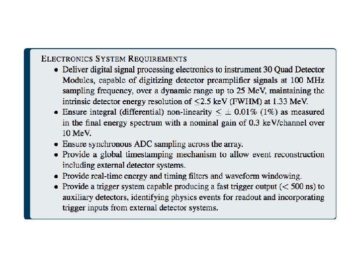

CDR numbers meaning for spectroscopy • Dynamic range “up to 25 Me. V” • Preamplifier voltage output range in which signals could be measured • Final energy spectrum: 0. 3 ke. V/channel, 0 -10 Me. V • Integral non-linearity [INL](<= 0. 01%) >>> 10000 ke. V*0. 01% = 1 ke. V • Up to +/-1 ke. V deviation anywhere in 0 -10 Me. V spectrum • Differential non-linearity [DNL](<= 1%) *1%=0. 003 ke. V/ch >>> 0. 3 ke. V/ch >>> counts vary <= 1% systematic • Relation INL<->DNL >>> 1 ke. V/(0. 003 ke. V/ch) = 333 ch • Channel width may vary up to 1% • 1 ke. V max calibration deviation (INL) must occur slowly due to DNL • 1 ke. V variation takes at least 333 channels >>> 333 ch * 0. 3 ke. V/ch = 100 ke. V • INL and DNL set limits, not average behavior. Multiple deviations could occur in spectrum with or without a pattern • Effective requirement, <=2. 5 ke. V FWHM @1. 33 Me. V (at rate) • Also constrains INL condition

Click to edit Master title style GRETA Electronics Systems: Digitizer and Signal Filter Board Thorsten Stezelberger Level 3 Manager – GRETA Electronics Systems – LBNL Scope Engineering Division Lawrence Berkeley National Laboratory Gamma Ray Energy Tracking Array U. S. Department of Energy Office of Science Lawrence Berkeley National Laboratory Thorsten Stezelberger 26 DOE/SC CD-1 Review of the GRETA Project April 25 -27, 2017 26

The Motivations driving the Architecture • Provide Digitization of the Detector signals as close as possible to the Detector (36 Segment + 1 Central Contact) • Allow for Digitizer change without removing services to the crystal • Data Transfer to Computing System • At least 4000 Validated Events/Crystal/s • 32 MByte/Crystal/s • Upgradeable Digital Signal Processing • Utilize new components and technologies • Simplify Cabling GRETA Thorsten Stezelberger 27

The GRETA Electronics Block Diagram • The Following Slides will follow the Data Flow from the Detector to the Computing System • The Description is for one Crystal. GRETA will have 120 Crystals GRETA Thorsten Stezelberger 28

The Detector Interface GRETA Thorsten Stezelberger 29

The Detector Interface Box • Power crystal without Digitizer Module • Useful during acceptance tests • Swap Digitizer Module without Biasing Down The Crystal • Can stay on the Detector Interface Box Digitizer Module Detector Power Cable GRETA Thorsten Stezelberger 30

The Functions of the Interface Box • • • Bring Power to the Crystal/Detector Interface to Temperature Interlock Interface to Temperature sensors in the Quad Detector Pass the Crystal Signals to the ADC Module Pass test signals from ADC Module to detector test segments • Provide interface to probe detector signal using a scope GRETA Thorsten Stezelberger 31

Potential Detector Interface Box to Digitizer Module connector • Connector Properties • PCB Mount • Rugged / Durability • High Density / Differential Pins • Low Crosstalk • Low Cost • Candidate for the Connector • Samtec HDAF HDAM series We have a candidate and will research and select a connector at design time GRETA Thorsten Stezelberger 32

The Digitizer GRETA Thorsten Stezelberger 33

The Digitizer Module • 36+1 Crystal Signals to Digitize • Simple / Small FPGA • Timestamp and Send Waveform data • Simple Filters to generate Trigger data GRETA Thorsten Stezelberger 34

The Digitizer Module Functions • Analog Frontend for 36+1 Crystal Segment Signals • • • Termination and Buffering Anti Aliasing Filter ADC driver • Digitize 36+1 Crystal Signals • • Digitize Synchronous >= 100 MS/s (from GRETINA) >= 14 bit (from GRETINA) Timestamp ADC Data Operate synchronous to global clock Package ADC data and transmit to Signal Filter Board Generate Trigger Data • • • GRETA Intended for trigger system to make trigger decisions Fast Trigger Data is simple with short latency for external detectors Slow Trigger Data can include more. e. g. : • Initial energy estimate • Map of segments over threshold • First Segment over threshold Thorsten Stezelberger 35

The Digitizer Module’s Location Digitizer Modules will be located at current “Radiall Box” location “Radiall Box” GRETINA Detector with “Radiall Box” GRETA Thorsten Stezelberger 36

The Digitization GRETA Thorsten Stezelberger 37
 • • >=")
The ADC for GRETA Requirements for Candidates (Based on GRETINA experience) • • >= 14 bit (Up to 25 Me. V) >= 100 MSamples/s Low power Package Size LTC 2194 Evaluation Board • We identified 3 Candidates (16 bit / 100 MSamples/s) • • • AD 9655 AD 9653 LTC 2194 • We compared the ADCs • One of the ADCs looks promising (LTC 2194) We will monitor the market for new ADCs and make the final decision at design time GRETA Thorsten Stezelberger 38

The Envisioned ADC Characterization Tests Datasheets do not provide all the Information we need Tests • Differential Non-Linearity (DNL) • Integral Non-Linearity (INL) • Crosstalk • Noise • Temperature stability • Memory effects • Physics related data analysis • Overshoot • Radioactive Source GRETA Thorsten Stezelberger 39
 • Pulse")
The ADC test setup • Signal Generation • Source + Detector (shown) • Pulse Generator • Data Collection • ADC Board • FPGA Board • ADC Data streamed over 10 Gb. E to Computer • Data Analysis • Offline using MATLAB GRETA Thorsten Stezelberger 40

Preliminary DNL Test Results AD 9655 • DNL pattern is not reproducible LTC 2194 • DNL pattern is reproducible AD 9655 Both shown modern ADCs have improved DNL over the GRETINA ADC 30000 25000 20000 15000 10000 LTC 2194 GRETA 1 2000 3999 Current GRETINA ADC AD 6645 Thorsten Stezelberger 41

Preliminary LTC 2194 Performance Results Co 60 HPD : Single Pole Correction: 2. 75 Ke. V DPC : Double Pole Correction: 2. 65 Ke. V GRETA Thorsten Stezelberger 42

The Digitizer Module Cooling And Temperature Control The Digitizer Module will be compact • Cooling and Thermal Stability will be important • • Analog Components have a Temperature Coefficient changes the performance (mainly Gain) Mitigations • For Best Detector Readout Performance we want to keep the Analog Electronics Temperature Stable • Where Possible select Components with small Temperature Coefficient Temperature Characteristics of a Analog Devices ADR 1581 Voltage Reference (This Device was selected at random as example) A. Hodgkinson (C 3 -3) GRETA Thorsten Stezelberger 43

The ADC Data Transfer GRETA Thorsten Stezelberger 44

The Fiber Link from the Digitizer Module to the Signal Filter Board • Stream ADC data from Digitizer Module to Filter Board • • ~64 Gbit/s between Boards Standard Networking Hardware is readily available • 100 Gbit/s • We used Data Streaming before • • GRETINA Test for real-time filtering on CPUs GRETA ADC Characterization • The use of Fiber makes grounding easier • The use of Fiber is easier to route GRETA Thorsten Stezelberger 45

The Digital Signal Processing GRETA Thorsten Stezelberger 46

The GRETA Signal Filter Board • Digital Only Board • Commercial FPGA Boards Possible • Compute Filters for all ADC data steams • Event Time • Event Energy • Package “Validated” Events and transmit to Computing System GRETA Thorsten Stezelberger 47
")
Signal Filter Board Functions • Digital Only Board • Commercial Of The Shelf (COTS) options are possible • Receive streamed ADC Waveform Data from Digitizer Module • Digital Signal Processing based on existing GRETINA Firmware code • • • Find signals using LED Compute Energy Code will be ported to take advantage of new FPGA Architectures • Real-time processing • The Signal Filter Board can run asynchronous as long as it keeps up with Digitizer Module • Assemble signals selected by the Trigger System and transmit them to Computing • • • GRETA Waveform Timestamp Energy Thorsten Stezelberger 48

A Commercial Of The Shelf Signal Filter Board • Leverage Commercial Products • Various Manufacturers offer powerful FPGA Board with Fiber Interfaces • Interfaces • Digitizer Module • Computing System • Trigger System • Slow Controls Fiber Optics Interface Modules Available FPGA Board We will research commercial FPGA Boards during the design phase GRETA Thorsten Stezelberger 49

The GRETA Filter Algorithms • The GRETA Filter Algorithms are built on GRETINA Signal Processing • LED Leading Edge Discriminator • Trapezoidal Filter • Pole-Zero Cancelation • Baseline Restoration • Energy Determination We intend to take advantage of the capabilities in modern FPGAs in the implementation of the Filter Algorithms GRETA Thorsten Stezelberger 50

Data Transfer to Computing • Use Standard Interfaces • 10 Gigabit Ethernet • 10 GBASE-SR • UDP protocol • Work with Computing on Data Format • Signal Filter Board will Push Data to the Computing Nodes • Capable to handle the required • ~32 MByte/Crystal/s • Flow Control Schemes exist • Details will be worked out at design time ADC Characterization Setup with 10 Gb. E GRETA Thorsten Stezelberger 51
- Slides: 51