Greenhouse gases reduction waste pyrolysis Lab Chapter 12

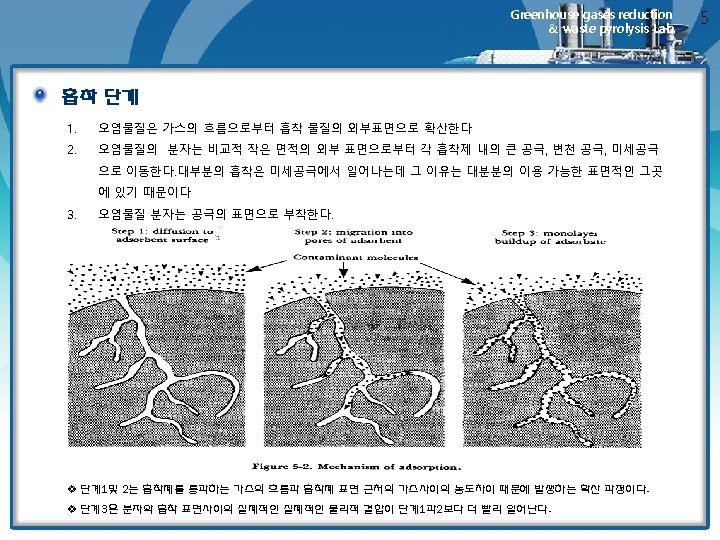
Greenhouse gases reduction & waste pyrolysis Lab. Chapter 12. Gas Adsorption Professor : Kwang Joong Oh kjoh@pusan. ac. kr Tel : 051 -510 -2417

Greenhouse gases reduction & waste pyrolysis Lab. Contents 12. 1 Introduction 12. 2 Adsorption Theory 12. 3 Physical properties of Adsorbents 12. 4 Fixed-Bed Adsorption Systems 12. 5 12. 6 12. 7 Design of Fixed-Bed Carbon Adsorption Systems Economics of Fixed-Bed Adsorption Systems Fluidized-Bed Adsorbers

12. 1 Introduction Greenhouse gases reduction & waste pyrolysis Lab. Adsorption • The removal of low-concentration gases and vapors from an exhaust stream by the adherence of these materials to the surface of porous solids is an example of a practical application of adsorption. • With the proper selection of the adsorbing solid and the contact time between the solid and the vapor-laden exhaust stream, very high removal efficiencies are possible. • Gas adsorption is used for industrial applications such as odor control ; the recovery of volatile solvents such as benzene, ethanol, trichloroethylene, freon and so forth ; and the drying of process gas streams 3

Greenhouse gases reduction & waste pyrolysis Lab. • we will first describe the components and the operation of a typical fixed- bed carbon system as shown in Figure 12. 1 • The system in Figure 12. 1 uses two horizontal cylindrical vessels in which a bed of granular activated carbon is supported on a heavy screen. • The air-vapor mixture from a plant process enters the main blower and is passed through a cooler. • The cooled gas stream then passes upward through the adsorbent bed, where the vapor is removed and the remaining air is either vented of returned to the source process. • The saturated bed is then regenerated by direct contact with low-pressure stream, which is admitted at the top if the bed. Figure 12. 1 simplified flow sheet for a fixed-bed carbon solvent recovery system. 4

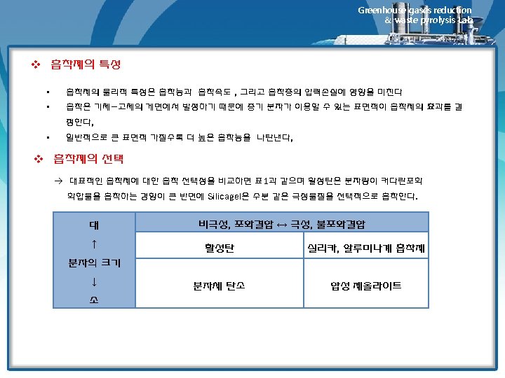
12. 2 Adsorption Theory Greenhouse gases reduction & waste pyrolysis Lab. Physical and Chemical Adsorption v Physical Adsorption • Physical adsorption referred to as van der Waals adsorption, involves a weak bonding of gas molecules to the solid. • The band energy is similar to the attraction forces between molecules in a liquid. • The adsorption process is exothermic, and the heat of adsorption is usually slightly higher than the heat of vaporization of the • The forces holding the gas molecules to the solid are easily overcome by either the application of heat or the reduction of pressure ; either of these methods can be used to regenerate the adsorbent. 흡착을 일으키는 물리적인 힘 6

Greenhouse gases reduction & waste pyrolysis Lab. v Chemisorption • Chemisorption involve an actual chemical bonding by the reaction of the adsorbate with the adsorbing solid. • Heat of chemisorption are of roughly the same magnitude as heats of reaction, and chemisorption is not easily reversible. • The oxidation of SO 2 to SO 3 on activated carbon is an example of chemisorption. • Activated carbon alumina can act as reaction catalysts with a number of gaseous mixtures • Except in some very specialized applications, if an adsorbate is chemically adsorbed to a significant extent, recovery of this material by an adsorption process is not feasible. < 물리적 흡착과 화학적 흡착의 특징 > 구분 물리흡착 화학흡착 온도 저온에서 흡착량이 크다 비교적 고온에서 일어난다 피흡착질 비선택성 적다(10 Kcal/mol 이하), 비교적 크다(10 Kcal/mol 이하), 응축열과 같은 정도 반응열과 같은 정도 흡. 탈착 가능(가역성) 불가능(비가역) 흡착속도 빠르다 느리다(활성화 에너지 필요) 흡착열 7

Greenhouse gases reduction & waste pyrolysis Lab. Adsorption isotherms • Generally, the capacity of an adsorbent to adsorb a particular adsorbate is directly proportional to the molecular weight and inversely proportional to the vapor pressure of the asdorbate • The capacity of an adsorbent for a specific gas or vapor can be presented as an isotherm, as shown in Figure 12. 2. • A point on an isotherm represents the mass of adsorbate per unit mass of adsorbent under equilibrium conditions at the indicated temperature and gas-phase concentration. • The isotherms shown in Figure 12. 2 are typical for many organic solvents in activated carbon. Figure 12. 2 Adsorption isotherms for activated carbon 8

Greenhouse gases reduction & waste pyrolysis Lab. • ra = rate of adsorption Ca = constant the rate of loss of molecules from the surface is proportional to the fraction of the surface occupied. ra = rate of loss by adsorption Ca = constant

Greenhouse gases reduction & waste pyrolysis Lab. • Since we assume a unimolecular coverage, the mass of adsorbate per unit mass of adsorbent a is also proportional to the fraction of surface covered. C’a = constant • Combining Eqs. (12. 4) and (12. 5), we obtain • since Ca, Cd and C’a are constants, Eq. (12. 6) can also be written as k 1, k 2 = constant

Greenhouse gases reduction & waste pyrolysis Lab. • At high partial pressure, k = constant n = constant (with a value between 0 and 1) • Equation (12. 10) is the form of Eq. (12. 7) that is called the Freundlich equation.

Greenhouse gases reduction & waste pyrolysis Lab. • This type of isotherm is described by the equation • where K and n are the parameters of the equation which depend on the nature of the gas, and P is the pressure. • At equilibrium, pressure Ps, x/m reaches its maximum value, that is, no further adsorption takes place even if the pressure is increased. A saturation state has been achieved. The adsorption isotherm which conforms to Freundlich equation is shown in below figure. 출처 : Brandt, R. K. ; Hughes, M. R. ; Bourget, L. P. ; Truszkowska, K. ; Greenler, R. G. (1993). "The interpretation of CO adsorbed on Pt/Si. O 2 of two different particle-size distributions". Surface Science 286 (1– 2): 15– 25

Greenhouse gases reduction & waste pyrolysis Lab. • Since n is greater than one, qualitatively, it can be said that the extent of adsorption x/m does not increase rapidly with increase in pressure as shown in the above figure. Freundlich equation can be transformed into a linear form by taking the logarithms on both sides of the equation 1. • Hence, if the plot of log(x/m) versus log P yields a straight line, it implies that the adsorption process conforms with Freundlich isotherm. From the intercept, the parameter K is obtained, while the slope is equal to (1/n). 출서 : www. cheric. org/ippage/d/ipdata/2008/01/file/d 200801 -701. pdf
 = 반응의 자발성에")
Greenhouse gases reduction & waste pyrolysis Lab. Adsorption Potential v 자유에너지(G) = 반응의 자발성에 대한 기준으로서 사용되는 열역학적 양 G = H-TS v Goldman과 Polanyi의 흡착능 개념
 found that when similar")
Greenhouse gases reduction & waste pyrolysis Lab. • Dubinin (1947) found that when similar gases were adsorbed on the same adsorbent, the adsorption potentials were very nearly equal when the amount adsorbed was determined based on the product of the number of moles adsorbed multiplied by the molal volume. Thus, V’ = specific molal volume, i, j= subscripts denoting different gase

Greenhouse gases reduction & waste pyrolysis Lab. Figure 12. 3 Adsorption potential plots for hydrocarbon and reduced-sulfur gases.

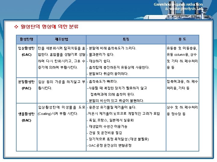
Greenhouse gases reduction & waste pyrolysis Lab. v 활성탄 제조공정 • Activated carbon is manufactured by first dehydrating and carbonizing the carbonaceous raw material. • Activation is completed during a controlled oxidation step in which the carbonized material is heated in the presence of an oxidizing gas. • For certain carbons, the dehydration can be accomplished by using chemical agents. • 활성화되지 char 만을 이용해서 유해가스를 처리하는 공정도 있으며 이때 사용하는 char는 대부분 lignite를 이 용한다. (lignite, subbitminous, anthracite-> ASTM 분류) • The ideal raw material has a porous structure that provides a uniform pore distribution and high adsorptive capacity when activated. • Activated carbon is tailored for specific end use by both raw material selection and control of the activation process. • Table 12. 1 lists some properties of various adsorbents used to treat polluted air. • Table 12. 2 lists some properties of various activated carbons.

Greenhouse gases reduction & waste pyrolysis Lab.

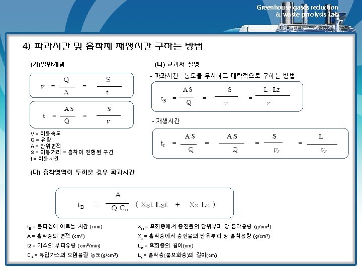
Greenhouse gases reduction & waste pyrolysis Lab. 12. 4 Fixed-Bed Adsorption Systems Breakthrough Curves and Their Relationship to System Design 1) 고정상 흡착반응의 진행 • The dynamics of fixed-bed adsorption are shown graphically in Figure 12. 4. • In the upper part of the figure, a fixed bed is shown at tree different times representing the interval from the initial admission of adsorbate to the time at which a significant concentration of adsorbate breaks through the bed • The plot in the lower half of the figure depicts the effluent concentration from the bed as a function of the volume of effluent, or time of operation • This type of plot is called a breakthrough curve, and provides valuable information on the adsorption rate in the bed ü 비약곡선(breakthrough curve) 고정상에서 유출되는 피흡착물의 농도를 운전시간 또는 유출용적의 함수로써 보여주는 그래프 ü 파과점 (breakthrough point) 오염가스가 흡착제로 유입되는 동안 시간이 경과함에 따라 흡착제에 흡착되지 못한 오염가스가 일부 배출되는 시점에 이른다. 이 시점은 흡착제가 피흡착물질을 흡착 제거할 수 있는 한계에 이른 상태로서 파과점이라고 한다. (일반적으로 유출농도가 입구농도의 5~10%에 달하는 시점으로서 한다. ) ü 종말점(end point) 파과점을 지난 이후부터는 배출가스의 중의 오염농도가 급격히 상승한다. 돌파곡선의 최고농도에 이른 시점을 종말점이라고 한다.

Greenhouse gases reduction & waste pyrolysis Lab.
 흡착영역과 효율 • During depletion of")
Greenhouse gases reduction & waste pyrolysis Lab. 2) 흡착영역과 효율 • During depletion of bed, an active adsorption zone(AZ) moves through the bed. • Behind the AZ, the adsorbent is saturated, whereas in front of the AZ, the bed is virtually free of adsorbate. • The length of the zone is a function of the rate of transfer of adsorbate from the gas to the adsorbent. • A shallow AZ indicates good adsorbent utilization and is represented by a steep breakthrough curve. • A wide of deep AZ denotes poor bed utilization and is indicated by a gradual slope on the breakthrough curve • The length of the AZ determines the minimum depth of the adsorbent bed 3) 활성탄 성능에 영향을 주는 요인 • Under actual plant operating conditions, bed capacity will seldom exceed 30 to 40% of that indicated by an equilibrium isotherm. • Factors that contribute to bed capacity loss are shown graphically in Figure 12. 5 • Curve a represents the bed adsorbate concentration indicated by an isotherm for the bed operating temperature. • In this case, the isotherm predicts a concentration of 30 g adsorbate/ 100 g carbon throughout the bed.

Greenhouse gases reduction 30 & waste pyrolysis Lab. v Bed capacity loss • A significant loss occurs because the bed must be taken out of service at or before the time that the leafing edge of the AZ exits the bed. • Since the adsorbent in the AZ is not saturated, the bed capacity is reduced by the area bounded by curve B. • The heat of adsorption liberated within the AZ passes through the bed, lowering the capacity as shown by curve C. • Moisture reduces the bed capacity by two mechanisms : moisture in the influent gas displaces adsorbate(shown by curve D). And residual moisture remaining in the bed after regeneration further occupies some additional bed volume(shown by curve E).

Greenhouse gases reduction 31 & waste pyrolysis Lab.

Greenhouse gases reduction & waste pyrolysis Lab. Pressure Drop Across Fixed Beds • Figure 12. 6 is a plot of pressure drop versus superficial bed velocity for several particle size. • The fan energy usage resulting from pressure drop is significant part of the overall operating cost of a fixed bed system • optimum bed velocity increases with bed depth over the normal operating range of 50 -100 ft/min Figure 12. 6 pressure drop across a carbon bed as a function of the superficial bed velocity and carbon mesh size
 is valid for")
Greenhouse gases reduction & waste pyrolysis Lab. ü Equation (12. 14) is valid for velocities of 60 -140 ft/min and bed Depths of 5 -50 inches, and for 4*6 mesh sized carbon.
 재생방법 • Material reversibly")
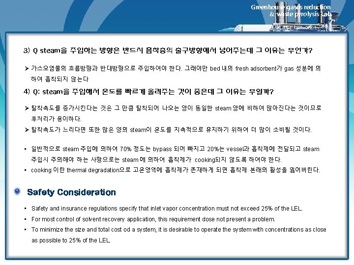
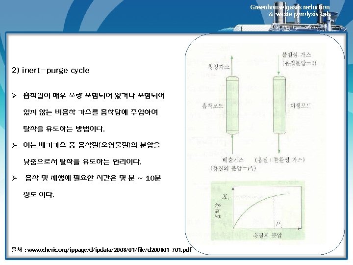
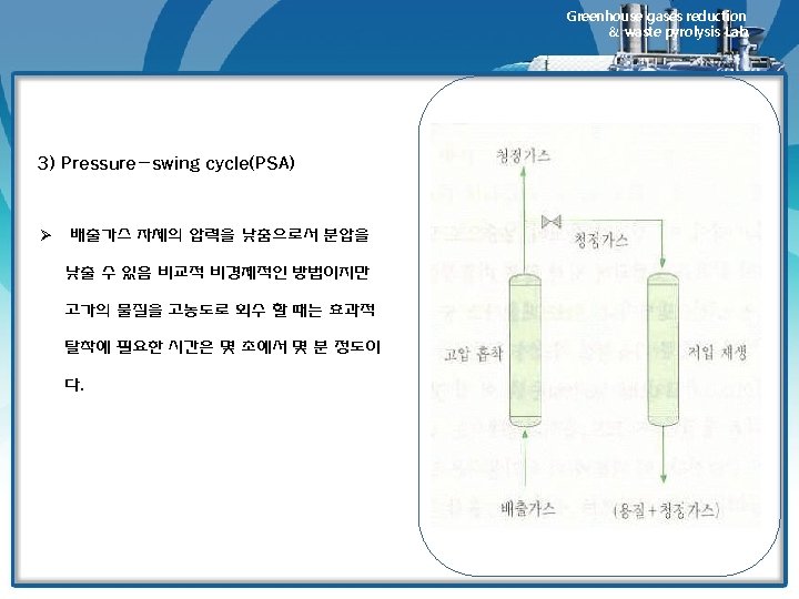
Greenhouse gases reduction & waste pyrolysis Lab. Adsorbent Regeneration 1) 재생방법 • Material reversibly adsorbed on carbon of other adsorbents can be removed by 1) Contact with a hot inert gas (air can be used if the adsorbate is noncombustible) 2) Contact with low-pressure steam (stripping) 3) Pressure reduction over the bed (pressure swing adsorption, PSA) • Method 1 and 2 are essentially same. However, for most solvents, stream regeneration is mush more effective than inert gas regeneration, which is used only in those where water would contaminate the recovered solvent either by chemical reaction of by formation of a mixture that is difficult to separate. • Regeneration by pressure reduction is not often economical in recovery or pollution control adsorption systems, but has been used in the recovery of gasoline vapor from tank-trick loading operation. 2) 필요한 steam양에 영향을 미치는 인자 • amount of carbon loading • bed geometry • ease of adsorbate removal • rule of thumb : 1~4 lbm steam/ lbm of adsorbates

Greenhouse gases reduction & waste pyrolysis Lab. 12. 5 Design of Fixed-Bed Carbon Adsorption Systems • The design and operation of a carbon adsorption (CA) system involves heat and mass transfer, fluid dynamics, process control, and chemical analysis. • In typical solvent recovery operations where adsorbate volatilities may be moderate (for VOCs with 8 -12 carbons) to high(for C 4 -C 7), the AZ length will vary from 0. 5 to 1. 5 feet • The actual geometry of the bed must such that the following three requirements are met : 1. the bed must contain a sufficient mass of adsorbent to provide a reasonable bed cycle time. 2. the superficial bed velocity must be high enough to provide satisfactory mass transfer rates, but low enough to allow a reasonable pressure drop. 3. the minimum bed depth must be greater than the length of one adsorption zone
 reported that in the case")
Greenhouse gases reduction & waste pyrolysis Lab. • Opgrande(1979) reported that in the case of one CA project, the following information was required by supplier : 1. purpose of the system 7. price of solvent 2. type of solvent 8. gas stream flow rates 3. whether the solvent was to be reused 9. cooling water availability, pressure, and temperature 4. type of operation 10. Electrical power availability, voltage cycles, and so forth 5. method of operation(continuous, batch. . ) 11. Stream availability, pressure, and so forth 6. gas stream composition, temperature, pressure, and humidity • After receiving the information, the suppliers submitted proposals specifying the following 1. operational details of the system 9. System total operation weight 2. materials of construction 10. Electrical requirements 3. cycle time 11. Stream requirements 4. operating conditions for the unit 12. Cooling water requirements 5. vessel size 13. Instrument air requirements 6. carbon supply 14. Instrumentation package description 7. recovery capacities 15. Cost and delivery, terms, and so forth 8. installation site size requirement 16. Pollution control guarantee

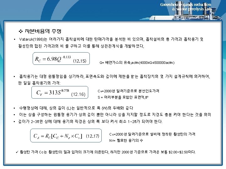
Greenhouse gases reduction & waste pyrolysis Lab. 12. 6 Economics of Fixed-Bed Adsorption Systems v Capital Cost Estimates In 1990, the delivered cost of a carbon-steel packing adsorber complete with fan , instrumentation, overhead codenser and cooler, and decanter was approximately $30/scfm Vatavuk reported that the purchase costs of package systems (for 350≤Mc ≤ 14000 can be estimated from the following relationship (12. 15) PEC = purchase cost, 1988 dollars Mc = mass of carbon in the system, lbm For larger , custm-designed units requiring more than 14000 pounds of carbon (12. 16) ü Typical grades of carbon have costs ranging from $2. 00 to $2. 50 per pound

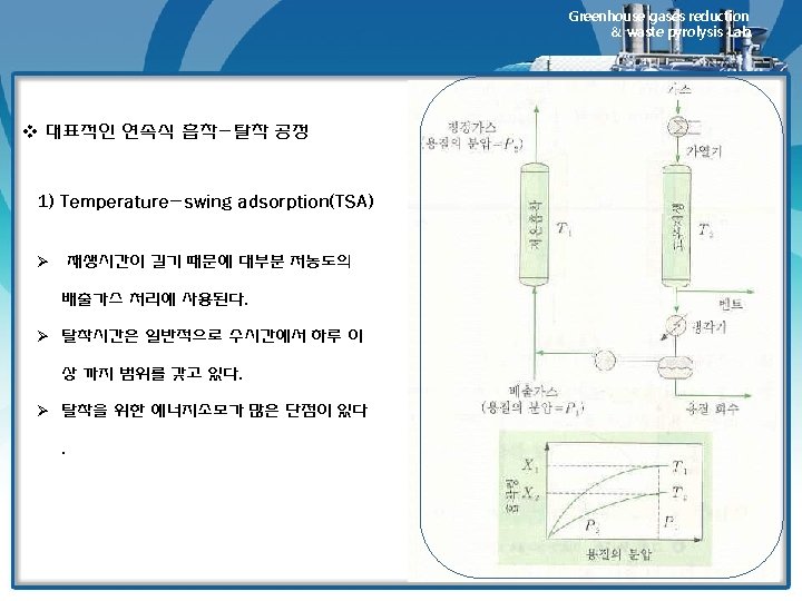
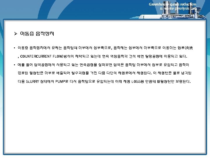
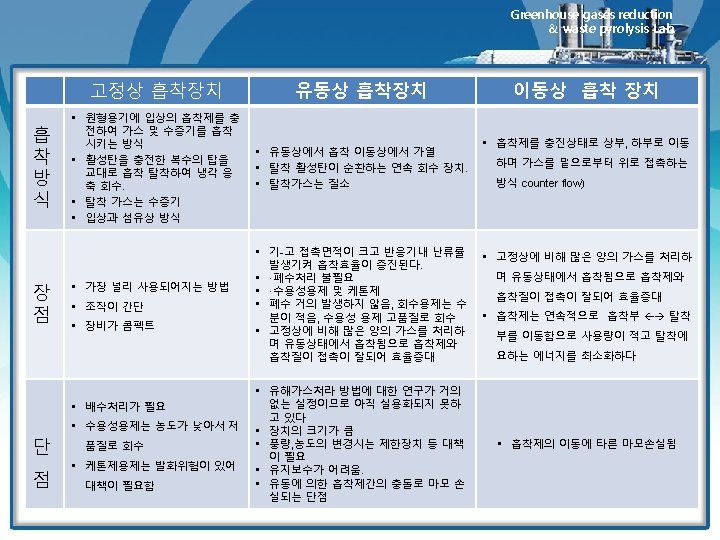
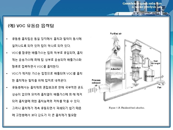
12. 7 Fluidized-Bed Adsorbers Greenhouse gases reduction & waste pyrolysis Lab. Ø 고정상 흡착장치 • 고정상 흡착장치에 필요한 흡착제의 주기적 가열과 냉각은 많은 스팀량을 필요로 함 • 고정상 설비와 관련된 기타 문제점으로는 불량한 스팀과 가스의 분 포상태 및 복잡한 배관 등을 필요로 함 Ø 유동상 흡착장치 • The most recently commercialized fluidized-bed adsorber is the Purasiv HR unit shown schematically in Figure 12. 8. • 장점: 가스와 고체의 접촉효과가 우수하고 주기적인 가열이 필요 없음 http: //www. youtube. com/watch? v=re-Nuv. ZAp 9 M Granulation Fluid Bed Drier 1
- Slides: 48