GRAPHICS PROGRAMMING Chapter 2 Computer Graphics and Visualization

")


 { initialize_the_system(); for (some_number_of_points) {")


![display function void display(void) { point 2 triangle[3] = {{0. 0, 0. 0}, {250.](https://slidetodoc.com/presentation_image_h/ca77ab3b20c46d02bbe846d0e0af7c78/image-15.jpg "display function void display(void) { point 2 triangle[3] = {{0. 0, 0. 0}, {250.")
![Contd… p[0] = (p[0] + triangle[j][0])/2; compute new point */ p[1] = (p[1] +](https://slidetodoc.com/presentation_image_h/ca77ab3b20c46d02bbe846d0e0af7c78/image-16.jpg "Contd… p[0] = (p[0] + triangle[j][0])/2; compute new point */ p[1] = (p[1] +")


: Open. GL function names begin with the")


 The line-segment type causes successive pairs of vertices to be")


 These objects are special cases of polygons. Successive groups")
 These objects are based on groups of triangles")
 For the quad_strip, two new vertices are combined")


 { phir=c*phi; phir 20=c*(phi+20); gl. Begin(GL_QUAD_STRIP); for")

; gl. Vertex 3 d(0. 0, -1. 0); z = -sin(c")

- Slides: 54
GRAPHICS PROGRAMMING Chapter 2 Computer Graphics and Visualization
Highlights of the chapter Programming oriented approach is used. Minimal application programmer's interface (API) is used which allow to program many interesting two- and three-dimensional problems, and to familiarize with the basic graphics concepts. 2 -D graphics is regarded as a special case of 3 -D graphics. Hence the 2 -D code will execute without modification on a 3 -D system. A simple but informative problem called: The Sierpinski gasket” is used. 2 -D programs that do not require user interaction can be written with knowledge presented here. The chapter is concluded with an example of a 3 -D application. in slides on Chapter 2 Adapted from Angel: Interactive Computer Graphics 5 E © Addison-Wesley 2009 2
The Sierpinski Gasket Problem The Sierpinski gasket is an object that can be defined recursively and randomly in the limit, however, it has properties that are not at all random Consider the three vertices in the plane. Assume that their locations, as specified in some convenient coordinate system, are (Xl, Y 1), (X 2, Y 2), and (X 3, Y 3). The construction proceeds as follows:
Construction of Gasket 1. Pick an initial point at random inside the triangle. 2. Select one of the three vertices at random. 3. Find the point half way between the initial point and the randomly selected vertex. 4. Display this new point by putting some sort of marker, such as a small circle, at its location. . 5. Replace the initial point with this new point. 6. Return to step 2. Thus, each time a point that is generated, it is displayed on the output device. In the figure p 0 is the initial point, and Pl and P 2 are the first two points generated by the algorithm.
A possible form for our graphics program main( ) { initialize_the_system(); for (some_number_of_points) { pt = generate_a_point(); display_the_point(pt); } cleanup(); }
Programming 2 -D applications To produce the image of a 3 -D object on 2 -D pad of penplotter model, the positions of 2 -D points corresponding to points on 3 -D object are to be specified. These two-dimensional points are the projections of points in three-dimensional space. The mathematical process of determining projections is an application of trigonometry. An API allows users to work directly in the domain of their problems, and to use computers to carry out the details of the projection process automatically, without the users having any trigonometric calculations within the application program
Contd… For 2 -D applications, such as the Sierpinski gasket, discussion is started with a three-dimensional world. Mathematically, a 2 -D plane or a simple 2 -D curved surface is viewed as a subspace of a threedimensional space. Hence, statements-both practical and abstract -about the bigger 3 -D world will hold for the simpler 2 -D one. We can represent a point in the plane z=0 as p = (x, y, 0) in 3 -D, or as p = (x, y) in 2 -D subspace corresponding to the plane.
Contd… In Open. GL, internal representation for both 2 -D and 3 -D points is same. Hence a 3 -D point is represented by a triplet: regardless of in what coordinate system p is represented. Vertex ( rather than point): A vertex is a location in space (in Computer Graphics a 2 -D, 3 -D, 4 -D spaces are used). Vertices are used to define the atomic geometric objects that are recognized by graphics system. The simplest geometric object is a point in space, which is specified by a single vertex. Two vertices define a line segment. Three vertices can determine either a triangle or a circle. Four vertices determine a quadrilateral, and so on.
Multiple Forms of functions Open. GL has multiple forms for many functions. The variety of forms allows the user to select the one best suited for the problem. General for of the vertex function is gl. Vertex* where the * can be interpreted as either two or three characters of the form nt or ntv, where -n signifies the number of dimensions (2, 3, or 4); -t denotes the data type, such as integer (i), float (f), or double (d); -v, if present, indicates the variables are specified through a pointer to an array, rather than through an argument list. Regardless of which form a user chooses, the underlying representation is the same.
Basic Open. GL types GLfloat and GLint, are used rather than the C types, such as float and int. These types are defined in the header files and usually in the obvious way-for example, #define GLfloat However, use of the Open. GL types allows additional flexibility for implementations for example, suppose the floats are to be changed to doubles without altering existing application programs.
Contd. . Returning to the vertex function, if the user wants to work in 2 -D with integers, then the form gl. Vertex 2 i(GLint xi, GLint yi) is appropriate gl. Vertex 3 f(GLfloat x, GLfloat y, GLfloat z) specifies a position in 3 -D space using floating-point numbers. If an array is used to store the information for a 3 -D vertex, GLfloat vertex[3] then gl. Vertex 3 fv(vertex) can be used.
Geometric primitives Different numbers of vertices are required depending on the object. Any number of vertices can be grouped using the functions gl. Begin and gl. End. The argument of gl. Begin specifies the geometric type that the vertices define. Hence, a line segment can be specified by gl. Begin(GL_LINES); gl. Vertex 2 f(xl, yl); gl. Vertex 2 f(x 2, y 2); gl. End();
Contd… Same data can be used to define a pair of points, by using the form, gl. Begin(GL_POINTS); gl. Vertex 2 f(xl, yl); gl. Vertex 2 f(x 2, y 2); gl. End();
Heart of Sierpinski gasket program Suppose that all points are to be generated within a 500 x 500 square whose lower left-hand corner is at (0, 0) - a convenient, but easily altered, choice. How to represent geometric data in program? A two-element array for 2 -D points is used: typedef GLfloat point 2[2]; A function called display, is created to generate 5000 points each time it is called. Assume that an array of triangle vertices triangle[3] is defined in display as an array of point 2.
display function void display(void) { point 2 triangle[3] = {{0. 0, 0. 0}, {250. 0, 500. 0}, {500. 0, 0. 0}}; /* an arbitrary triangle */ static point 2 p = {75. 0, 50. 0}; /* or set to any desired initial point */ int j, k; int rand(); /* standard randomnumber generator*/ for(k=0; k<5000; k++) { j = rand()%3; /* pick a random vertex from 0, 1, 2 */
Contd… p[0] = (p[0] + triangle[j][0])/2; compute new point */ p[1] = (p[1] + triangle[j][1])/2; gl. Begin(GL_POINTS); display new point */ gl. Vertex 2 fv(p) ; gl. End(); } gl. Flush(); } /* /*
The function rand is a standard random-number generator that produces a new random integer each time that it is called. Modulus operator is used to reduce these random integers to the three integers 0, 1, and 2. The call to gl. Flush ensures that points are rendered to the screen as soon as possible. If it is left, the program works correctly, but in a busy or networked environment there may be noticeable delay. A complete program is not yet written.
Figure below shows the expected output:
Issues leftwith 1. Color of drawing. 2. Position of the image on the screen. 3. Size of the image. 4. Window (area on the screen) for the image. 5. How much of the infinite pad will appear on the screen? 6. How long will the image remain on the screen? The basic code answering these questions and to control the placement and appearance of renderings will not change substantially across programs.
Coordinate Systems Graphics systems allow users to work in any desired coordinate system. The advent of device independent graphics freed application programmers from worrying about the details of input and output devices. World coordinate system or the Problem coordinate system: It is the user's coordinate system. Device Coordinates: Units on the display. E. g. For raster devices, such as most CRT displays, the term raster coordinates or screen coordinates is used. Raster coordinates are always expressed in some integer type, because the center of any pixel in the frame buffer must be located on a fixed grid, or, equivalently, because pixels are inherently discrete and they can be addressed using integers.
At some point, the values in world coordinates must be mapped into device coordinates, as shown in figure The graphics system, rather than the user, is responsible for this task, and the mapping is performed automatically as part of the rendering process. To define this mapping, the user needs to specify only a few parameters-such as the area of the world to be seen and the size of the display.
The Open. GL API Till now we saw – Heart of Sierpinski gasket program Need to know how To gain control over the appearance of the object on display To control the flow of the program To interact with the window system To specify primitives to be displayed
Why only Open. GL API Open. GL’s structure is similar to that of most modern APIs Java 3 D and Direct. X Any effort in learning Open. GL will carry over to other software systems Open. GL is easy to learn, it is nevertheless powerful It supports simple 2 -D and 3 -D programs as well as advanced rendering techniques Our primary goal is to study Computer Graphics We are using Open. GL API to attain that goal So will not mention all Open. GL functions
Graphics Functions Graphics package model can be viewed as a black box Black box - a term that engineers use to denote a system whose properties are described by only its inputs and outputs; nothing is known about its internal workings. Hence graphics system can be viewed as a box whose inputs are function calls from a user program (say measurements from input devices, such as the mouse and keyboard and possibly other input, such as messages from the operating system); outputs are primarily the graphics sent to the output devices.
Graphics functions contd… An API is defined through the functions in its library. A good API may contain hundreds of functions It is helpful to divide the functions into six groups by their functionality: 1. Primitive functions 2. Attribute functions 3. Viewing functions 4. Transformation functions 5. Input functions 6. Control functions 7. Query functions
Contd… The primitive functions define the low-level objects or atomic entities that the system can display. Depending on the API, the primitives can include points, line segments, polygons, pixels, text, and various types of curves and surfaces. If primitives are what of an API- the objects that can be displayed, then attributes are the how. That is, the attributes govern the way that a primitive appears on the display. Attribute functions perform operations ranging from choosing the color, to picking a pattern with which to fill the inside of a polygon, to selecting a type face for the titles on a graph.
Contd… Synthetic camera must be described to create an image. Its position and orientation in our world must be defined, and equivalent of a lens must also be selected. This process not only will fix the view, but also clip out objects that are too close or too far away. The viewing functions specify various views. One of the characteristics of a good API is that it provides the user with a set of transformation functions that carry out transformations of objects, such as rotation, translation, and scaling
Contd… For interactive applications, the API provides a set of input functions to deal with diverse forms of input that characterize modern graphics systems say functions to deal with devices such as keyboards, mice, and data tablets In any real application, the complexities of working in a multiprocessing multi-window environment (usually a network environment) may need to be handled. The control functions communicate with the window system, to initialize the programs, and to deal with any errors that take place during the execution of programs.
Query functions: They provide useful information of API that can be useful in an application. E. g. Camera parameters or values in the frame buffer. To write device-independent programs, the implementation of the API need to take care of differences between devices, such as how many colors are supported or the size of the display. There applications where some properties of the particular implementation need to be known. E. g. If the programmer knows in advance the display device at work supports only two colors rather than millions of colors, things the programmer chooses might be different. A good API provides this information through a set of query functions.
The Open. GL Interface GL (Graphics Library): Open. GL function names begin with the letters gl and are stored in a library usually referred to as GL. There a few related libraries: Graphics utility library (GLU): This library uses only GL functions, but contains code for common objects, such as spheres, that users prefer not to have to write repeatedly. This library is available in all Open. GL implementations. GL Utility Toolkit (GLUT): It addresses the problems of interfacing with the window system. It provides the minimum functionality that should be expected in any modern windowing system. System specific library is required for establishing interaction But instead of using a diff library every time, we use readily available GLUT – provides min functionality expected in any modern windowing system
Contd… Figure below shows the organization of the libraries for an X Window system environment. Note that various other libraries are called from the Open. GL libraries, but that the application program does not need to refer to these libraries directly. A similar organization holds for other environments, such as Microsoft Windows.
Contd. . Open. GL makes heavy use of macros to increase code readability and to avoid the use of magic numbers. Thus, strings such as GL_FILL and GL_POINTS are defined in header (. h) files. In most implementations, one of the include lines #include <GL/glut. h> or #include <glut. h> is sufficient to read in glut. h, gl. h, and glu. h.
Primitives and attributes Open. GL basic library has a small set of primitives an additional library, GLU, contains a richer set of objects derived from the basic library. Open. GL supports 2 classes of primitives: Geometric primitives Image or raster primitive Geometric primitives include points, line segments, polygons, curves and surfaces These primitives pass through a geometric pipeline, where they are subjected to a series of geometric operations Raster primitives, such as array of pixels, lack geometric properties and hence cannot be manipulated in same way
Primitives and attributes The basic Open. GL primitives are specified via points in space or vertices. Thus, the programmer defines objects with sequences of the form gl. Begin(type); gl. Vertex*(. . . ); gl. End(); The value of type specifies how Open. GL interprets the vertices to define geometric objects
Contd… Other code and Open. GL function calls can occur between gl. Begin and gl. End. E. g. Attributes can be changed or calculations can be performed for the next Vertex between gl. Begin and gl. End, or between two invocations of gl. Vertex A major conceptual difference between the basic geometric types is whether or not they have interiors. Aside from the point type, all the other basic types will be defined either in terms of vertices or by finite pieces of lines, called line segments Of course, a single line segment is itself specified by a pair of vertices
Contd… The line segment is of such importance that it can be considered a basic graphical entity. The use of line segments can be: To define approximations to curves. To connect data values for a graph. For the edges of closed objects, such as polygons, that have interiors.
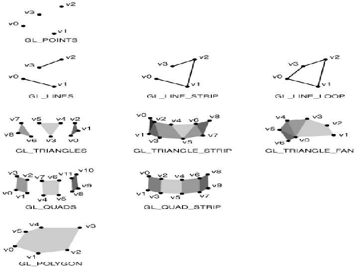
Line segments (GL_LINES) The line-segment type causes successive pairs of vertices to be interpreted as the endpoints of individual segments. Because the interpretation is done on a pair wise basis, successive segments usually are disconnected. Polylines (GL_LINE_STRIP) It is used if successive vertices (and line segments) are to be connected. Many curves can be approximated via a suitable polyline. GL_LINE_LOOP: If the polyline need to be closed the final vertex is located in the same place as the first, or GL_LINE_LOOP can be used which will draw a line segment from the final vertex to the first, thus creating a closed path.
Polygon Basics Line segments and polylines can model the edges of objects, but closed objects also may have interiors as shown in figure Polygon refers to an object that has a border that can be described by a line loop, but has an interior. Polygons play a special role in computer graphics because they can be displayed rapidly and they can be used to approximate arbitrary or curved surfaces. The performance of graphics systems is measured by the number of polygons per second that can be displayed.
Ways of displaying polygons Only its edges be displayed. Its interior be filled with a solid color, or a pattern Either display or not display the edges. Outer edges of a polygon can be defined easily by an ordered list of vertices. But if the interior is not well defined, then the polygon may be rendered incorrectly.
Three properties of a polygon Three properties will ensure that a polygon will be displayed correctly: It must be simple, convex, and flat. Simple: A 2 -D polygon in which no pair of edges cross each other. They will have well-defined interiors. Although the locations of the vertices determine whether or not a polygon is simple, the cost of testing is sufficiently high that most graphics systems require that the application program do any necessary testing. Non-simple: Graphics system must handle by some means if a non-simple polygon is to be displayed and to define an interior for a nonsimple polygon.
Convex An object is convex if all points on the line segment between any two points inside the object, or on its boundary, are inside the object regardless of the type of the object and its dimension (whether 2 -D or 3 -D). Convex objects include triangles, tetrahedra, rectangles, circles, spheres, and parallelepipeds. There are various tests for convexity. However, like simplicity testing, convexity testing is expensive and usually is left to the application program.
Convex objects
Flat In 3 -D, polygons present a few more difficulties, because, unlike all 2 -D objects, they are not necessarily flat i. e. , all vertices that define polygon need not lie in the same plane. One property that most graphics systems exploit, and that can be used, is that any three vertices that are not collinear determine both a triangle and the plane in which that triangle lies. Hence, the use of only triangles is safe in rendering such objects correctly.
Polygon types in Open. GL For objects with interiors, we can specify following types Polygons (GL_POLYGON): Successive vertices define line segments, and a line segment connects the final vertex to the first. The interior is filled according to the state of the relevant attributes. Note that a mathematical polygon has an inside and an outside that are separated by the edge. The edge itself has no width. Consequently, most graphics systems allow to fill the polygon with a color or pattern or to draw lines around the edges, but not to do both. In Open. GL, gl. Polygon. Mode function can be used to select edges instead of fill (the default). However, to draw a filled polygon and to display its edges, it must be drawn twice, once in each mode, or a polygon and a line loop with the
Triangles and Quadrilaterals (GL_TRIANGLES, GL_QUADS) These objects are special cases of polygons. Successive groups of three and four vertices are interpreted as triangles and quadrilaterals, respectively. Using these types may lead to a rendering more efficient than that obtained with polygons.
Strips and Fans (GLTRIANGLE_STRIP, GL_QUAD_STRIP, GL_TRIANGLE_FAN) These objects are based on groups of triangles or quadrilaterals that share vertices and edges. In the triangle_strip, for example, each additional vertex is combined with the previous two vertices to define a new triangle.
Strips and Fans (GLTRIANGLE_STRIP, GL_QUAD_STRIP, GL_TRIANGLE_FAN) For the quad_strip, two new vertices are combined with the previous two vertices to define a new quadrilateral. A triangle fan is based on one fixed point. The next two points determine the first triangle, and subsequent triangles are formed from one new point, the previous point, and the first (fixed) point.
Approximating a Sphere Many curved surfaces can be approximated using fans and strips. E. g. To approximate to a sphere, a set of polygons defined by lines of longitude and latitude as shown can be used. Either quad strips or triangle strips can be used for the purpose. Consider a unit sphere. It can be described by the following three equations: x(θ, Ø)= sinθ cosØ , y(θ, Ø)= cosθ cosØ, z(θ, Ø) = sinØ.
Contd… Circles of constant longitude can be obtained by fixing θ and varying Ø. Likewise, circles of constant latitude can be obtained by fixing Ø and varying θ. Quadrilaterals can be defined by generating points at fixed increments of θ. Degrees must be converted to radians for the standard trigonometric functions. The code for the quadrilaterals corresponding to increments of 20 degrees in θ and to 20 degrees in Ø is, given below:
code for(phi=-80. 0; phi<=80. 0; phi+=20. 0) { phir=c*phi; phir 20=c*(phi+20); gl. Begin(GL_QUAD_STRIP); for (theta=-180. 0; theta<=180. 0; theta+=20. 0) { thetar=c*theta; x=sin(thetar)*cos(phir); y=cos(thetar)*cos(phir); z=sin(phir); gl. Vertex 3 d(x, y, z); x=sin(thetar)*cos(phir 20); y=cos(thetar)*cos(phir 20); z=sin(phir 20); gl. Vertex 3 d(xty, z); } gl. End( ); }
Contd… But strips can not be used at the poles, because all lines of longitude converge there. Instead two triangle fans one at each pole can be used, as follows: gl. Begin(GL_TRIANGLE_FAN); gl. Vertex 3 d(0. 0, 1. 0); c=M_PI/180. 0; c 80=c*80. 0; z=sin(c 80); for(thet=-180. 0; theta<=180. 0; theta += 20. 0) { thetar=c*theta; x=sin(thetar)*cos(c 80); y=cos(thetar)*cos(c 80); gl. Vertex 3 d(x, y, z); } gl. End( );
Contd. . gl. Begin(GL_TRIANGLE_FAN); gl. Vertex 3 d(0. 0, -1. 0); z = -sin(c 80); for(theta=-180. 0; theta<=180. 0; theta += 20. 0) { thetar=c*theta; x=sin(thetar)*cos(c 80); y=cos(thetar)*cos(c 80); gl. Vertex 3 d(x, y, z); } gl. End( );
Text In computer graphics text may need to be displayed in a multitude of fashions by controlling type styles, sizes, colors, and other parameters. (Note that in non graphical applications, a simple set of characters, are displayed in the same manner). Graphics applications must provide a choice of fonts. Fonts are families of type faces of a particular style, such as Times, Computer Modern, or Helvetica.