
Grade 10 Forces Pushing or Pulling Forces You
- Slides: 31
Grade 10 Forces
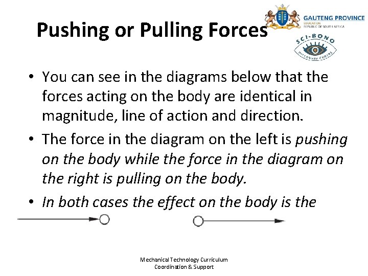
Pushing or Pulling Forces • You can see in the diagrams below that the forces acting on the body are identical in magnitude, line of action and direction. • The force in the diagram on the left is pushing on the body while the force in the diagram on the right is pulling on the body. • In both cases the effect on the body is the same. Mechanical Technology Curriculum Coordination & Support
Mechanical Technology Curriculum Coordination & Support
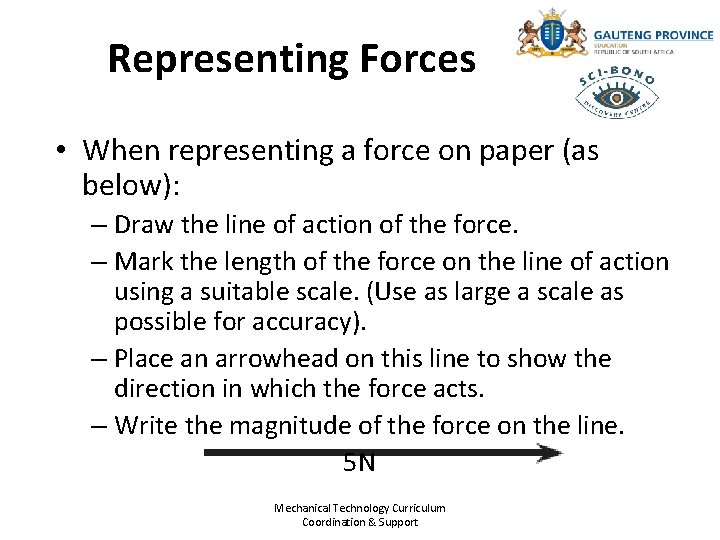
Representing Forces • When representing a force on paper (as below): – Draw the line of action of the force. – Mark the length of the force on the line of action using a suitable scale. (Use as large a scale as possible for accuracy). – Place an arrowhead on this line to show the direction in which the force acts. – Write the magnitude of the force on the line. 5 N Mechanical Technology Curriculum Coordination & Support
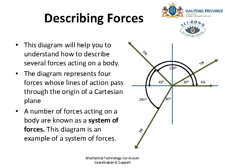
Describing Forces 6 N 5 N 1350 450 2400 7 N • This diagram will help you to understand how to describe several forces acting on a body. • The diagram represents four forces whose lines of action pass through the origin of a Cartesian plane • A number of forces acting on a body are known as a system of forces. This diagram is an example of a system of forces. Mechanical Technology Curriculum Coordination & Support 300 4 N
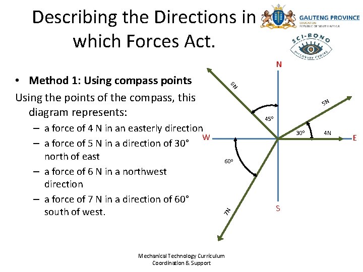
Describing the Directions in which Forces Act. N 5 N 450 300 600 7 N – a force of 4 N in an easterly direction W – a force of 5 N in a direction of 30° north of east – a force of 6 N in a northwest direction – a force of 7 N in a direction of 60° south of west. 6 N • Method 1: Using compass points Using the points of the compass, this diagram represents: Mechanical Technology Curriculum Coordination & Support S 4 N E
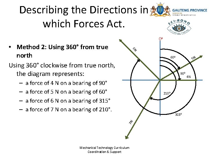
Describing the Directions in which Forces Act. 00 600 5 N 900 a force of 4 N on a bearing of 90° a force of 5 N on a bearing of 60° a force of 6 N on a bearing of 315° a force of 7 N on a bearing of 210°. 2100 3150 7 N – – 6 N • Method 2: Using 360° from true north Using 360° clockwise from true north, the diagram represents: Mechanical Technology Curriculum Coordination & Support 4 N
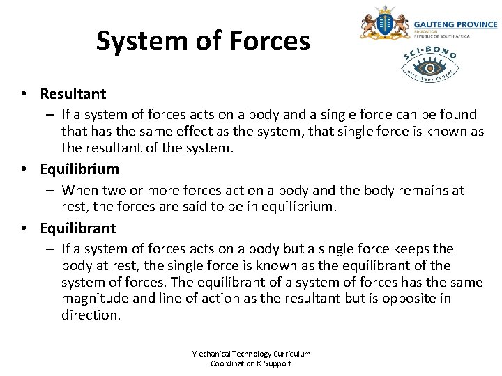
System of Forces • Resultant – If a system of forces acts on a body and a single force can be found that has the same effect as the system, that single force is known as the resultant of the system. • Equilibrium – When two or more forces act on a body and the body remains at rest, the forces are said to be in equilibrium. • Equilibrant – If a system of forces acts on a body but a single force keeps the body at rest, the single force is known as the equilibrant of the system of forces. The equilibrant of a system of forces has the same magnitude and line of action as the resultant but is opposite in direction. Mechanical Technology Curriculum Coordination & Support
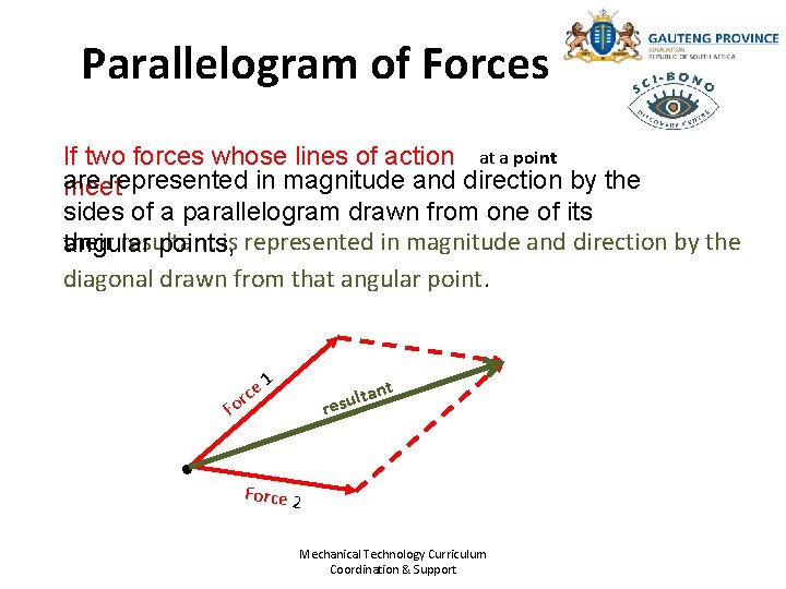
Parallelogram of Forces If two forces whose lines of action at a point are represented in magnitude and direction by the meet sides of a parallelogram drawn from one of its their resultant is represented in magnitude and direction by the angular points, diagonal drawn from that angular point. ce r Fo 1 nt lta u s e r Force 2 Mechanical Technology Curriculum Coordination & Support
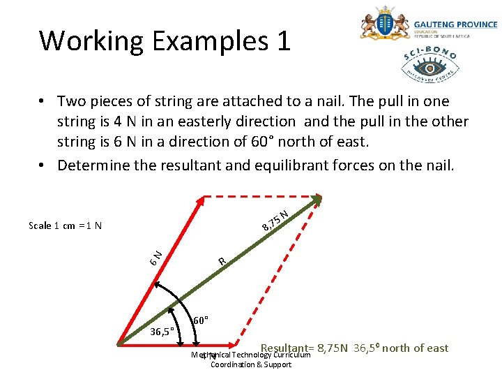
Working Examples 1 • Two pieces of string are attached to a nail. The pull in one string is 4 N in an easterly direction and the pull in the other string is 6 N in a direction of 60° north of east. • Determine the resultant and equilibrant forces on the nail. 5 8, 7 6 N Scale 1 cm = 1 N 36, 5° N R 60° Resultant= 8, 75 N 36, 50 north of east Mechanical 4 N Technology Curriculum Coordination & Support
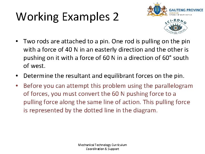
Working Examples 2 • Two rods are attached to a pin. One rod is pulling on the pin with a force of 40 N in an easterly direction and the other is pushing on it with a force of 60 N in a direction of 60° south of west. • Determine the resultant and equilibrant forces on the pin. • Before you can attempt this problem using the parallelogram of forces, you must convert the 60 N pushing force to a pulling force along the same line of action. This pulling force is represented by the dotted line in the diagram. Mechanical Technology Curriculum Coordination & Support
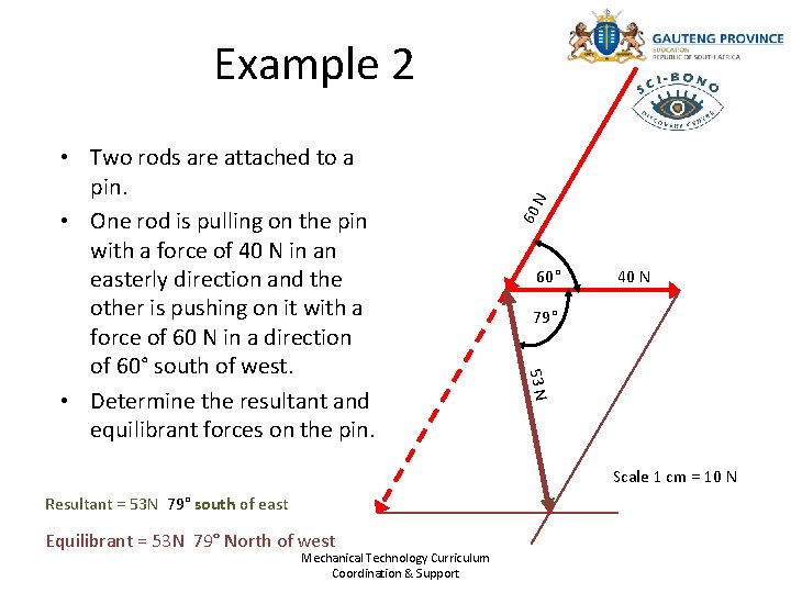
60 60° 40 N 79° 53 N • Two rods are attached to a pin. • One rod is pulling on the pin with a force of 40 N in an easterly direction and the other is pushing on it with a force of 60 N in a direction of 60° south of west. • Determine the resultant and equilibrant forces on the pin. N Example 2 Scale 1 cm = 10 N Resultant = 53 N 79° south of east Equilibrant = 53 N 79° North of west Mechanical Technology Curriculum Coordination & Support
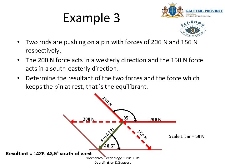
Example 3 • Two rods are pushing on a pin with forces of 200 N and 150 N respectively. • The 200 N force acts in a westerly direction and the 150 N force acts in a south-easterly direction. • Determine the resultant of the two forces and the force which keeps the pin at rest, that is the equilibrant. 15 0 N 135° 200 N 15 0 R= 14 2 N 200 N 48, 5° Resultant = 142 N 48, 5° south of west Mechanical Technology Curriculum Coordination & Support N Scale 1 cm = 50 N
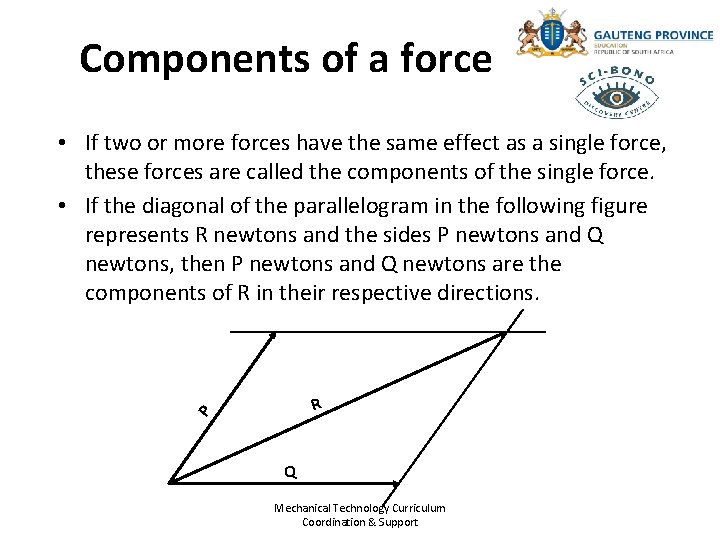
Components of a force • If two or more forces have the same effect as a single force, these forces are called the components of the single force. • If the diagonal of the parallelogram in the following figure represents R newtons and the sides P newtons and Q newtons, then P newtons and Q newtons are the components of R in their respective directions. P R Q Mechanical Technology Curriculum Coordination & Support
Introduction to triangle of forces • In the previous section you learnt how to graphically determine the resultant and equilibrant of two forces (whose magnitude and direction were known), by means of the parallelogram of forces. • Although useful, this method is limited to solving problems with only two forces. • When a system of forces contains three forces, we make use of a triangle of forces. Mechanical Technology Curriculum Coordination & Support
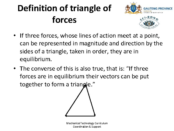
Definition of triangle of forces • If three forces, whose lines of action meet at a point, can be represented in magnitude and direction by the sides of a triangle, taken in order, they are in equilibrium. • The converse of this is also true, that is: “If three forces are in equilibrium their vectors can be put together to form a triangle. ” Mechanical Technology Curriculum Coordination & Support
Bow’s notation • Bow’s notation is a method which can be used to simplify problem solving where three or more forces are applied to a body in a system of forces. • The following system of forces contains three forces. • We will use Bow’s notation to construct a triangle of forces and show that they are in equilibrium. – Part 1: Construct a space diagram – Part 2: Construct a force diagram Mechanical Technology Curriculum Coordination & Support
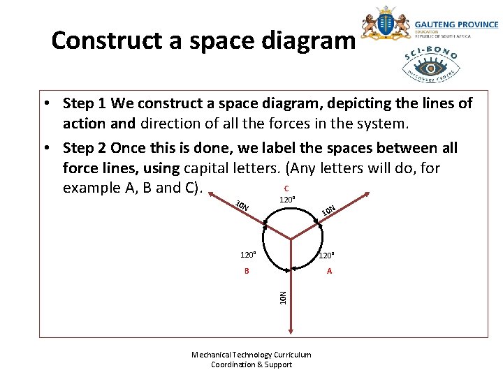
Construct a space diagram • Step 1 We construct a space diagram, depicting the lines of action and direction of all the forces in the system. • Step 2 Once this is done, we label the spaces between all force lines, using capital letters. (Any letters will do, for C example A, B and C). 10 N 120° 10 N 120° A 10 N B Mechanical Technology Curriculum Coordination & Support
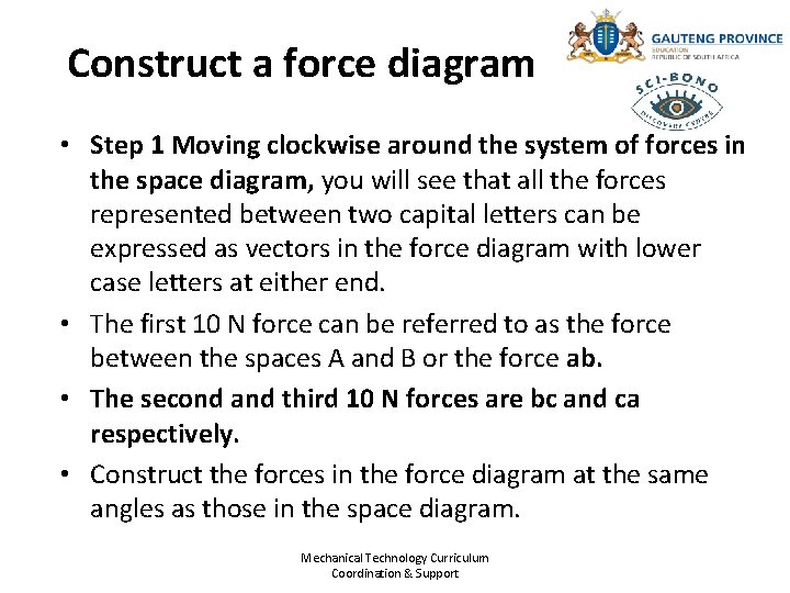
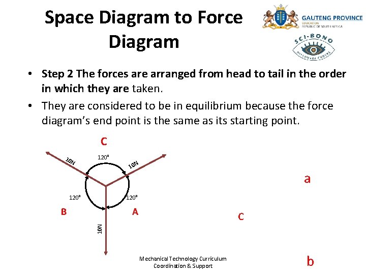
Construct a force diagram • Step 1 Moving clockwise around the system of forces in the space diagram, you will see that all the forces represented between two capital letters can be expressed as vectors in the force diagram with lower case letters at either end. • The first 10 N force can be referred to as the force between the spaces A and B or the force ab. • The second and third 10 N forces are bc and ca respectively. • Construct the forces in the force diagram at the same angles as those in the space diagram. Mechanical Technology Curriculum Coordination & Support
Space Diagram to Force Diagram • Step 2 The forces are arranged from head to tail in the order in which they are taken. • They are considered to be in equilibrium because the force diagram’s end point is the same as its starting point. C 10 N 120° 10 N a 120° A c 10 N B Mechanical Technology Curriculum Coordination & Support b
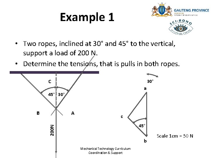
Example 1 • Two ropes, inclined at 30° and 45° to the vertical, support a load of 200 N. • Determine the tensions, that is pulls in both ropes. C 30° a 45° 30° A c 45° 200 N B b Mechanical Technology Curriculum Coordination & Support Scale 1 cm = 50 N
Example 1 • Measuring lines bc and ca and using the scale, we find that the tension in the ropes are as follows: – Rope bc represents a pulling force of 104 N in a direction of 45° north of west. – Rope ca represents a pulling force of 147 N in a direction of 60° north of east. Mechanical Technology Curriculum Coordination & Support
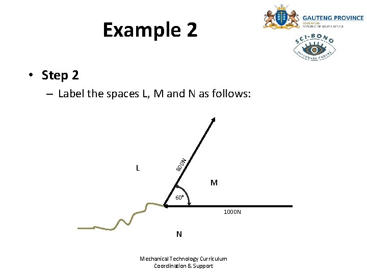
Example 2 • The following space diagram shows two rods which are joined to a pin. • The angle between the rods is 60°. • The horizontal rod is pushing with a force of 1 000 N in a westerly direction. • The inclined rod is pulling with a force of 800 N in a direction of 60° north of east. • Determine the force exerted by the pin, that is the equilibrant. Mechanical Technology Curriculum Coordination & Support
Example 2 • We will now introduce a method to help us find the unknown force, or equilibrant. • Step 1 – Draw the space diagram. – Nothing as yet is known about the third force (the equilibrant), so indicate it in the space diagram as a curly line. – Do this so that you can label the space diagram. Mechanical Technology Curriculum Coordination & Support
Example 2 • Step 2 80 L 0 N – Label the spaces L, M and N as follows: M 60° 1000 N N Mechanical Technology Curriculum Coordination & Support
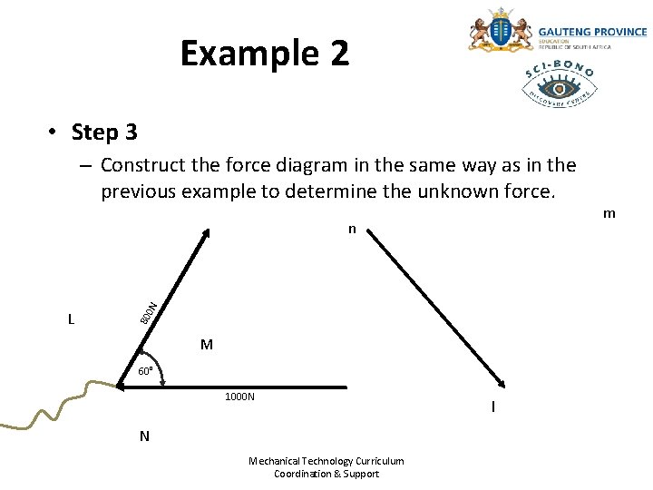
Example 2 • Step 3 – Construct the force diagram in the same way as in the previous example to determine the unknown force. 80 L 0 N n M 60° 1000 N N Mechanical Technology Curriculum Coordination & Support l m
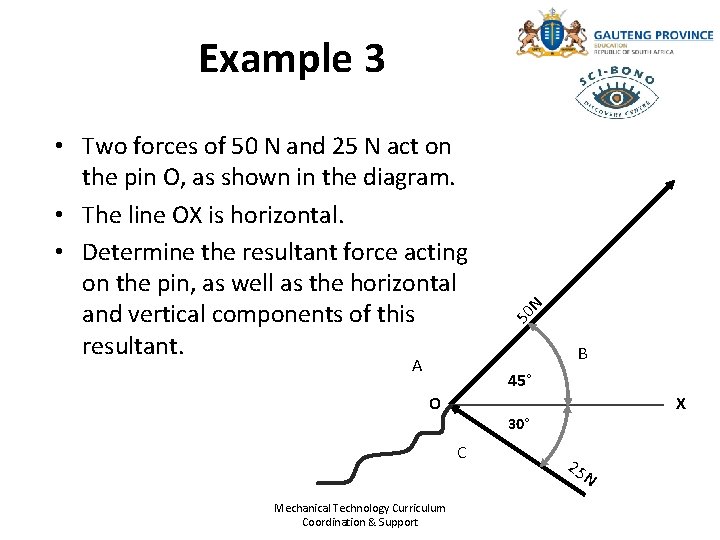
• Two forces of 50 N and 25 N act on the pin O, as shown in the diagram. • The line OX is horizontal. • Determine the resultant force acting on the pin, as well as the horizontal and vertical components of this resultant. A 50 N Example 3 B 45° O X 30° C Mechanical Technology Curriculum Coordination & Support 25 N
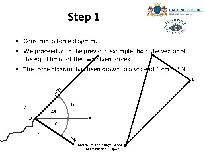
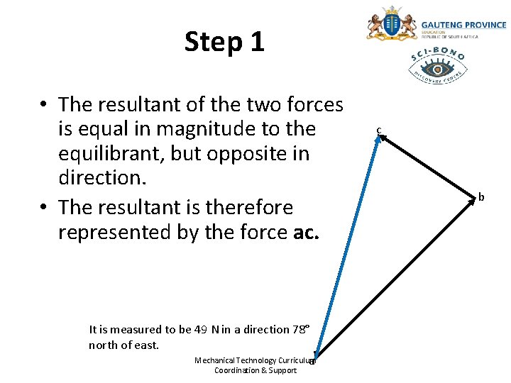
Step 1 • Construct a force diagram. • We proceed as in the previous example; bc is the vector of c the equilibrant of the two given forces. • The force diagram has been drawn to a scale of 1 cm = 2 N 50 N b B A 45° O X 30° C 25 N Mechanical Technology Curriculum a Coordination & Support
Step 1 • The resultant of the two forces is equal in magnitude to the equilibrant, but opposite in direction. • The resultant is therefore represented by the force ac. It is measured to be 49 N in a direction 78° north of east. Mechanical Technology Curriculum a Coordination & Support c b
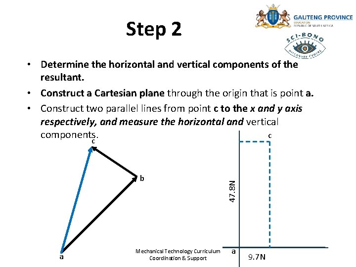
Step 2 b a Mechanical Technology Curriculum Coordination & Support 47. 8 N • Determine the horizontal and vertical components of the resultant. • Construct a Cartesian plane through the origin that is point a. • Construct two parallel lines from point c to the x and y axis respectively, and measure the horizontal and vertical c components. c a 9. 7 N
Step 2 • We will find: – The horizontal component is 9, 7 N. – The vertical component is 47, 8 N. • You could probably have worked out some of the above examples using the parallelogram of forces. • However, it is essential to be familiar with the use of the triangle of forces method, and Bow’s notation. Mechanical Technology Curriculum Coordination & Support