GPIO Burhan Barakl ki ynl Giri 7 admda

GPIO Burhan Baraklı

İki yönlü

Giriş

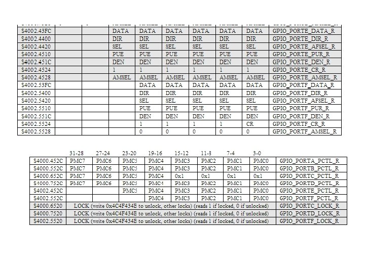
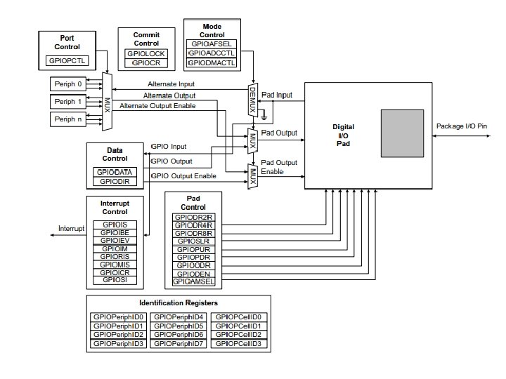
7 adımda i/o PF için 1. Portun Clock’unu aktifleştir. SYSCTL_RCGC 2_R |= 0 x 00000020; // 1) activate clock for Port F 2. Kilitin açılması gereken pinler PC 3 -0, PD 7, PF 0 GPIO_PORTF_LOCK_R = 0 x 4 C 4 F 434 B; // 2) unlock GPIO Port F 3. Analog girişi veya çıkışı iptal et. GPIO_PORTF_AMSEL_R = 0 x 00; // 3) disable analog on PF 4. GPIO fonksiyonleştirmeyi ayarla. GPIO_PORTF_PCTL_R = 0 x 0000; // 4) PCTL GPIO on PF 4 -0 5. Yönü belirt input veya output. GPIO_PORTF_DIR_R = 0 x 0 E; // 5) PF 4, PF 0 in, PF 3 -1 out 6. Geri kalan alternatif fonksiyonları kapat. GPIO_PORTF_AFSEL_R = 0 x 00; // 6) disable alt funct on PF 7 -0 7. Giriş çıkışları aktif et. GPIO_PORTF_DEN_R = 0 x 1 F; // 7) enable digital I/O on PF 4 -0
 activate")
PA 7 out • • SYSCTL_RCGC 2_R |= 0 x 00000001; // 1) activate clock for Port A delay = SYSCTL_RCGC 2_R; // allow time for clock to start GPIO_PORTA_AMSEL_R &= ~0 x 80=0 x 9 F // 3) disable analog on PA 7 GPIO_PORTA_PCTL_R &= ~0 x. F 0000000; // 4) PCTL GPIO on PA 7 GPIO_PORTA_DIR_R |= 0 x 80; // 5) PA 7 out GPIO_PORTA_AFSEL_R &= ~0 x 80; // 6) disable alt funct on PA 7 GPIO_PORTA_DEN_R |= 0 x 80; // 7) enable digital I/O on PA 7

Bit adresleme 4*2 b İlgilen bit PORTA nın 1, 2, 3 pinleriyle ilgilenelim. 0 x 4000+0 x 0008+0 x 0010 +0 x 0020= 0 x 4000. 4038 adresi okunursa pin 1, 2, 3 okunur. Yada bu adrese bir data yazılırsa 1, 2, 3 pinlerine yazılır.

base address for Port A is 0 x 4000 PORTA daki 8 biti okumak istiyorsak sabit sayımız => 0 x 03 FC =>0 x 4000. 43 FC Diğer bir deyişle GPIO_PORTA_DATA_R gibi okuyup yazarız. Eğer 5. pin ile ilgileniyorsak 0 x 0080 =>> 0 x 4000===0 x 40004080 #define PA 5 (*((volatile unsigned long *)0 x 40004080)) PA 5 EQU 0 x 40004080 PA 5 = 0 x 20; // make PA 5 high PA 5 = 0 x 00; // make PA 5 low PA 5 = PA 5^0 x 20; // toggle PA 5 Profesyonel olanı tabiki pointer kavramı
{ unsigned long volatile delay; SYSCTL_RCGC")
Yapılacak Ödev 1 unsigned long in, out; int main(void){ unsigned long volatile delay; SYSCTL_RCGC 2_R |= 0 x 08; // Port D clock delay = SYSCTL_RCGC 2_R; // wait 3 -5 bus cycles GPIO_PORTD_DIR_R |= 0 x 08; // PD 3 output GPIO_PORTD_DIR_R &= ~0 x 01; // PD 0 input GPIO_PORTD_AFSEL_R &= ~0 x 09; // not alternative GPIO_PORTD_AMSEL_R &= ~0 x 09; // no analog GPIO_PORTD_PCTL_R &= ~0 x 0000 F 00 F; // bits for PD 3, PD 0 GPIO_PORTD_DEN_R |= 0 x 09; // enable PD 3, PD 0 while(1){ in = (GPIO_PORTD_DATA_R&0 x 01); // in 0 if not pressed, 1 if pressed out = (in^0 x 01)<<3; // out 8 if not pressed, 0 if switch pressed GPIO_PORTD_DATA_R = out; } }
")
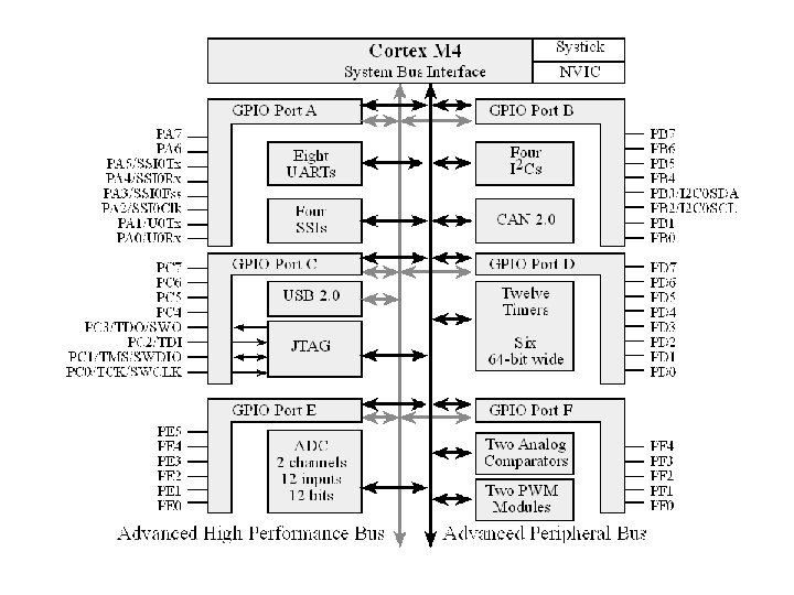
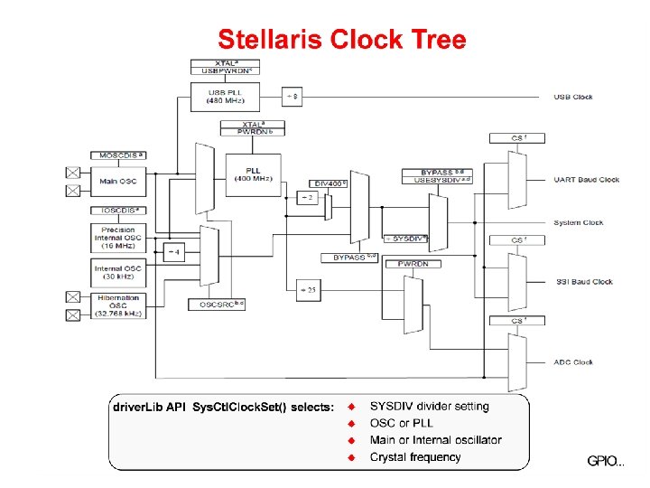
Saat Kaynakları • 4 tane sat kaynağı var. • 1. Hassas dahili osilatör (PIOSC) 16 MHZ+-%3 – Harici kristale ihtiyaç yoktur. • 2. MOSC – Ana osilatör • 3. Dahili 30 khz osilatör – Uyku modunda kullanılır. • 4. Hibernation saati – 32768 hertz – real time clock source.

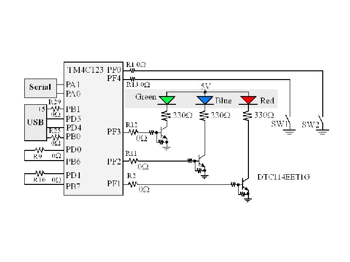
Kırmızı ledi yak ve söndür #include "inc/lm 4 f 120 h 5 qr. h" void wait(void); int main() { // General-Purpose Input/Output Run Mode Clock Gating Control (RCGCGPIO), pg. 315 SYSCTL_RCGCGPIO_R |= 0 x 20 U; // activate the clock for port f // GPIO Lock (GPIOLOCK), pg. 645 GPIO_PORTF_LOCK_R = 0 x 4 C 4 F 434 BU; // unlock the lock register // GPIO Commit (GPIOCR), pg. 646 GPIO_PORTF_CR_R = 0 x. FF; // enaomble cmit for PORT F // GPIO Analog Mode Select (GPIOASMSEL), pg. 648 GPIO_PORTF_AMSEL_R = 0 x 00 U; // disable analog functionality // GPIO Port Control (GPIOPCTL), pg. 649 GPIO_PORTF_PCTL_R = 0 x 0000 U; // configure port f as GPIO // GPIO Direction (GPIODIR), pg. 624 GPIO_PORTF_DIR_R = 0 x 0 EU; // 0 x. E = 01110 make PF 3, PF 2, and PF 1 output // GPIO Alternate Function Select (GPIOAFSEL), pg. 633 GPIO_PORTF_AFSEL_R = 0 x 00 U; // disable alternate functions // GPIO Digital Enable (GPIODEN), pg. 643 GPIO_PORTF_DEN_R = 0 x. FFU; // enable digital on all pins in PORTF while(1) { GPIO_PORTF_DATA_R &= ~0 x 0 E; // 0 E = 00001110, so ~0 E = 11110001 turn off the three leds wait(); GPIO_PORTF_DATA_R |= 0 x 02; // turn on the red led wait(); } return 0; } void wait(void) { int a, i; for(i=0; i<1000000; i++); }

Sw 1 -2 -3 ve Led Örneği #include "inc/lm 4 f 120 h 5 qr. h" int main() { // General-Purpose Input/Output Run Mode Clock Gating Control (RCGCGPIO), pg. 315 SYSCTL_RCGCGPIO_R |= 0 x 20 U; // activate the clock for port f // GPIO Lock (GPIOLOCK), pg. 645 GPIO_PORTF_LOCK_R = 0 x 4 C 4 F 434 BU; // unlock the lock register // GPIO Commit (GPIOCR), pg. 646 GPIO_PORTF_CR_R = 0 x. FF; // enable commit for PORT F // GPIO Analog Mode Select (GPIOASMSEL), pg. 648 GPIO_PORTF_AMSEL_R = 0 x 00 U; // disable analog functionality // GPIO Port Control (GPIOPCTL), pg. 649 GPIO_PORTF_PCTL_R = 0 x 0000 U; // configure port f as GPIO // GPIO Direction (GPIODIR), pg. 624 GPIO_PORTF_DIR_R = 0 x 0 EU; // 0 x. E = 01110 make PF 0 and PF 4 input, make PF 3, PF 2, and PF 1 output // GPIO Alternate Function Select (GPIOAFSEL), pg. 633 GPIO_PORTF_AFSEL_R = 0 x 00 U; // disable alternate functions // GPIO Pull-Up Select (GPIOPUR), pg. 638 GPIO_PORTF_PUR_R = 0 x 11 U; // 0 x 11 = 0001 enable pull up resistors on PF 0(SW 2) and PF 4 (SW 1) // GPIO Digital Enable (GPIODEN), pg. 643 GPIO_PORTF_DEN_R = 0 x. FFU; // enable digital on all pins in PORTF while(1) { GPIO_PORTF_DATA_R &= ~0 x 0 E; // 0 E = 00001110, so ~0 E = 11110001 turn off the three leds switch(GPIO_PORTF_DATA_R & 0 x 11 U) // 0 x 11 = 0001 { case 0 x 00: //both switches are pressed GPIO_PORTF_DATA_R |= 0 x 02; // turn on the red led break; case 0 x 01: //SW 1 is pressed, SW 2 is not pressed GPIO_PORTF_DATA_R |= 0 x 04; // turn on the blue led break; case 0 x 10: // SW 2 is pressed, SW 1 is not pressed GPIO_PORTF_DATA_R |= 0 x 08; // turn on the green led break; default: // 0 x 11 , neither switch is pressed // don't do anything break; } } return 0; }

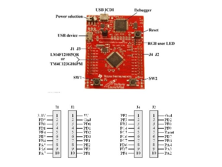
Api Örneği Blink 1 Step 1 - Set up System Clock Sys. Ctl. Clock. Set(SYSCTL_SYSDIV_5|SYSCTL_USE_PLL|SYSCTL_XTAL_16 MHZ|SYSCTL_OSC_MAIN); We need to generate a system clock of 40 MHz. We know that the input clock frequency after system prescale is 200 MHz SYSCTL_USE_PLL - this macro is used to specify that we are using the PLL to generate the 400 MHz clock frequency. SYSCTL_XTAL_16 MHz - This says to the u. C that we give the input to the PLL from an external crystal(XTAL) of frequency 16 MHz. SYSCTL_OSC_MAIN - This denotes that we are using an external main oscillator ( Again represents the 16 MHz crystal ). Now we know that all these are to be done together, and that is the reason why we logically OR all the macros. ##NOTE - Generally inside a function whose name starts with Sys. Ctl, the macro names will start with "SYSCTL_". This will help you in selecting the correct macro most of the time.
; Sys. Ctl. Peripheral. Enable(SYSCTL_PERIPH_GPIOA);")
Step 2 - Enable the GPIO Sys. Ctl. Peripheral. Enable(SYSCTL_PERIPH_GPIOF); Sys. Ctl. Peripheral. Enable(SYSCTL_PERIPH_GPIOA); Step 3 - Setting The Data direction Consider that we want to configure the PIN 6 of GPIO PORT F as output. This can be done as shown below : GPIOPin. Type. GPIOOutput(GPIO_PORTF_BASE, GPIO_PIN_6); Let us take another example. Consider that we want to configure the PIN 5 and 7 of PORTA and PIN 3 of PORTB also as input. This can be done as shown below : GPIOPin. Type. GPIOInput(GPIO_PORTA_BASE, GPIO_PIN_5|GPIO_PIN_7); GPIOPin. Type. GPIOInput(GPIO_PORTB_BASE, GPIO_PIN_3);
; //Lights the RED")
Step 4 - Writing data into the GPIOPin. Write(GPIO_PORTF_BASE, GPIO_PIN_1, 2); //Lights the RED LED GPIOPin. Write(GPIO_PORTF_BASE, GPIO_PIN_2, 4); //Lights the BLUE LED GPIOPin. Write(GPIO_PORTF_BASE, GPIO_PIN_3, 8); //Lights the GREEN LED GPIOPin. Write(GPIO_PORTF_BASE, GPIO_PIN_1|GPIO_PIN_2|GPIO_PIN_3, 14); //Lights the ALL LEDs Step 5 - Delay loop void delay_ms(int del) //generates delay in milliseconds { del = (Sys. Ctl. Clock. Get()/3. 0)*del/1000. 0; Sys. Ctl. Delay(del); }

#include <inc/hw_types. h> #include <inc/hw_memmap. h> #include <driverlib/gpio. h> #include <driverlib/sysctl. h> void delay_ms(int del) { del = (Sys. Ctl. Clock. Get()/3. 0)*del/1000. 0; Sys. Ctl. Delay(del); } int main(void) { Sys. Ctl. Clock. Set(SYSCTL_SYSDIV_5|SYSCTL_USE_PLL|SYSCTL_XTAL_16 MHZ|SYSCTL_OSC_MAIN); /*Enabling the system clock for GPIO PORT F. We must do this for every peripheral that we use */ Sys. Ctl. Peripheral. Enable(SYSCTL_PERIPH_GPIOF); GPIOPin. Type. GPIOOutput(GPIO_PORTF_BASE, GPIO_PIN_1|GPIO_PIN_2|GPIO_PIN_3); while(1) { GPIOPin. Write(GPIO_PORTF_BASE, GPIO_PIN_1, 2); delay_ms(1000); // 1 second delay GPIOPin. Write(GPIO_PORTF_BASE, GPIO_PIN_1, 0); //explicitly turning off the led GPIOPin. Write(GPIO_PORTF_BASE, GPIO_PIN_2, 4); delay_ms(1000); GPIOPin. Write(GPIO_PORTF_BASE, GPIO_PIN_2, 0); GPIOPin. Write(GPIO_PORTF_BASE, GPIO_PIN_3, 8); delay_ms(1000); GPIOPin. Write(GPIO_PORTF_BASE, GPIO_PIN_3, 0); } }
 { Sys. Ctl. Clock. Set(SYSCTL_SYSDIV_5|SYSCTL_USE_PLL|SYSCTL_XTAL_16 MHZ|SYSCTL_OSC_MAIN ); Sys.")
Button ve Led Örneği int main(void) { Sys. Ctl. Clock. Set(SYSCTL_SYSDIV_5|SYSCTL_USE_PLL|SYSCTL_XTAL_16 MHZ|SYSCTL_OSC_MAIN ); Sys. Ctl. Peripheral. Enable(SYSCTL_PERIPH_GPIOF); // Set PF 4(SW_1) as input GPIOPin. Type. GPIOInput(GPIO_PORTF_BASE, GPIO_PIN_4); /* * As it is a switch, we should use a pull up resistor. * Stellaris can be configured with various pull up/down resistors based on the drive strength(current) specified. * Refer to the Stellaris API page number 124 for more configurations * Link: www. ti. com/lit/ug/spmu 019 p. pdf */ GPIOPad. Config. Set(GPIO_PORTF_BASE, GPIO_PIN_4, GPIO_STRENGTH_4 MA, GPIO_PIN_TYPE_STD_WPU); //Set PF 1(RED LED) as output GPIOPin. Type. GPIOOutput(GPIO_PORTF_BASE, GPIO_PIN_1); //Turn of the LED GPIOPin. Write(GPIO_PORTF_BASE, GPIO_PIN_1, 0); while(1) { //Check whether the button is pressed. if(!GPIOPin. Read(GPIO_PORTF_BASE, GPIO_PIN_4)) //Set PF 1 as high. 2 ~ 0 b 00000010 -->mask PF 1 GPIOPin. Write(GPIO_PORTF_BASE, GPIO_PIN_1, 2); else GPIOPin. Write(GPIO_PORTF_BASE, GPIO_PIN_1, 0); } }

Ödev 2 – HWREG • Hwreg nedir? • Bir örnek? • Nasıl kullanılır?

Ödev 3 • 4 ledli - kit arabasının gidip gelen ledlerini breadbordda yapınız. • Sw 2 butonuna basınca ledler arasındaki bekleme süresi uzasın • Sw 1 butonuna basınca ledler arasındaki süre kısalsın. • Bekleme süresini istediğiniz şekilde yazabilirsiniz. For döngüsü yada bekleme fonksiyonu? • Aynı örneği API fonksiyonları olmadan yapın? • Aynı örneği API fonksiyonlarını kullanmadan bit kaydırma operatörü ile gerçekleyin?

• Bütün ödevler Flashbelleğe atın! • Pazartesi Saat 15: 00’a kadar Burhan Baraklı’nın odasına teslim edin.
- Slides: 27