
Global Design Effort CFS PAC Review CONVENTIONAL FACILITIES
Global Design Effort - CFS PAC Review CONVENTIONAL FACILITIES AND SITING A. Enomoto, V. Kuchler, J. Osborne 13 December 2012 PAC Review - KEK 1
Global Design Effort - CFS Outline • CFS Introduction • Geotechnical Conditions and Construction Methods • Description of CFS Cost Drivers • Americas and European Design • CFS Schedule • Summary • Asian Design – A Enomoto 13 December 2012 PAC Review - KEK 2
Global Design Effort - CFS Introduction and Regional Overview • Overall Siting Approach was to Initially Identify a “Sample Site” in Each of the Three Global Regions • Americas and European Sites Still Considered “Sample Sites” • Asian Region has Identified Two “Candidate Sites” • All Regions Used the Same Beamline Lattice Design • Underground Enclosures were Tailored to Meet Local Site Geologic and Topographical Conditions • Local Conditions Also Affected the Type of HLRF System Used § Americas and Europe Used the Klystron Cluster System (KCS) § Asia Used the Distributed Klystron System (DKS) 13 December 2012 PAC Review - KEK 3
Global Design Effort - CFS Regional Geotechnical Conditions and Underground Construction Methods (1) • Americas Region § § § § Sample Site Centered on Fermilab Uniform Surface Elevation Supports Surface Buildings Uniform Galena-Plattville Dolomite Limestone Strata Tunnel Depth ~130 m Main Underground Access by Vertical Shaft TBM Excavation Method Used for Main Tunnel Drives Drill and Blast Excavation Method Used for Shafts, Widened Enclosures and Caverns § Widened Enclosures and Caverns do not Require Arched Ceilings § Klystron Cluster System (KCS) HLRF q q 13 December 2012 Most RF Equipment is Located in Surface Buildings at Shaft Access Electrical Equipment, Cooling Towers and Cryo Plants Located on the Surface at Shaft Access PAC Review - KEK 4
Global Design Effort - CFS Regional Geotechnical Conditions and Underground Construction Methods (2) • European Region § § § § Sample Site Adjacent to Existing CERN Laboratory Relatively Uniform Surface Elevation Supports Surface Buildings Uniform Molasse Rock Strata Tunnel Depth 100 - 150 m Main Underground Access by Vertical Shaft TBM Excavation Method Used for Main Tunnel Drives Roadheaders or Rock-Breakers Used for Widened Enclosures and Caverns § Traditional Excavation Equipment and Special Ground Support Measures Used for Shaft Construction § Widened Enclosures and Caverns will Require Arched Ceilings § Klystron Cluster System (KCS) HLRF q q 13 December 2012 Most RF Equipment is Located in Surface Buildings at Shaft Access Electrical Equipment, Cooling Towers and Cryo Plants Located on the Surface at Shaft Access PAC Review - KEK 5
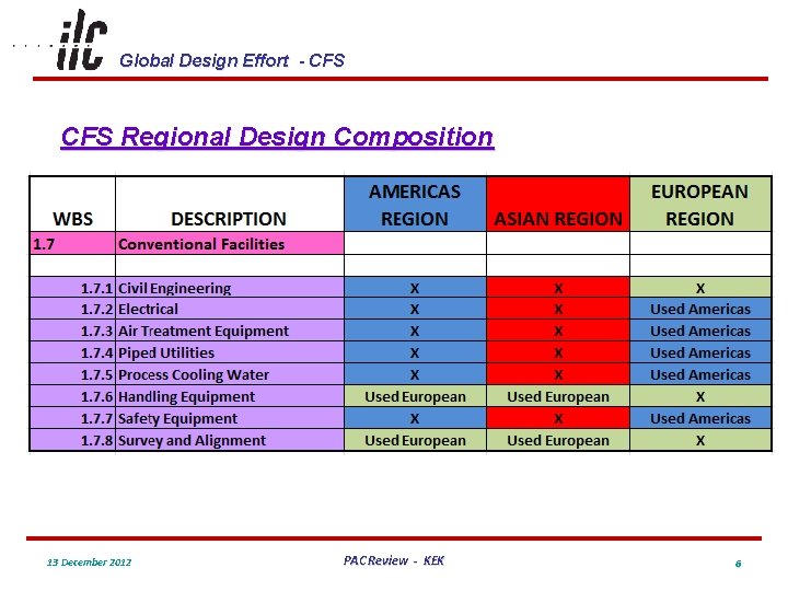
Global Design Effort - CFS Regional Design Composition 13 December 2012 PAC Review - KEK 6
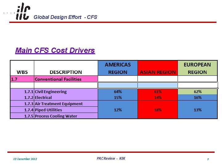
Global Design Effort - CFS Main CFS Cost Drivers 13 December 2012 PAC Review - KEK 7
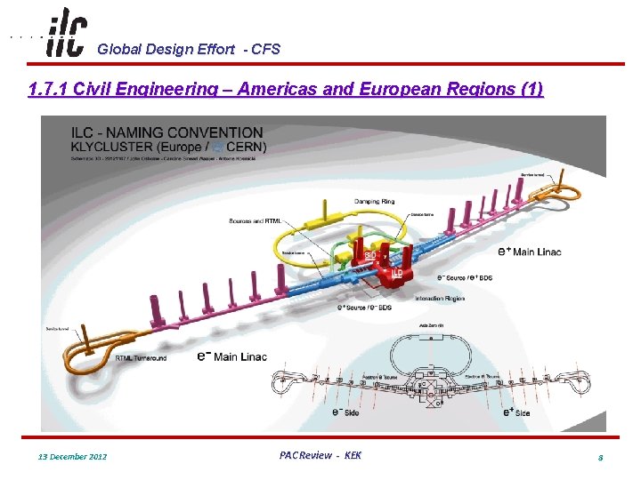
Global Design Effort - CFS 1. 7. 1 Civil Engineering – Americas and European Regions (1) 13 December 2012 PAC Review - KEK 8
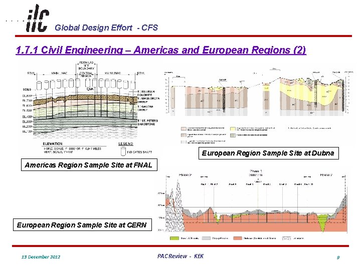
Global Design Effort - CFS 1. 7. 1 Civil Engineering – Americas and European Regions (2) European Region Sample Site at Dubna Americas Region Sample Site at FNAL European Region Sample Site at CERN 13 December 2012 PAC Review - KEK 9
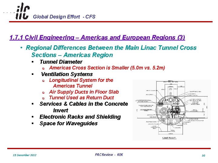
Global Design Effort - CFS 1. 7. 1 Civil Engineering – Americas and European Regions (3) • Regional Differences Between the Main Linac Tunnel Cross Sections – Americas Region § Tunnel Diameter q § Americas Cross Section is Smaller (5. 0 m vs. 5. 2 m) Ventilation Systems q q q Longitudinal System for the Americas Tunnel Air Supply Ducts in Floor Slab Tunnel Used as Return Duct § Services & Cables in the Concrete Invert § Electronic Racks and Shielding § Space for Waveguides 13 December 2012 PAC Review - KEK 10
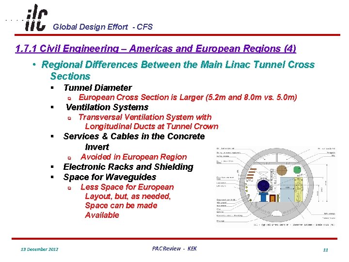
Global Design Effort - CFS 1. 7. 1 Civil Engineering – Americas and European Regions (4) • Regional Differences Between the Main Linac Tunnel Cross Sections § Tunnel Diameter q § European Cross Section is Larger (5. 2 m and 8. 0 m vs. 5. 0 m) Ventilation Systems q Transversal Ventilation System with Longitudinal Ducts at Tunnel Crown § Services & Cables in the Concrete Invert q Avoided in European Region § Electronic Racks and Shielding § Space for Waveguides q 13 December 2012 Less Space for European Layout, but, as needed, Space can be made Available PAC Review - KEK 11
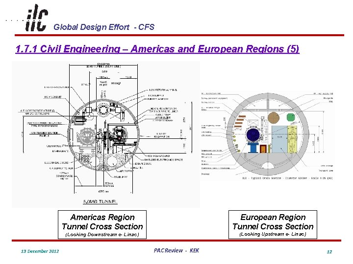
Global Design Effort - CFS 1. 7. 1 Civil Engineering – Americas and European Regions (5) 13 December 2012 Americas Region Tunnel Cross Section European Region Tunnel Cross Section (Looking Downstream e- Linac) (Looking Upstream e- Linac) PAC Review - KEK 12
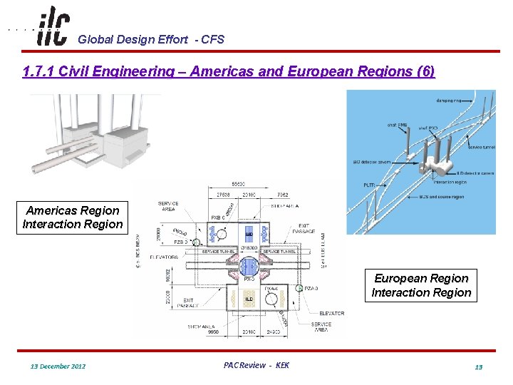
Global Design Effort - CFS 1. 7. 1 Civil Engineering – Americas and European Regions (6) Americas Region Interaction Region European Region Interaction Region 13 December 2012 PAC Review - KEK 13
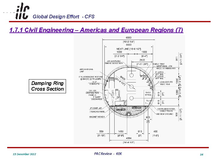
Global Design Effort - CFS 1. 7. 1 Civil Engineering – Americas and European Regions (7) Damping Ring Cross Section 13 December 2012 PAC Review - KEK 14
Global Design Effort - CFS 1. 7. 1 Civil Engineering – Americas and European Regions (8) • Tunnel Lengths for Both Regions are the Same Based on the Same Machine Lattice • The Americas Region Used the Same Diameter TBM for Main Tunnel Drives and Drill and Blast Methods to Enlarge Enclosure Areas as Needed • The European Region Uses a Larger Diameter TBM where Technical Equipment Requires a Larger Dimensional Space • All Service Tunnels for Both Regions Use a Uniform Diameter TBM 13 December 2012 PAC Review - KEK 15
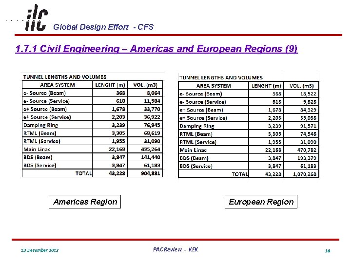
Global Design Effort - CFS 1. 7. 1 Civil Engineering – Americas and European Regions (9) Americas Region 13 December 2012 European Region PAC Review - KEK 16
Global Design Effort - CFS 1. 7. 1 Civil Engineering – Americas and European Regions (10) Americas Region European Region § Areas of Refuge are Provided § All Non-TBM Construction is Considered a Cavern § Fire-Protected Connections are Required for Shaft Access § Volumes for Sources are Mostly Considered BDS § Americas Interaction Region has a Larger Footprint § Shaft Construction Extends to Tunnel Floor Level § Shaft Base Caverns do not Include Shaft Volumes § Areas of Refuge are Not Needed § Some Minor Tunnel Widening is not Considered a Cavern § Protected Shaft Access is not Required § Volumes for Sources are Considered as a % of Total § European Interaction Region is More Compact § Shaft Construction Extends to Top of Base Cavern § Shaft Base Caverns does Include Shaft continuation Volumes 13 December 2012 PAC Review - KEK 17
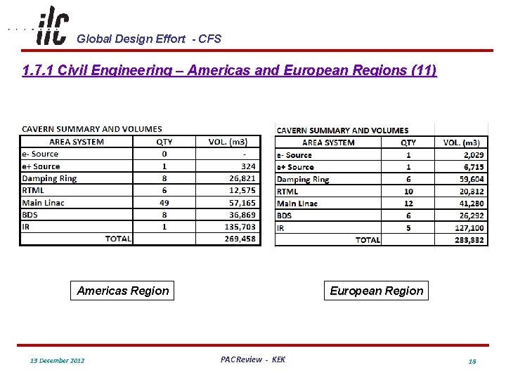
Global Design Effort - CFS 1. 7. 1 Civil Engineering – Americas and European Regions (11) Americas Region 13 December 2012 European Region PAC Review - KEK 18
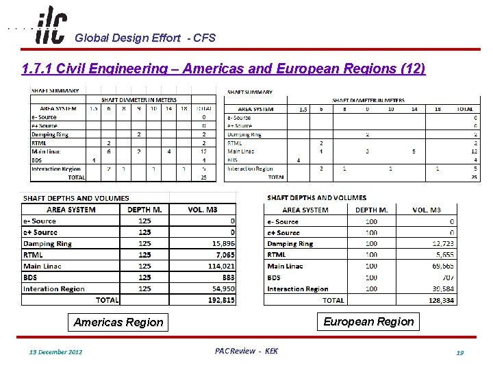
Global Design Effort - CFS 1. 7. 1 Civil Engineering – Americas and European Regions (12) European Region Americas Region 13 December 2012 PAC Review - KEK 19
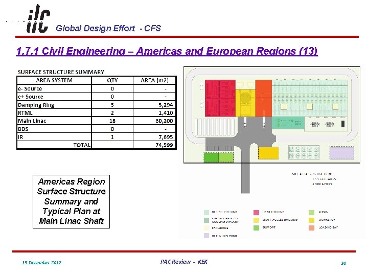
Global Design Effort - CFS 1. 7. 1 Civil Engineering – Americas and European Regions (13) Americas Region Surface Structure Summary and Typical Plan at Main Linac Shaft 13 December 2012 PAC Review - KEK 20
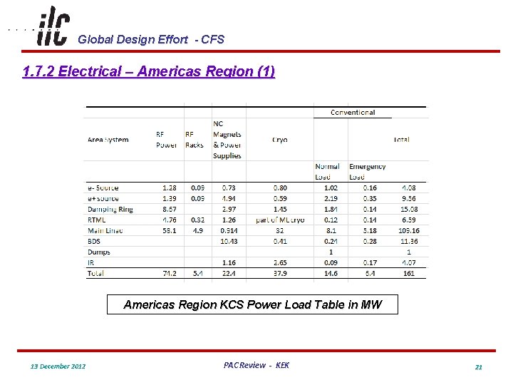
Global Design Effort - CFS 1. 7. 2 Electrical – Americas Region (1) Americas Region KCS Power Load Table in MW 13 December 2012 PAC Review - KEK 21
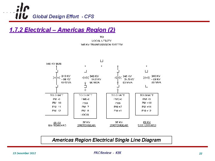
Global Design Effort - CFS 1. 7. 2 Electrical – Americas Region (2) Americas Region Electrical Single Line Diagram 13 December 2012 PAC Review - KEK 22
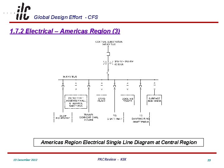
Global Design Effort - CFS 1. 7. 2 Electrical – Americas Region (3) Americas Region Electrical Single Line Diagram at Central Region 13 December 2012 PAC Review - KEK 23
Global Design Effort - CFS 1. 7. 3 Air Treatment – Americas Region (1) • Two Separate Ducted Air Supply Systems Provide Conditioned Air to the Tunnel Enclosures § General Supply Air with 20% Fresh Air § Emergency Supply Air to Areas of Refuge (AOR) When Needed • The Tunnel Enclosure Serves as the Air Return to Ducted Returns at Each Shaft • Conditioned Supply Air will Maintain Tunnel Air Temperatures at 86 o. F (30 o. C) – Temperature Stability +/- 1 o. C • Damping Ring and BDS have Additional Fan Coil Units to Maintain Tunnel Temperature Due to Addition Heat Loading and Stricter Temperature Tolerances +/- 0. 1 o. C 13 December 2012 PAC Review - KEK 24
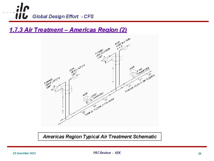
Global Design Effort - CFS 1. 7. 3 Air Treatment – Americas Region (2) Americas Region Typical Air Treatment Schematic 13 December 2012 PAC Review - KEK 25
Global Design Effort - CFS 1. 7. 4 Piped Utilities – Americas Region (1) • Tunnel and Enclosure Groundwater Inflow and Condensate Drainage Estimated as 21 m 3/h/km • Duplex Sumps Discharged Through Shafts § § § 132 in Main Linac 121 in Central Region and IR 32 in Damping Ring • Surface Holding Tanks will Provide Monitoring Capability Prior to Discharge • Sprinkler Systems Throughout Underground Enclosures and Surface Buildings • Domestic Water and Sanitary Facilities Typically at the Base of Shafts and in Surface Buildings 13 December 2012 PAC Review - KEK 26
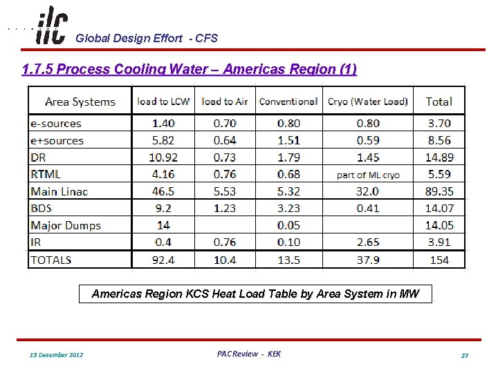
Global Design Effort - CFS 1. 7. 5 Process Cooling Water – Americas Region (1) Americas Region KCS Heat Load Table by Area System in MW 13 December 2012 PAC Review - KEK 27
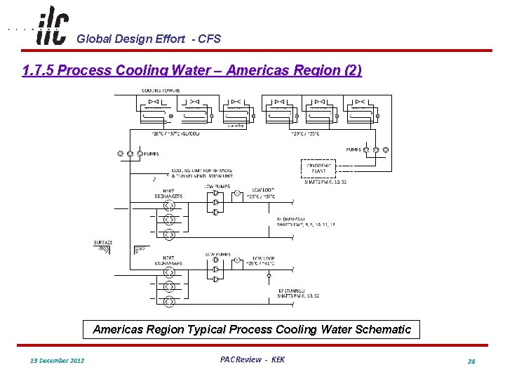
Global Design Effort - CFS 1. 7. 5 Process Cooling Water – Americas Region (2) Americas Region Typical Process Cooling Water Schematic 13 December 2012 PAC Review - KEK 28
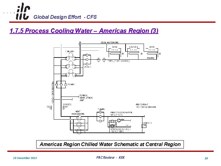
Global Design Effort - CFS 1. 7. 5 Process Cooling Water – Americas Region (3) Americas Region Chilled Water Schematic at Central Region 13 December 2012 PAC Review - KEK 29
Global Design Effort - CFS 1. 7. 7 Safety Equipment – Americas Region (1) • Based on Requirements in National Fire Protection Association (NFPA) Standard for Subterranean Spaces, 2005 Edition • Verified Single Main Linac Tunnel Solution • Supported by Two Studies Conducted by Hughes Associates, Inc. § § Code Analysis and Recommendations Single Tunnel Analysis Using Fire Dynamics Simulator (FDS) which is a Computational Fluid Dynamics Program Developed by the USA National Institute of Standards • Personnel Egress § § § Hazardous Equipment and Shaft Elevators Protected by 2 hr. Fire Rated Walls and Doors Main Linac Tunnel Serves as Escape Route Emergency Lighting, Illuminated Exit Signage and Directional Signs • Automatic Sprinkler Protection • Addressable Fire Detection System 13 December 2012 PAC Review - KEK 30
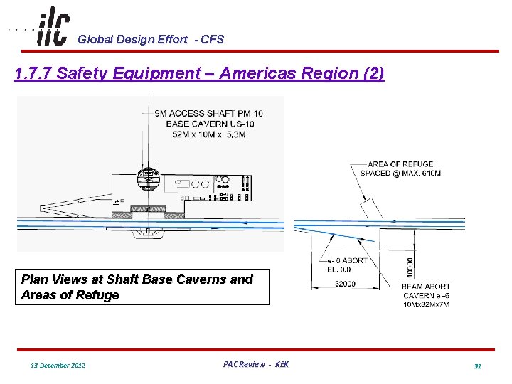
Global Design Effort - CFS 1. 7. 7 Safety Equipment – Americas Region (2) Plan Views at Shaft Base Caverns and Areas of Refuge 13 December 2012 PAC Review - KEK 31
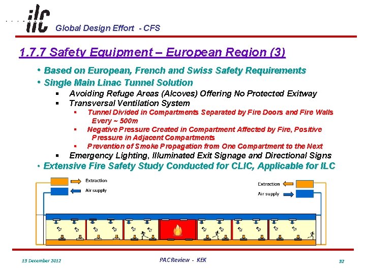
Global Design Effort - CFS 1. 7. 7 Safety Equipment – European Region (3) • Based on European, French and Swiss Safety Requirements • Single Main Linac Tunnel Solution § § Avoiding Refuge Areas (Alcoves) Offering No Protected Exitway Transversal Ventilation System § § Tunnel Divided in Compartments Separated by Fire Doors and Fire Walls Every ~ 500 m Negative Pressure Created in Compartment Affected by Fire, Positive Pressure in Adjacent Compartments Prevention of Smoke Propagation from One Compartment to the Next Emergency Lighting, Illuminated Exit Signage and Directional Signs • Extensive Fire Safety Study Conducted for CLIC, Applicable for ILC 13 December 2012 PAC Review - KEK 32
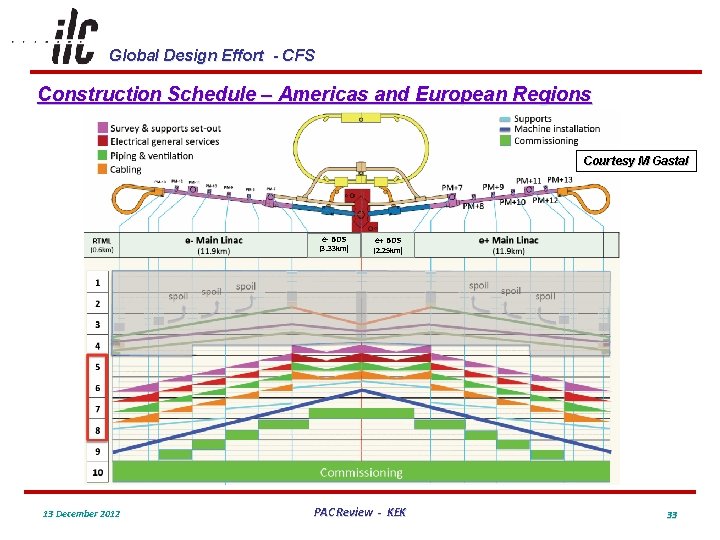
Global Design Effort - CFS Construction Schedule – Americas and European Regions Courtesy M Gastal e- BDS (3. 33 km) 13 December 2012 e+ BDS (2. 25 km) PAC Review - KEK 33
Global Design Effort - CFS Summary • Regional Conditions have had a Large Impact on the ILC Conventional Facilities Design • In Both the Americas and European Regions Civil Design was Primarily Completed by In-House CFS Personnel Supported by Outside A/E Consultants • In the Americas Region a Complete Mechanical and Electrical Design was Completed by Outside A/E Consultants Supported by CFS In-House Personnel • Compared to the RDR the Overall Design Maturity has Greatly Improved in All Regions 13 December 2012 PAC Review - KEK 34
- Slides: 34