GLAST LAT Project Gammaray Large Area Space Telescope


- Slides: 23

GLAST LAT Project Gamma-ray Large Area Space Telescope MRB NCR 562 Bay 0 and 4 TPS Removal and Replacement LAT Integration and Test and Systems Engineering August 25, 2005 1

GLAST LAT Project Recommendation Option 3: TPS Removal • Allows repair of TPS • Minimizes risk of damage to Flight Hardware • ELX has recalibration method for TEM/TPS telemetry • Accurate shim determination requires TPS or TPS/TEM/CAL measurement • TPS height and flatness data will be used to determine offset • TPS selection determined by best fit for shim, then ELX criteria • TEM or TEM/CAL could be removed if TPS data fails to meet criteria August 25, 2005 2

GLAST LAT Project Options 1 through 5 are discussed in subsequent charts: Option 1: Use As Is Option 2: TPS Removal and Rework Option 3: TPS Removal Option 4: TEM/TPS Removal Option 5: CAL/TEM/TPS Removal August 25, 2005 3

GLAST LAT Project Option 1 – Use-As-Is • • I&T Mechanical Pros: – No demate of flight connections – No change to accurately measured CAL/TEM/TPS stack height I&T Mechanical Cons: – None I&T Electrical Pros: – No additional testing required I&T Electrical Cons: – None ELX Pros: – No immediate change to TEM/TPS calibration or performance ELX Cons: – Power supply circuit design is marginally stable with temperature – 2 different TPS configurations within the LAT Potential Risks: – Power supply oscillation could negatively impact detector performance – Power supply oscillation could worsen over temperature and time – Rework later in the program could increase risk. Discussion: – ELX and SE have recommended against selecting this option. August 25, 2005 4

GLAST LAT Project Option 2 – TPS Removal and Rework • • I&T Mechanical Pros: – Demate TPS/TEM connection in Grid – Low Risk – Demate TPS/PDU connection in Grid – Low Risk, but connector jack screw may loosen – Maintains CAL/TEM/TPS stack height I&T Mechanical Cons: – None I&T Electrical Pros: – Maintains TEM/TPS telemetry calibration – Maintains calibration of Tracker and Calorimeter detectors I&T Electrical Cons: – Need regression test definition to validate re-assembled TEM/TPS in the grid ELX Pros: – Permits rework of TPS for power supply oscillation – Maintains TEM/TPS telemetry accuracy – Maintains TEM/TPS Performance ELX Cons: – Testing of removed TPS required Potential Risks: – Impact to I&T schedule while TPS is reworked and retested August 25, 2005 5

GLAST LAT Project Option 3 – TPS Removal • • • I&T Mechanical Pros: – Good access to the interface between TEM and TPS – Shimming may not be required if TPS box height meets criteria – Demate TPS/TEM connection in Grid – Low Risk – Demate TPS/PDU connection in Grid – Low Risk, but connector jack screw may loosen I&T Mechanical Cons: – Stack height measurement is invalidated and becomes inferred – If shimming is required it is a more complex operation to loosen and shim at the CAL interface I&T Electrical Pros: – None I&T Electrical Cons: – Requires recalibration of TEM/TPS telemetry – Need regression test definition to validate new TEM/TPS Assembly in the grid • Requires recalibration of Tracker and Calorimeter detectors ELX Pros: – Permits rework of TPS for power supply oscillation ELX Cons: – Degradation in TEM/TPS telemetry accuracy – TEM/TPS measured performance becomes inferred August 25, 2005 6

GLAST LAT Project Option 3 – TPS Removal (cont’d) • • Potential Risks: – Unknown where or how shimming will be performed, if required – Shimming in the Grid has not been demonstrated. Discussion: – 18 TPS units have measured flatness variation within 1 mil – 17 TPS units have measured height variation within 4 mils – Height was not measured for TPS units currently installed in Bays 0 [GLAT 1749 sn 22] and 4 [GLAT 1750 sn 03] – GLAT 1749 and GLAT 1750 height and flatness would be measured after removal – GLAT 1813 sn 11 and GLAT 1828 sn 02 height and flatness would be measured prior to installation – Height variance of measured TPS chassis is 0. 004 – Flatness variance of TPS measured chassis is 0. 001 August 25, 2005 7

GLAST LAT Project Option 3 – TPS Removal (cont’d) • Discussion (cont’d): – Suggested re-calibration method for new assembled units: • CAL and TKR HV Bias Currents – Maintain the slope constants for both CAL and TRK Bias currents. – Re-calibrate the intercept constants by taking current average of one thousand measurements before and after TPS replacement, and then adjust the new average measurement to old reading with new value of Intercept point. • For Total TEM/TPS current – Re-calibrate the slope and intercept constants by taking the average of one thousand measurements before and after replacement of TPS in conditions: - no TRK or CAL FE is powered - CAL FE is powered and TRK FE is not - TRK FE is powered and CAL FE is not - TRK and CAL FE is powered These four points allow make it easy to make fit and find new calibration constants for new assembly. Telemetry points can be verified by recording external PS current reading for all 4 points before and after replacement. August 25, 2005 8

GLAST LAT Project Option 3 – TPS Removal (cont’d) R&R of TPS Basic Steps: 1. Measure relative height of TEM/TPS assembly to CAL base plate in the GRID. 2. Remove TPS from TEM on CAL in GRID. 3. Measure height of TPS removed from GRID on granite table. 4. Measure new power supply on granite table. 5. Determine new shim thickness. 6. Install new shims. 7. Install new TPS. 8. Verify relative height obtained in step 1. August 25, 2005 9

GLAST LAT Project Option 3 – TPS Removal (cont’d) TPS Replacement I&T Risk Summary Risk Description Weight Factor (1 -5) Risk (1 -3) Score Demate and mate of new TPS to TEM connector. 4 2 8 If shimming is required it is a more complex operation to loosen and shim at the CAL interface* 4 3 12* Regression Testing to Validate 2 2 4 Total 24 Mitigation Plan Dry run assembly procedure Demonstrate with EM units in 1 x 4. Utilize existing single tower tests * If shimming is not required the overall risk score is reduced by 12 pts. August 25, 2005 10

GLAST LAT Project Option 4 – TEM/TPS Removal • • I&T Mechanical Pros: – Demate TPS/TEM connection outside Grid – Low Risk – Demate TPS/PDU connection in Grid – Low Risk, but connector jack screw may loosen – Exposes existing shimming interface between TEM/CAL – Shimming operation is cleaner and consistent with technique used in the metrology bay. Needs pathfinding. – Installation of thermistor cable is simplified with the box removed. I&T Mechanical Cons: – Re-shimming required • Requires new “in Grid” shimming procedure – Demate 8 TEM/TKR flex cables in Grid – Elevated Risk, EXTREMELY LOW Risk Tolerance – Demate 4 Calorimeter flex cables in Grid – Elevated Risk I&T Electrical Pros: – None I&T Electrical Cons: – Need regression test definition to validate new TEM/TPS Assembly in the grid • Requires recalibration of Tracker and Calorimeter detectors August 25, 2005 11

GLAST LAT Project Option 4 – TEM/TPS Removal (cont’d) • • • ELX Pros: – Permits rework of TPS for power supply oscillation – No degradation in TEM/TPS telemetry accuracy – TEM/TPS performance is based on measurements ELX Cons: – None Potential Risks: – Shimming in the Grid has not been demonstrated – Requires demate of TEM/TKR flex cables that could require extensive TKR rework if damaged. There are no spares. – Requires demate of TEM/CAL cables. August 25, 2005 12

GLAST LAT Project Option 4 – TEM/TPS Removal (cont’d) R&R of TEM/TPS - Basic Steps: 1. Measure relative height to CAL base plate of TEM/TPS assembly in GRID. 2. De-mate CAL, TKR, TEM to GASU, and TPS to PDU cables from TEM/PSU assembly. 3. Remove TEM/TPS from CAL in GRID. 4. Measure height of TEM/TPS removed from GRID on granite table. 5. Measure new TEM/TPS on granite table. 6. Determine new shim thickness based on the height differences between the removed and replacement assemblies. 7. Install new TEM/TPS with shim stack up determined in previous step. 8. Verify relative height obtained in step 1. 9. Install thermistor cable. 10. Mate CAL, TKR, TEM to GASU, and TPS to PDU cables to the newly installed TEM/TPS assembly August 25, 2005 13

GLAST LAT Project Option 4 – TEM/TPS Removal (cont’d) TEM/TPS Replacement I&T Risk Summary Risk Description Weight Factor (1 -5) Risk (1 -3) Score Requires breaking flight connections to CAL, TKR, GASU and PDU connections (13 Connectors). 5 3 15 Re-shimming Required 4 2 8 Demonstrate with EM units in 1 x 4. Regression Testing to Validate 2 1 2 Utilize existing single tower tests Total 25 August 25, 2005 Mitigation Plan Proceed cautiously. Do not use excessive force for mate or demate. 14

GLAST LAT Project Option 5 – CAL/TEM/TPS Removal • • I&T Mechanical Pros: – Demate TPS/TEM connection outside Grid – Low Risk – Demate TPS/PDU connection in Grid – Low Risk, but connector jack screw may loosen – Permits accurate CAL/TEM/TPS shimming in metrology bay I&T Mechanical Cons: – Demate 8 TEM/TKR flex cables in Grid – Elevated Risk, EXTREMELY LOW Risk Tolerance – Demate 4 Calorimeter flex cables outside Grid – Removal of installed shear plates for Bays 0 and 4 may not be desirable with existing nut failure (NCR 579) I&T Electrical Pros: – TEM/TPS regression testing could be performed outside of Grid – Permits TEM/CAL re-calibration in metrology bay I&T Electrical Cons: – Requires re-calibration of TKR detector in Grid ELX Pros: – Permits rework of TPS for power supply oscillation – No degradation in TEM/TPS telemetry accuracy – TEM/TPS performance is based on measurements ELX Cons: – None Potential Risks: – Requires demate of TEM/TKR flex cables which could require extensive TKR rework if damaged. There are no spares. August 25, 2005 15

GLAST LAT Project Reference • • • Completed Action Items From Previous MRB: COMPLETE - QA: identify which TPS chassis s/n are installed and to be installed. TPS/TEM ASSY TPS CHASSIS Height GLAT 1749 GLAT 1752 LAT-DS-00995 -51 -22 Not measured GLAT 1750 GLAT 1753 LAT-DS-00995 -51 -03 Not measured GLAT 1813 GLAT 1832 LAT-DS-00995 -51 -11 3. 0618 GLAT 1828 GLAT 1845 LAT-DS-00995 -51 -02 3. 0597 COMPLETE - SE: Assess impact of TPS swap based on chassis dimensions with inputs from I&T and M. Nordby. See Recommendation Only 19 of the 23 TPS chassis were measured. Flatness data variance of 19 boxes is. 001 Height data variance of 18 boxes is. 004 I&T and M. Nordby will attend MRB. COMPLETE – QA – How were TPS chassis heights measured? The measured TPS units were measured on the CMM (Coordinate Measurement Machine). The height measurement of 3. 060 ± 0. 005 was measured by the CMM's gaussian best fit plane. The part was constrained to the granite table per drawing instructions for parallelism. The TPS units were measured for a 0. 010" parallelism free state condition, there were a few close to the limit, but not out of tolerance. The parallelism measurement was performed with an indicator and height gage. COMPLETE (See presentation) - I&T: assess feasibility of performing height measurements in Grid for all options. COMPLETE (See presentation) - I&T: assess shimming in Grid shimming for all options. COMPLETE - ELX: identify candidate TPS for installation in to Bays 0 and 4 Suggestion is to use for TPS replacement on tower A and B the following units: 1. GLAT 1813 TPS from Assembly GLAT 1832 should replace TPS GLAT 1749 from assembly GLAT 1752 2. GLAT 1828 TPS from Assembly GLAT 1845 should replace TPS GLAT 1750 from assembly GLAT 1753. August 25, 2005 16

GLAST LAT Project Reference • • COMPLETE - ELX: identify candidate TPS for installation in to Bays 0 and 4 Suggestion is to use for TPS replacement on tower A and B the following units: – 1. GLAT 1813 TPS from Assembly GLAT 1832 should replace TPS GLAT 1749 from assembly GLAT 1752 – 2. GLAT 1828 TPS from Assembly GLAT 1845 should replace TPS GLAT 1750 from assembly GLAT 1753. Selection of these units are based on similarity of HV calibration constants August 25, 2005 17

GLAST LAT Project Reference • Bay 0 GLAT 1813 -> GLAT 1749 1752 (TPS GLAT 1749) Calibration CAL Bias Current TKR Bias Current Date Slope Intercept 2/2/05 0. 930382662178 -0. 0014032780581 2/2/05 0. 935558213381 0. 00234355041672 2/2/05 66. 973583 -1. 518328 TEM/TPS Current • 1832 (TPS GLAT 1813) Calibration CAL Bias Current TKR Bias Current Date Slope Intercept 5/9/05 0. 917697111398 0. 000884641517652 5/9/05 0. 937436903933 0. 0211388061165 5/9/05 66. 993715 -0. 837730 TEM/TPS Current August 25, 2005 18

GLAST LAT Project Reference • Bay 4 GLAT 1828 -> GLAT 1750 Date Slope • Calibration 1753 (TPS GLAT 1750) CAL Bias Current TKR Bias Current Intercept 1/31/05 1. 05784628111 0. 00439458111717 1/31/05 0. 930910460477 -0. 0122075240151 1/31/05 66. 510847 0. 064750 TEM/TPS Current • 1845 (TPS GLAT 1828) Calibration CAL Bias Current TKR Bias Current Date Slope Intercept 5/9/05 1. 00367085354 -0. 00551484961688 5/9/05 0. 956402741661 0. 00380408724678 5/9/05 66. 388597 0. 089839 TEM/TPS Current August 25, 2005 19

GLAST LAT Project Reference • • • August 25, 2005 NCR 562 - TPS CCAs on GLAT 1752 and GLAT 1753 TEM/TPS assys have not been reworked per NCR #397 to correct observed oscillation of CAL 3. 3 V digital. Assemblies were integrated onto the Grid before the problem was observed in TEM/TPS test data From Parent NCR 397 Description of Non Conformance Oscillation of CAL-3. 3 V Digital when TEM/TPS tester board is connected. Amplitude was found around 100 m. V, 1 -2 KHz frequency. Oscillation is triggered at power-on of calorimeter and sustained. No oscillation is present when turning the power on at cold temperatures (-40 C). At room-temperature oscillation might or might not be triggered by power-on. At hot temperatures (+50 C) oscillation was always triggered at power-on. Whether or not the oscillation is triggered at power-up, is dependant of the temperature at power-up. If the temperature of the module is changed after power up, the presence of oscillation (or not) is maintained and is independent of whether the temperature is changed. Test showed that the supply only oscillates with loads drawing around/more than 1. 2 A. It does not oscillate at loads of around 600 m. A (the CAL has <1 A). In addition it appears to only oscillate when capacitive loads are added in parallel to the resistive loads. No oscillation was observed at the TPS-only test. That tester includes tests at 150% of the cal nominal load, but does not have capacitive loads in parallel. It is not clear whether the problem is present when CAL AFEE boards are connected. It is known that on tower A and B the TPS system is stable at room-temperature. Dispositions: (Cullinan, 4/5/05) Per MRB discussion 4/1/05 and 4/4/05, the following rework on the qual TPS board is underway on AIDS #974 to resolve the oscillation issue observed: 1. Conformal coating on board in areas adjacent to CAL resistors R 53, R 58, TKR resistors R 122, R 142, R 61, TEM resistor R 20, R 50 has been removed using wooden stick in preparation for attaching capacitors to be connected in parallel with these resistors, per direction from G. Haller. Caps will use 30 gauge wire pigtails to connect to on board resistors. Caps CDR 33 BX 473 AKUS will be used in this application. Caps will be bonded to board using Hysol EA 9394. 20

GLAST LAT Project Reference • • • August 25, 2005 NCR 562 – (cont’d) 2. On board CAL resistors R 28, R 25, R 51, R 52 will be removed and replaced with 2. 74 KOhm resistors M 55342 K 06 B 2 E 74 R per G. Haller direction. 3. On board Compensation Capacitors C 531, C 532 (CAL bias) and C 631, C 632, C 633 (TKR bias) have present value of 10 p. F. Remove and replace these caps with 100 p. F caps (on TPS CCA parts list), P/N CDR 31 BP 101 BKUS. Dispo #2 (Cullinan, 4/7/05) Rework was completed 4/6/05 and the qual TPS board was tested on the TPS tester and connected to the AFEE/MCMs and tested up to 75 deg. C. Per G. Haller, oscillation was not observed with simulated load of greater than 150% of expected TKR load. Oscillations were noted on high voltage when simulated load was approx. 250% of expected TKR load. MRB was held 4/7/05. In attendance were Haller, Sapozhnikov, Hascall, Bright, Klaisner, Cullinan, Bloom, J. Lohr, B. Graf, N. Johnson to discuss test results. MRB concurred that testing performed to date was sufficient to validate new qual TPS board configuration and the elimination of the oscillation within TPS performance requirements. Additional TPS board testing will be completed 4/7/05. All testing will be performed to AIDS #974, with data packages attached to this AIDS. Qual TPS board will be reinstalled into TPS base. Thermal compound CV-2946 will not be used (SLAC does not have material on hand) between board and TPS base. Analysis by DAQ showed temperature rise of TPS board was approximately 3 -4 deg C without thermal compound. Also, areas where conformal coating was removed and newly added pigtailed capacitors will not be covered with Arathane conformal coating at this time. In addition, all screws securing the TPS board into the TPS base, securing the TPS lid, and securing the TPS to the TEM will not be staked with Hysol 0151. These materials are not immediately available at SLAC. Need for qual TEM/TPS for testing at NRL is urgent and the qual TPS board can be used for NRL testing in this configuration. When Qual TEM/TPS is returned to SLAC, the TPS will be reassembled to include these materials to return the unit to meet the assembly drawing. MRB also discussed the plan to document these configuration changes. Relevant TPS assembly drawings, schematics and BOMs will need to be revised. Report list of documents that will be revised to this NCR once list is compiled. 21

GLAST LAT Project Reference • • • August 25, 2005 NCR 562 – (cont’d) MRB also concurred to rework remaining TPS boards at SLAC prior to pre-conformal coat performance testing and thermal cycle testing. The CCAs will arrive from General Technology and will be reworked per this NCR and AIDS #994. The redlined schematic used to document configuration changes for the qual TPS CCA will be used for reworking the other TPS boards. The TPS CCA schematic diagram, assembly drawing and BOM/parts list will be revised to capture redline changes. GSFC inspection of reworked CCAs will be performed by Tracy Shepherd. Following rework, TPS CCAs will complete performance and thermal cycle testing and returned to General Technology for final assembly. Dispo #3 (Cullinan, 4/12/05) Rework (including capacitor/jumper wire staking with EA 9394), inspection and Performance testing has been completed on TPS CCAs GT 104, 105, 106, 108, 109, 110. GT 104, 105, 106 and 108 to be shipped to GT; GT 109, 110 still require performance and thermal cycle testing following rework. Photographs of individually staked capacitors/jumper wires and overall board views were taken for all boards and are stored on V drive under Ancillary file in Electronics folder (under GLAST folder on V drive). All remaining boards received from GT will be reworked per this NCR and AIDS #994. Dispo #4 (cullinan, 4/20/05) TPS boards GT 109 and GT 110 successfully completed EICIT (LAT-TD 04850 -1), SVT (LAT-TD-04849 -1), performance testing (LAT-TD-01652 -4), thermal cycling (5 cycles) and post thermal cycle performance testing (LAT-TD-01652 -4) on AIDS #872 following rework. All test results have been retained in the work order binders generated for each CCA and archived in bonded stores. The following drawings have been revised to document this TPS CCA rework and are currently in sign off cycle: 1. TPS CCA assembly LAT-DS-02388, update to rev. 58 2. TPS CCA Schematic, LAT-DS-02390, updated to rev. 57 3. TPS CCA BOM, LAT-DS-02391, updated to rev. 57 Per MRB 4/14/05, DAQ Electronics group to provide an advisory memo to Systems Engineering documenting this anomaly and directing test and service operations of the TEM/TPS to avoid any condition that would risk initiating oscillation. 22

GLAST LAT Project Reference • • August 25, 2005 NCR 562 – (cont’d) MRB concluded that no additional EMI/EMC testing or workmanship vibration testing is required for the reworked qual TEM/TPS module. Plan is to close this NCR with MRB approval, and open new NCR to document required rework for TPS CCAs currently installed in TPS boxes of GLAT 1752 and GLAT 1753 flight modules currently integrated onto Towers 1 and 2. Plan is to remove these TPS boxes and rework/replace with reworked TPS CCAs. (Cullinan, 7 -14 -05) NCR #562 created per MRB to direct disposition of GLAT 1752 and GLAT 1753 TEM/TPS for reworking the TPS CCAs of these two assemblies. 23
 Epo ops
 Rubra fusca flava alba
 High definition space telescope
 James nasa says space launch its
 Mri heat
 James webb space telescope
 Raytheon james webb space telescope
 James webb nasa space telescope launch
 Fermi space telescope
 How large is space
 How large is space
 How large is space
 Curreor
 Długość pewnej linii kolejowej to około 384 km
 Lat dorsi action
 Równanie oznaczone
 Polat tarkibi
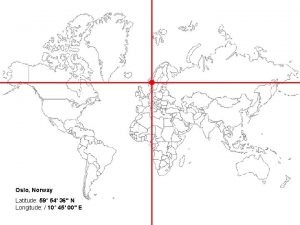
 Oslo norway latitude
 Muscles of thoracic spine
 Lat prayers
 Urgermanska språkhistoria
 Sao paulo latitude and longitude
 Situationsbaserat ledarskap
 Zanjirga ulangan katta po'lat ilgak


