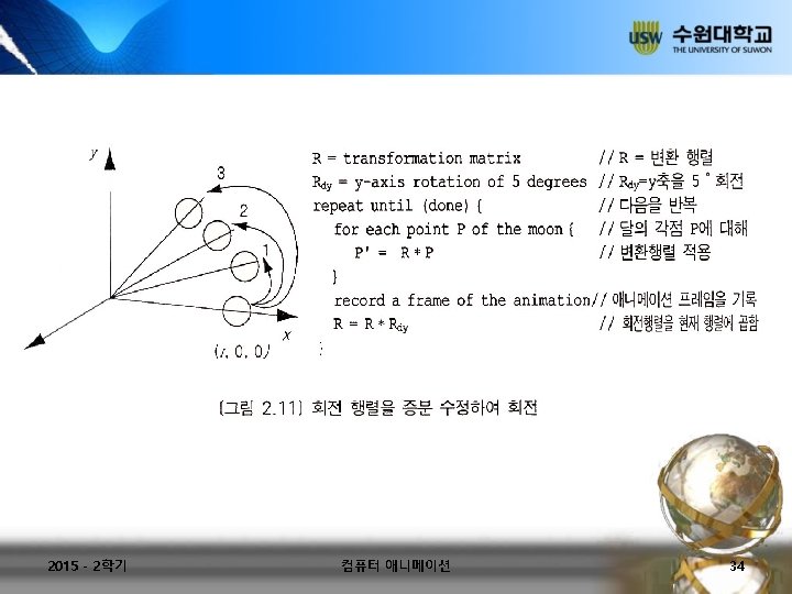
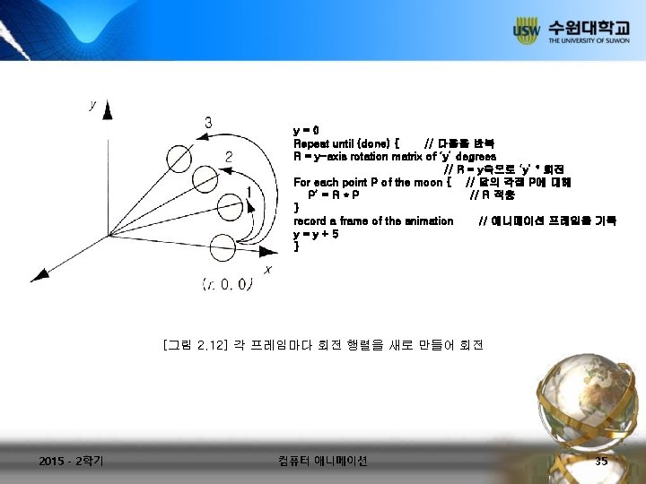
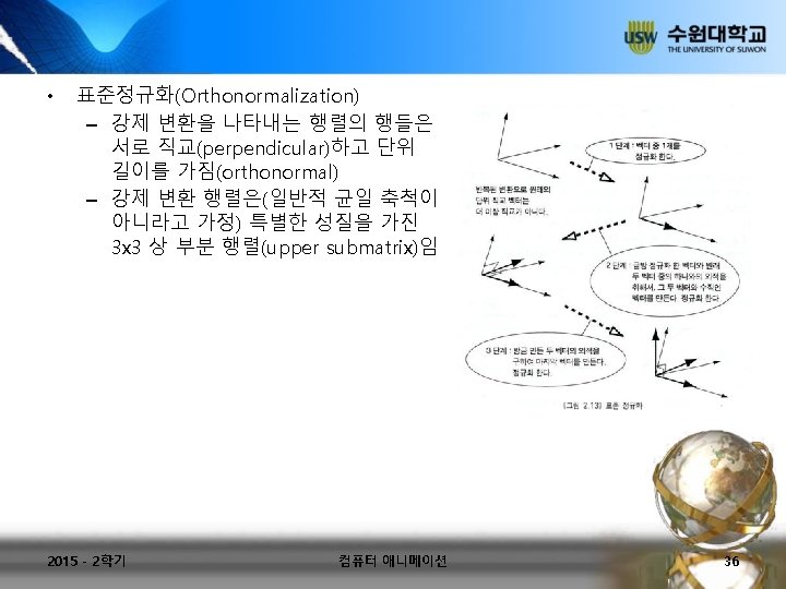
Gimbal lock From Wikipedia the free encyclopedia Gimbal


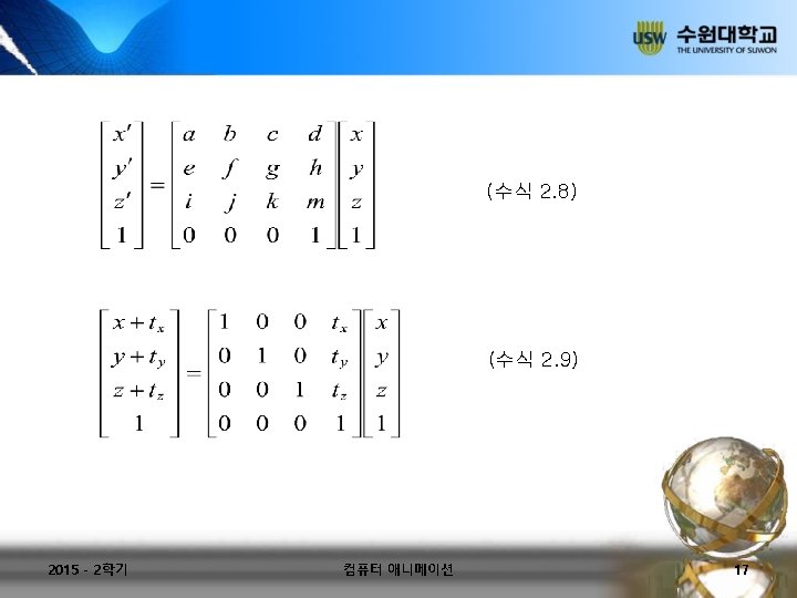

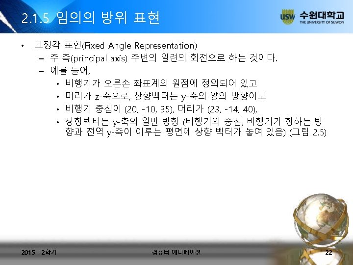
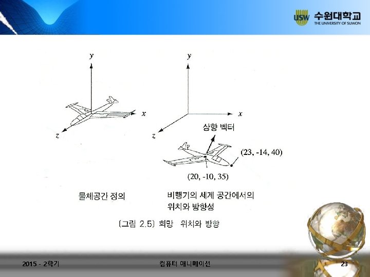
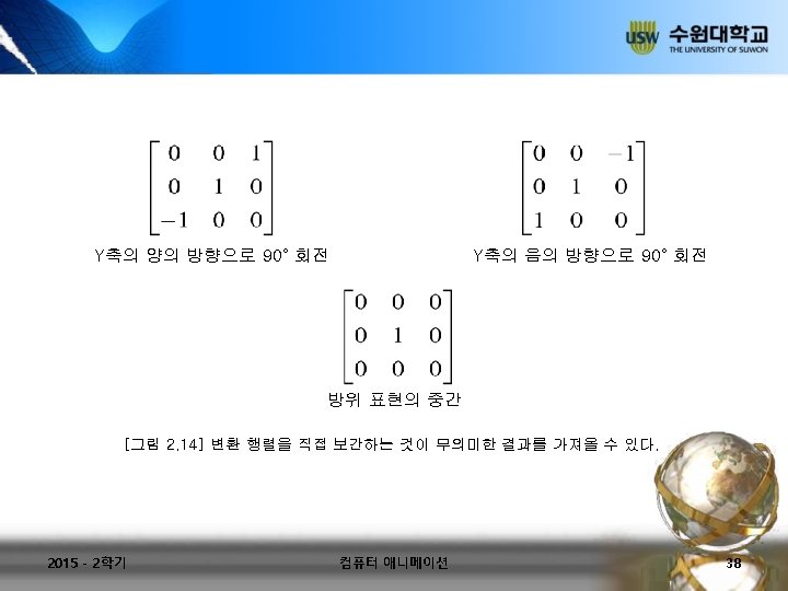

Gimbal lock • From Wikipedia, the free encyclopedia • Gimbal lock occurs when the axes of two of the three gimbals needed to compensate for rotations in three dimensional space are driven to the same direction. • For example, assume a sensing platform on an aircraft flying due north has its three gimbal axes mutually at right angles, i. e. , Pitch, Roll and Yaw angles each zero. If the aircraft pitches up 90 degrees, the Pitch and Roll axes become parallel, and changes about Yaw can no longer be compensated for. This problem may be overcome by use of a fourth gimbal, driven so as to maintain a large angle between Pitch and Yaw gimbal axes. • A comparison is to the use of Azimuth angles (Rotation clockwise from North) to define direction. At the poles (latitude 90° north or south), Azimuth becomes meaningless because the poles are singularity points, where all directions in terms of Azimuth are South (or North). 2015 - 2학기 컴퓨터 애니메이션 41

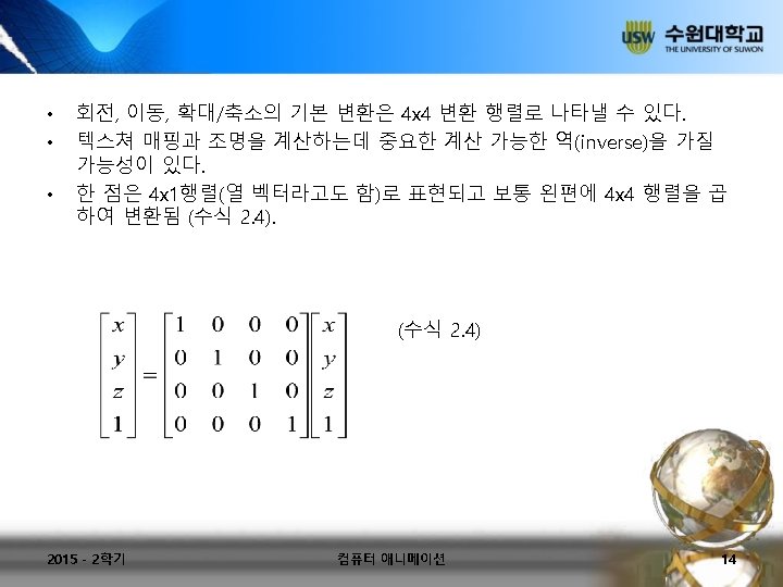
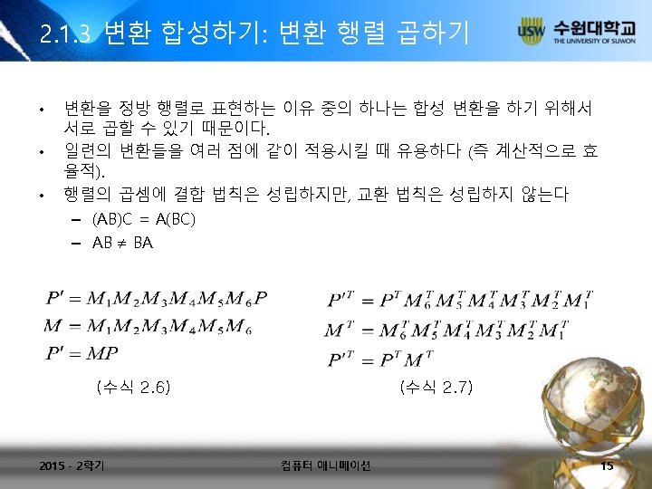
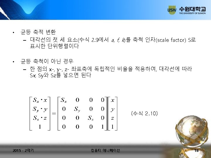
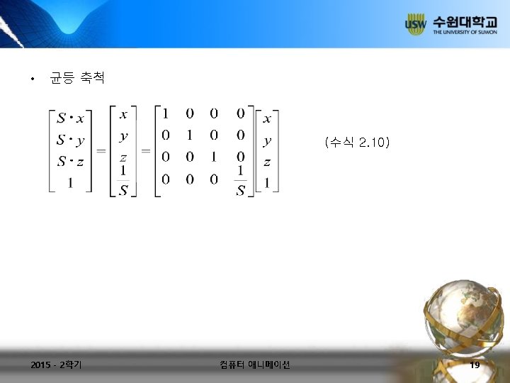
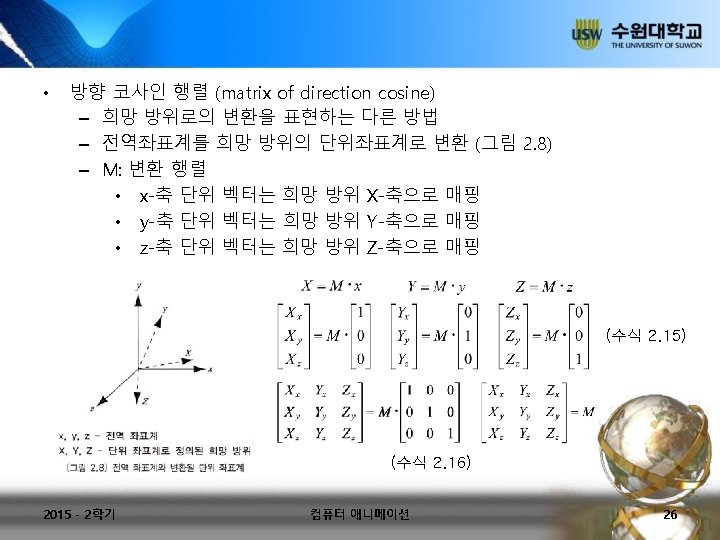
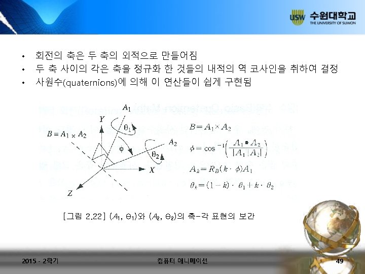
Gimbal • A gimbal is a pivoted support that allows the rotation of an object about a single axis. A set of two gimbals, one mounted on the other with pivot axes orthogonal, may be used to allow an object mounted on the innermost gimbal to remain vertical regardless of the motion of its support. For example, shipboard compasses, stoves and even drink holders typically use gimbals to keep them upright with respect to the horizon despite the ship's pitching and rolling. • Illustration of a simple two-axis gimbal set. In inertial navigation, as applied to ships and submarines, a minimum of three gimbals is needed to allow an Inertial Navigation System platform (stable) to remain fixed in inertial space, compensating for the ship's Yaw (direction) as well as its Pitch and Roll. In this application, the Inertial Measurement Unit is equipped with three orthogonally mounted gyros to sense rotation about all axes in three dimensional space. The gyro outputs drive motors controlling the orientation of the three gimbals as required to maintain the orientation of the IMU. In turn, angular measurement devices, called "resolvers" mounted on the three gimbals provide the nine cosine values for the direction cosine matrix needed to orient the ship. 2015 - 2학기 컴퓨터 애니메이션 42

• In aerospace inertial navigation systems, Gimbal lock may occur when vehicle rotation causes two of the three gimbal rings to align with their pivot axes in a single plane. When this occurs, it is no longer possible to maintain the sensing platform's orientation. To avoid this problem, a fourth gimbal must be employed, driven so as to keep the other three at substantial angles to each other. Modern practice is to avoid the use of gimbals entirely by mounting the inertial sensors directly to the body of the vehicle strapdown system and integrating sensed rotation and acceleration digitally using Quaternion methods to derive vehicle orientation and velocity. • In spacecraft propulsion, rocket engines are generally mounted on a pair of gimbals to allow a single engine to vector thrust about both Pitch and Yaw. To control Roll, twin engines with differential Pitch or Yaw control signals are used to provide torque about the vehicle's Roll axis. 2015 - 2학기 컴퓨터 애니메이션 43

- Slides: 53