
Gigabit Ethernet Group 1 Harsh Sopory Kaushik Narayanan
Gigabit Ethernet Group 1 Harsh Sopory Kaushik Narayanan Nafeez Bin Taher
Background Information An introduction to Gigabit Ethernet
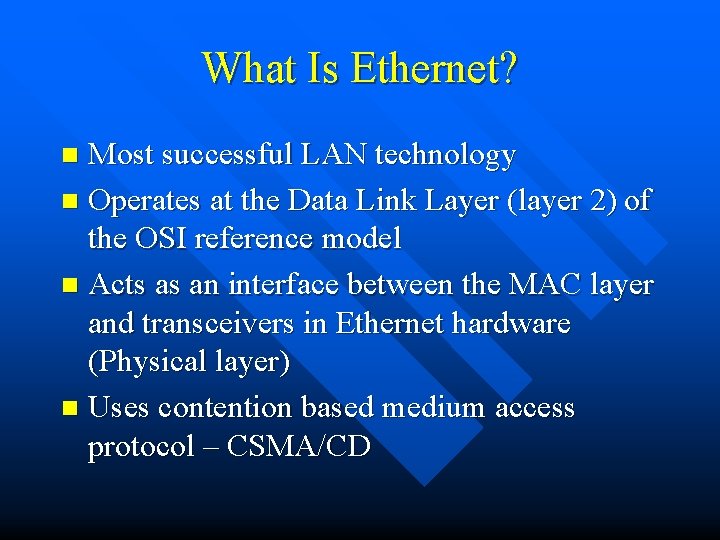
What Is Ethernet? Most successful LAN technology n Operates at the Data Link Layer (layer 2) of the OSI reference model n Acts as an interface between the MAC layer and transceivers in Ethernet hardware (Physical layer) n Uses contention based medium access protocol – CSMA/CD n
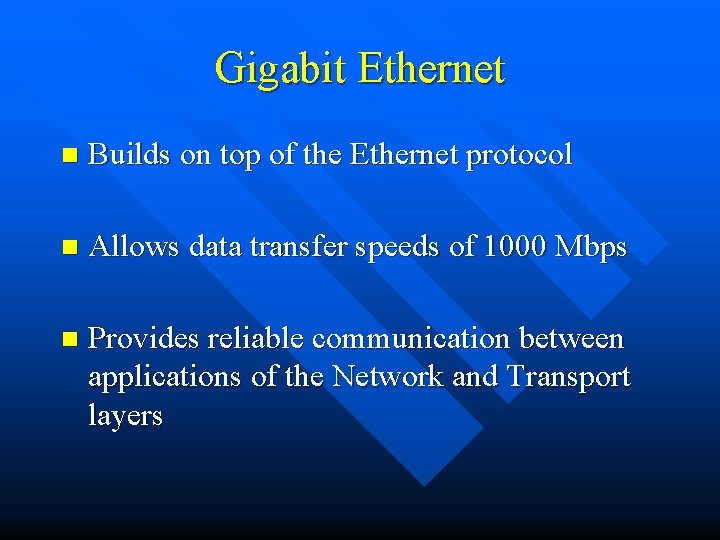
Gigabit Ethernet n Builds on top of the Ethernet protocol n Allows data transfer speeds of 1000 Mbps n Provides reliable communication between applications of the Network and Transport layers
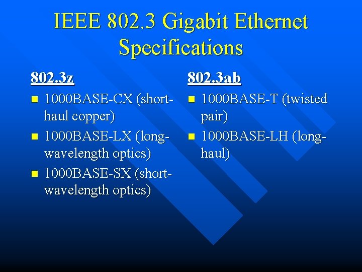
IEEE 802. 3 Gigabit Ethernet Specifications 802. 3 z n n n 1000 BASE-CX (shorthaul copper) 1000 BASE-LX (longwavelength optics) 1000 BASE-SX (shortwavelength optics) 802. 3 ab n n 1000 BASE-T (twisted pair) 1000 BASE-LH (longhaul)
Benefits of Gigabit Ethernet n Higher data transfer rates n Builds on current Ethernet n Familiar technology n Minimal staff training

Project Proposal Our aim and immediate goals
Project Aim n Main Issue: High costs associated with installing Gigabit Ethernet technology n A source of high cost: Opto-electronic transceiver module n Project Aim: Design cheaper module
Immediate Goals n Set up test bed for future use n Test module on evaluation board to confirm Gigabit transfer rates n Test module with Gigabit Ethernet card to confirm successful data transfer
Brief Description of Module Agilent HFBR 53 D 5 n Consists of transmitter and receiver sections n Transmitter section consists of an 850 nm VCSEL in an Optical Sub Assembly (OSA) n Receiver consists of a Si PIN diode mounted on the OSA with a transimpedance preamplifier IC n Signal Detect circuitry provided n

Design Steps and Considerations Our design approach
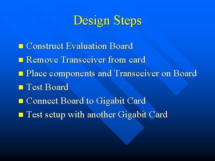
Design Steps Construct Evaluation Board n Remove Transceiver from card n Place components and Transceiver on Board n Test Board n Connect Board to Gigabit Card n Test setup with another Gigabit Card n
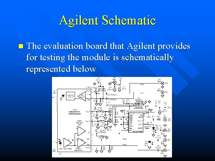
Agilent Schematic n The evaluation board that Agilent provides for testing the module is schematically represented below
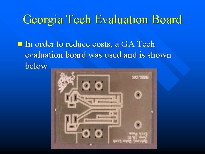
Georgia Tech Evaluation Board n In order to reduce costs, a GA Tech evaluation board was used and is shown below
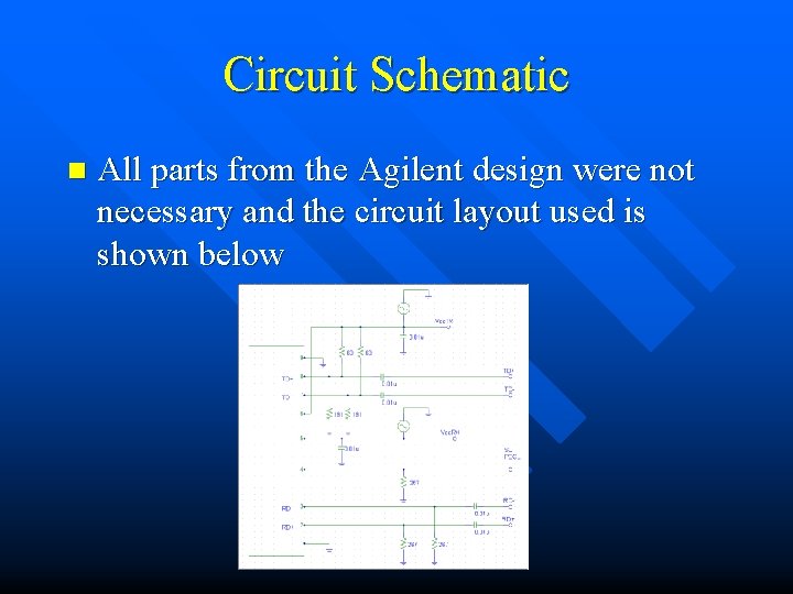
Circuit Schematic n All parts from the Agilent design were not necessary and the circuit layout used is shown below

Primary Design Considerations n Power Supply Filtering Circuit n Transmission Lines and Terminations

Power Supply Filtering Circuit n Agilent Board: Circuit was included to keep both parts of the transceiver independent of their power supply considerations n Our Board: Eliminated the need for the circuit by having two separate power supplies for both parts of the module
Transmission Lines and Terminations n Transmission lines were eliminated from our boards – Care was taken to keep the length of the lines less than 1/10 th the signal wavelength i. e. 6 cm – Sharp angles on the board were avoided
Miscellaneous Considerations n Reduce susceptibility to noise – Accomplished by using differential inputs as opposed to single-ended ones n Top and bottom of board unconnected – Used vias to connect the two

Component Details n Capacitors mainly used for Decoupling – Capacitors used to separate power supplies from circuit. – Protect circuits from transients n Resistors used for terminations and biasing
Problems Faced n Soldering – surface mount components n Top and Bottom of board unconnected – Power not getting through from one side to another – Solved by allowing solder to drip through to form a connection
Connecting Card to Board Used RG 174 Cable with SMA connectors to connect card to board n Removed resistor networks from Gigabit card n Used wire to connect signal detect pin from board to card n Connected the grounds of board and card with wire n
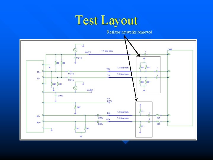
Test Layout Resistor networks removed
Results Eye diagrams and bit error rate data
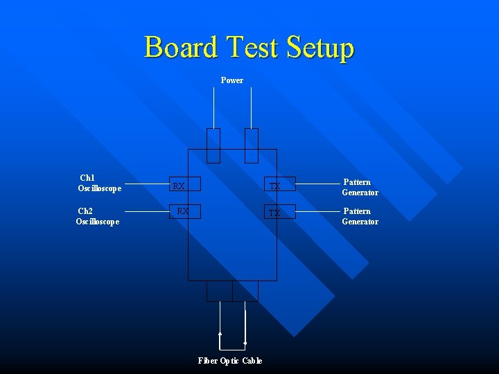
Board Test Setup Power Ch 1 Oscilloscope Ch 2 Oscilloscope RX RX Fiber Optic Cable TX Pattern Generator
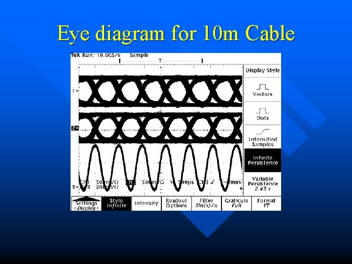
Eye diagram for 10 m Cable
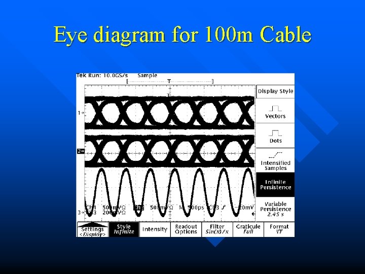
Eye diagram for 100 m Cable
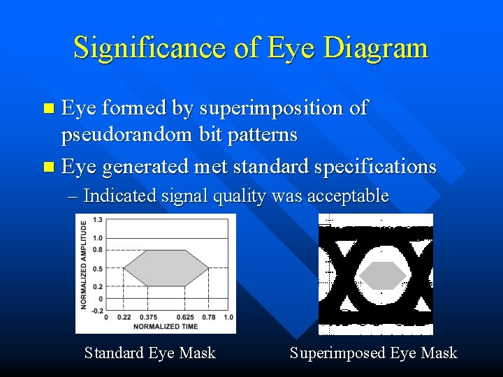
Significance of Eye Diagram Eye formed by superimposition of pseudorandom bit patterns n Eye generated met standard specifications n – Indicated signal quality was acceptable Standard Eye Mask Superimposed Eye Mask
Bit Error Rate Data n 10 m cable: No errors encountered n 100 m cable: No errors encountered n Errors appeared when using PN 23 encoding scheme at 1. 2 Gbps – Error rate = 2. 3 errors/Mb
Verification of results Card was plugged into computer n Passed loop-back diagnostic test n Connected to another computer using fiber optic cable n Packets sent and received with no errors n File transferred successfully over link n
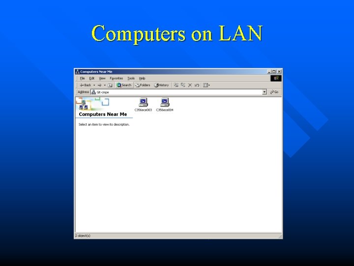
Computers on LAN
Summary The card was assembled and tested successfully n Questions? n – Harsh Sopory (gte 648 h) – Kaushik Narayanan (gte 678 h) – Nafeez Bin Taher (gte 078 h)
- Slides: 32