
GIF implementation Adrian Fabich Sylvain Girod Dorothea Pfeiffer

GIF++ implementation Adrian Fabich, Sylvain Girod, Dorothea Pfeiffer, EN-MEF-LE GIF++ 3 rd users’ meeting, 11 th July 2013
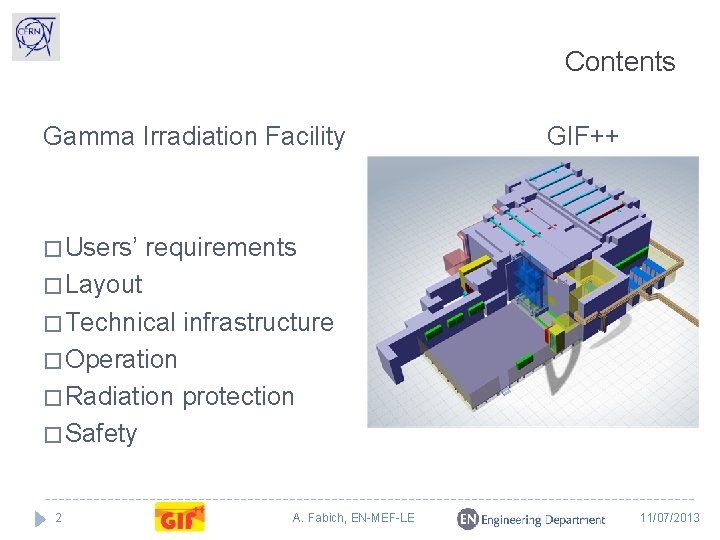
Contents Gamma Irradiation Facility � Users’ GIF++ requirements � Layout � Technical infrastructure � Operation � Radiation protection � Safety 2 A. Fabich, EN-MEF-LE 11/07/2013
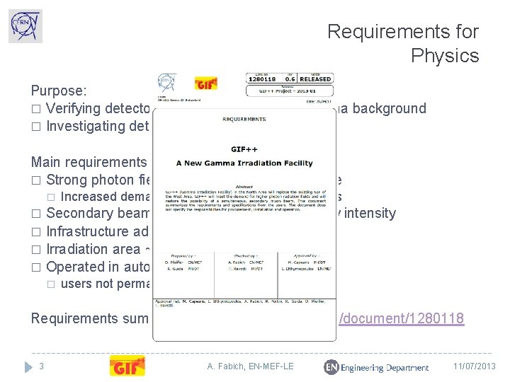
Requirements for Physics Purpose: � Verifying detector performance in strong gamma background � Investigating detector ageing Main requirements � Strong photon field (background) from a source � Increased demands also in view of LHC upgrades Secondary beam (signal): primarily muons, low intensity � Infrastructure adequate for gaseous detectors � Irradiation area ~100 m 2 � Operated in autonomous mode � � users not permanently present Requirements summarized in http: //edms. cern. ch/document/1280118 3 A. Fabich, EN-MEF-LE 11/07/2013
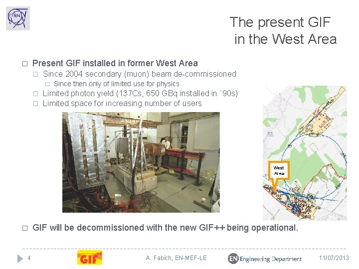
The present GIF in the West Area � Present GIF installed in former West Area � Since 2004 secondary (muon) beam de-commissioned � � � Since then only of limited use for physics Limited photon yield (137 Cs, 650 GBq installed in `90 s) Limited space for increasing number of users West Area � 4 GIF will be decommissioned with the new GIF++ being operational. A. Fabich, EN-MEF-LE 11/07/2013
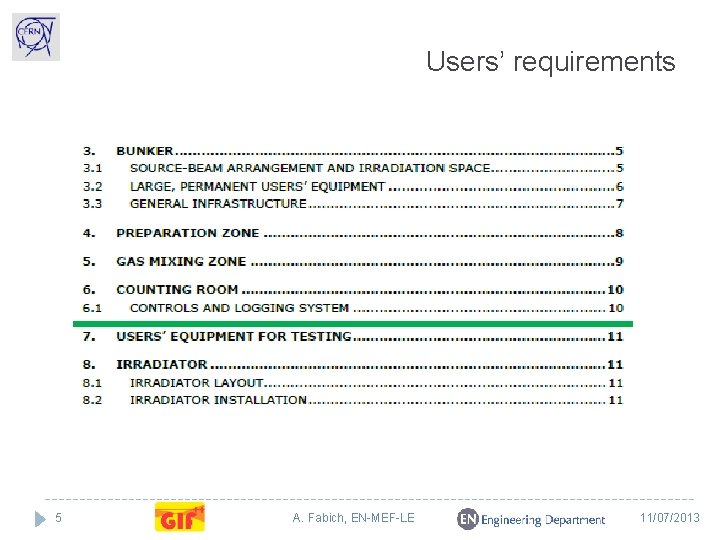
Users’ requirements 5 A. Fabich, EN-MEF-LE 11/07/2013
PH responsibilities � Defining users’ requirements � Irradiator procurement On-going: � Equipment in the gas (mixing) zone � analysers, mixers … + ATEX conformity of permanent m-detectors � Slow control of irradiator, gas equipment, logging � DAQ system USING THE FACILITY � Construction 6 A. Fabich, EN-MEF-LE 11/07/2013
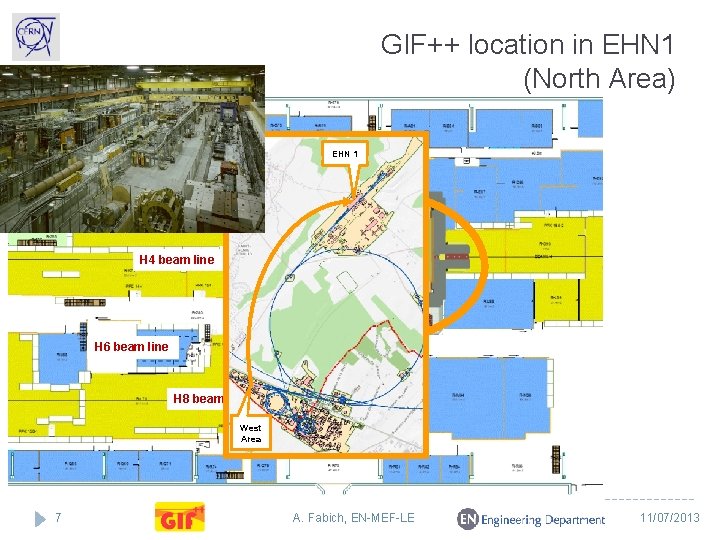
GIF++ location in EHN 1 (North Area) EHN 1 H 2 beam line GIF++ H 4 beam line H 6 beam line H 8 beam line West Area 7 A. Fabich, EN-MEF-LE 11/07/2013
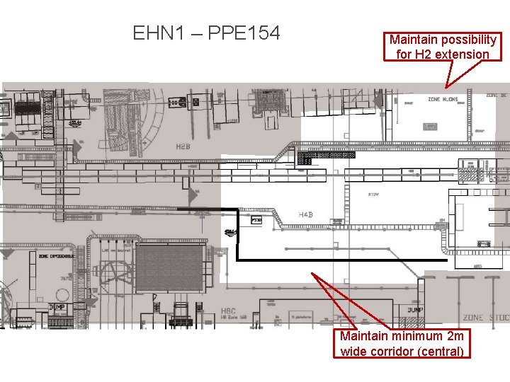
EHN 1 – PPE 154 Maintain possibility for H 2 extension Maintain minimum 2 m wide corridor (central) 8 A. Fabich, EN-MEF-LE 11/07/2013
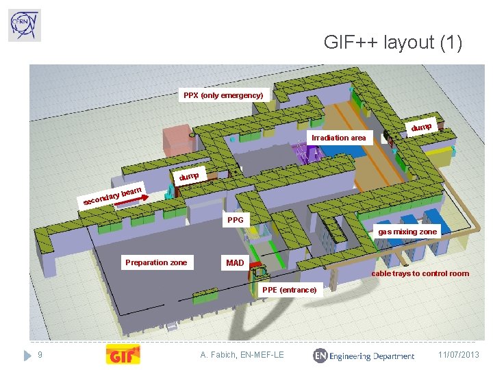
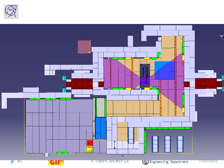
GIF++ layout (1) PPX (only emergency) dump Irradiation area dump am ry be nda seco PPG gas mixing zone Preparation zone MAD cable trays to control room PPE (entrance) 9 A. Fabich, EN-MEF-LE 11/07/2013
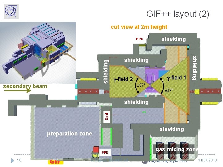
GIF++ layout (2) cut view at 2 m height secondary beam shielding g-field 1 g-field 2 shielding PPX ± 37° shielding PPG shielding preparation zone PPE 10 A. Fabich, EN-MEF-LE gas mixing zone 11/07/2013
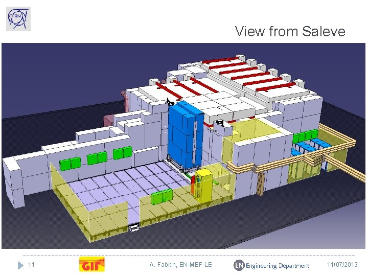
View from Saleve 11 A. Fabich, EN-MEF-LE 11/07/2013
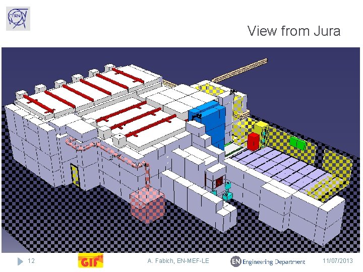
View from Jura 12 A. Fabich, EN-MEF-LE 11/07/2013
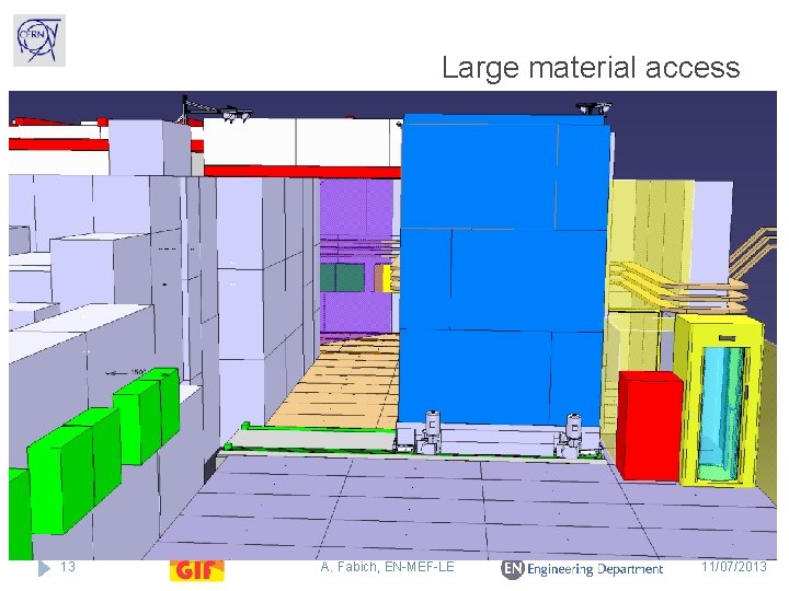
Large material access 13 A. Fabich, EN-MEF-LE 11/07/2013
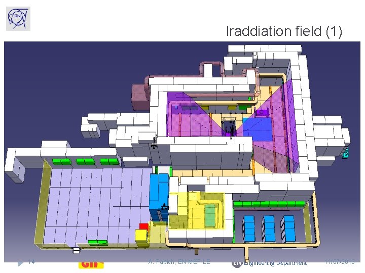
Iraddiation field (1) 14 A. Fabich, EN-MEF-LE 11/07/2013
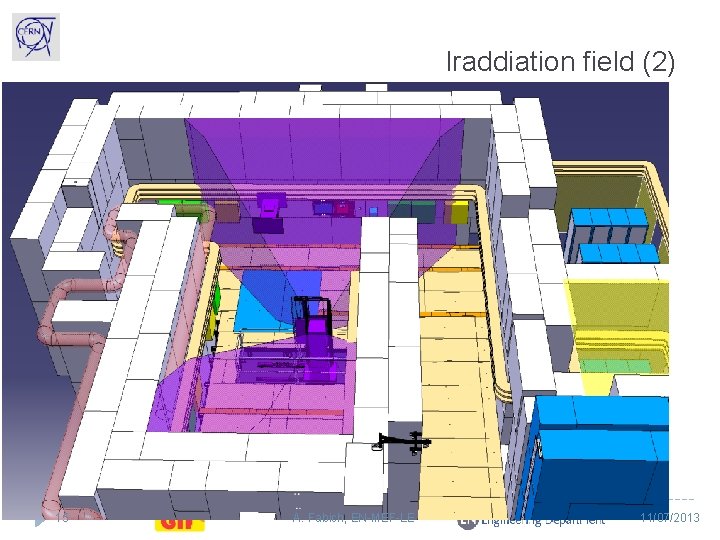
Iraddiation field (2) 15 A. Fabich, EN-MEF-LE 11/07/2013
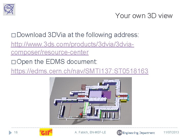
Your own 3 D view � Download 3 DVia at the following address: http: //www. 3 ds. com/products/3 dviacomposer/resource-center � Open the EDMS document: https: //edms. cern. ch/nav/SMTI 137: ST 0518163 16 A. Fabich, EN-MEF-LE 11/07/2013
Secondary muon beam From T 2 target 99% of beam are within 10 cm x 10 cm, remainder spread over 1 m 2 � Main user mode: couple of periods per year with each about two weeks duration � Parasitic mode with muons: as much as possible (based on experience from previous years, one can expect parasitic muon beams for about 30 -50% of the beam time, equivalent to about 2 -4 months/year). � Few periods per year of approximately two weeks duration in which a beam pipe is installed within the facility and electron beam is taken by CMS ECAL downstream from GIF++ 17 A. Fabich, EN-MEF-LE 11/07/2013
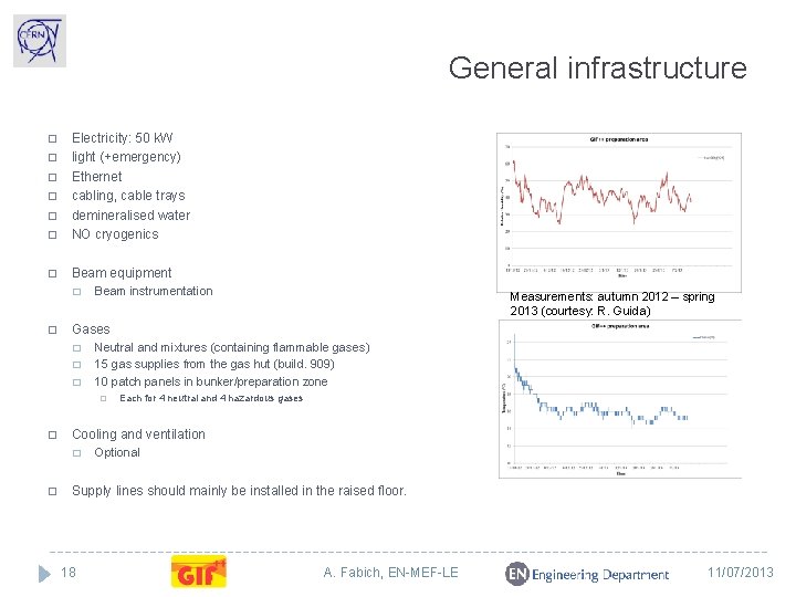
General infrastructure � Electricity: 50 k. W light (+emergency) Ethernet cabling, cable trays demineralised water NO cryogenics � Beam equipment � � � � Beam instrumentation Gases � � � Neutral and mixtures (containing flammable gases) 15 gas supplies from the gas hut (build. 909) 10 patch panels in bunker/preparation zone � � Each for 4 neutral and 4 hazardous gases Cooling and ventilation � � Measurements: autumn 2012 – spring 2013 (courtesy: R. Guida) Optional Supply lines should mainly be installed in the raised floor. 18 A. Fabich, EN-MEF-LE 11/07/2013
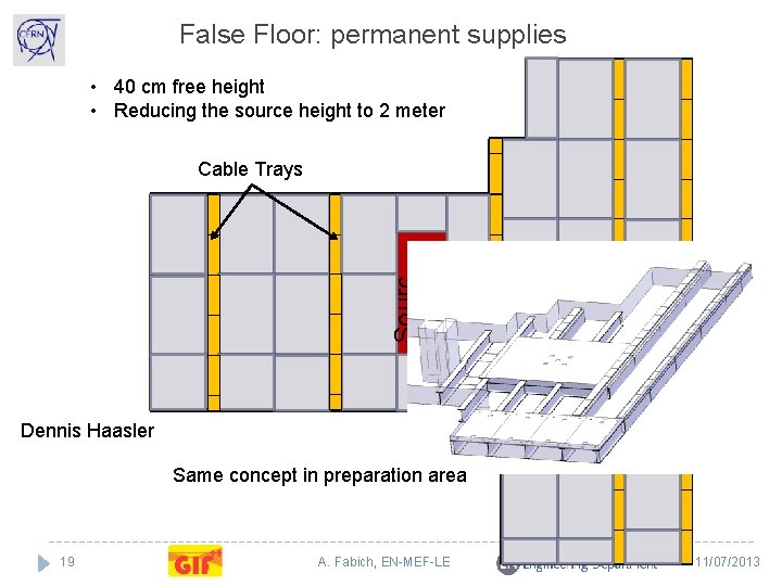
False Floor: permanent supplies • 40 cm free height • Reducing the source height to 2 meter Sourc e Cable Trays Ground Trigger Dennis Haasler Same concept in preparation area 19 A. Fabich, EN-MEF-LE 11/07/2013
20 A. Fabich, EN-MEF-LE 11/07/2013
3000 mm 21 A. Fabich, EN-MEF-LE 11/07/2013
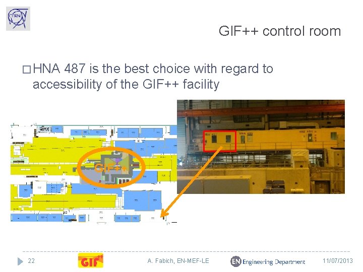
GIF++ control room � HNA 487 is the best choice with regard to accessibility of the GIF++ facility GIF++ 22 A. Fabich, EN-MEF-LE 11/07/2013
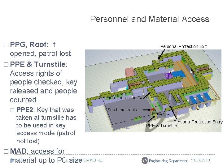
Personnel and Material Access � PPG, Roof: If opened, patrol lost � PPE & Turnstile: Access rights of people checked, key released and people counted � Personal Protection Exit Personal Protection Gate PPE 2: Key that was taken at turnstile has to be used in key access mode (patrol not lost) access for 23 Fabich, EN-MEF-LE material up to PCA. size Small material access Pre Zone Personal Protection Entry PPE & Turnstile � MAD: 11/07/2013
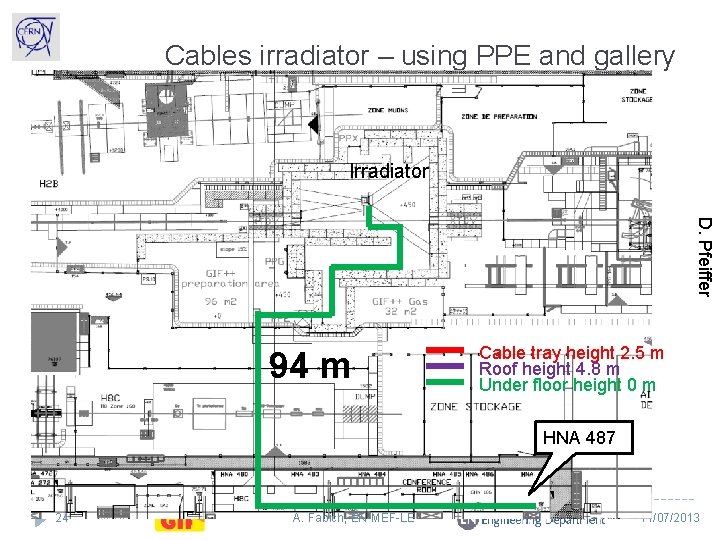
Cables irradiator – using PPE and gallery Irradiator D. Pfeiffer 94 m Cable tray height 2. 5 m Roof height 4. 8 m Under floor height 0 m HNA 487 24 A. Fabich, EN-MEF-LE 11/07/2013
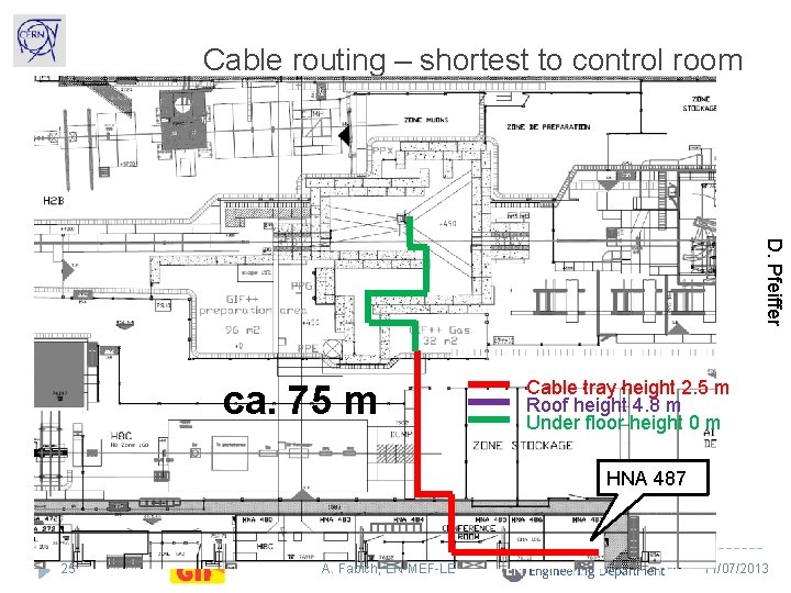
Cable routing – shortest to control room D. Pfeiffer ca. 75 m Cable tray height 2. 5 m Roof height 4. 8 m Under floor height 0 m HNA 487 25 A. Fabich, EN-MEF-LE 11/07/2013
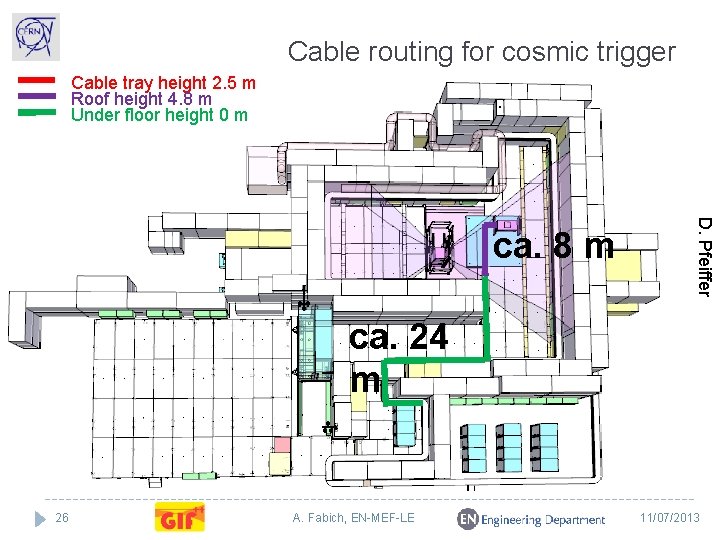
Cable routing for cosmic trigger Cable tray height 2. 5 m Roof height 4. 8 m Under floor height 0 m D. Pfeiffer ca. 8 m ca. 24 m 26 A. Fabich, EN-MEF-LE 11/07/2013
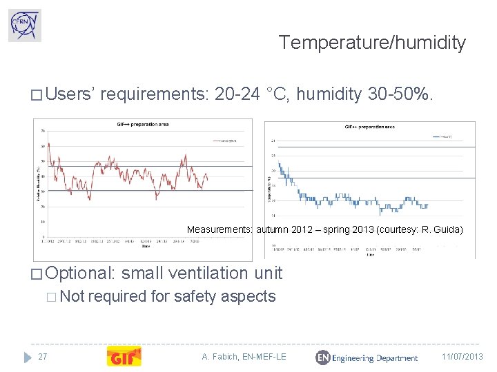
Temperature/humidity � Users’ requirements: 20 -24 °C, humidity 30 -50%. Measurements: autumn 2012 – spring 2013 (courtesy: R. Guida) � Optional: � Not 27 small ventilation unit required for safety aspects A. Fabich, EN-MEF-LE 11/07/2013
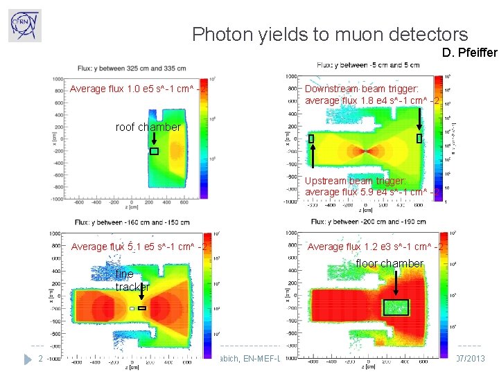
Photon yields to muon detectors D. Pfeiffer Average flux 1. 0 e 5 s^-1 cm^ -2 Downstream beam trigger: average flux 1. 8 e 4 s^-1 cm^ -2 roof chamber Upstream beam trigger: average flux 5. 9 e 4 s^-1 cm^ -2 Average flux 5. 1 e 5 s^-1 cm^ -2 floor chamber fine tracker 28 Average flux 1. 2 e 3 s^-1 cm^ -2 A. Fabich, EN-MEF-LE 11/07/2013
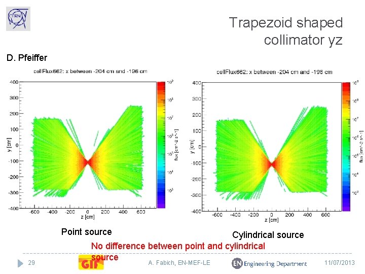
Trapezoid shaped collimator yz D. Pfeiffer Point source 29 Cylindrical source No difference between point and cylindrical source A. Fabich, EN-MEF-LE 11/07/2013
Safety responsibility for implementation with SBA (together with CERN expert groups) � Radiation shielding � Flammable gas detection and ODH (in bunker) � Fire detection � Access system/personnel protection � Interlock(s), also with irradiator � Gas 30 zone: ATEX conform (PH) A. Fabich, EN-MEF-LE 11/07/2013
GIF++ irradiation zone The irradiation zone hosting the irradiator � is a controlled area (PPE 154). � inside a supervised area (EHN 1). � No risk of activation due to low intensities of secondary beam � Presence of high intensity photon source requires additional precautions due to the prompt radiation levels: Extended shielding � Access system � Entrance chicanes � 31 A. Fabich, EN-MEF-LE 11/07/2013
Risk analysis � Carried out with general safety, radiation protection, equipment owners and access system. � Radiation simulation for conceptual layout available � � Defines required shielding � Full scale radiation simulation by end summer 2013 Needs for maintenance � � Regular inspection of irradiator system by CERN-RP and vendor Operations � Access � Controls � Standard procedure(s) of EHN 1 apply. No additional implications by the presence of the photon source. � Incidents � Additional hazards � � Gases (non and flammable) � Electricity � Heavy handling � Civil engineering (concrete walls up to 6. 5 m high) Safety file is in preparation. 32 A. Fabich, EN-MEF-LE 11/07/2013
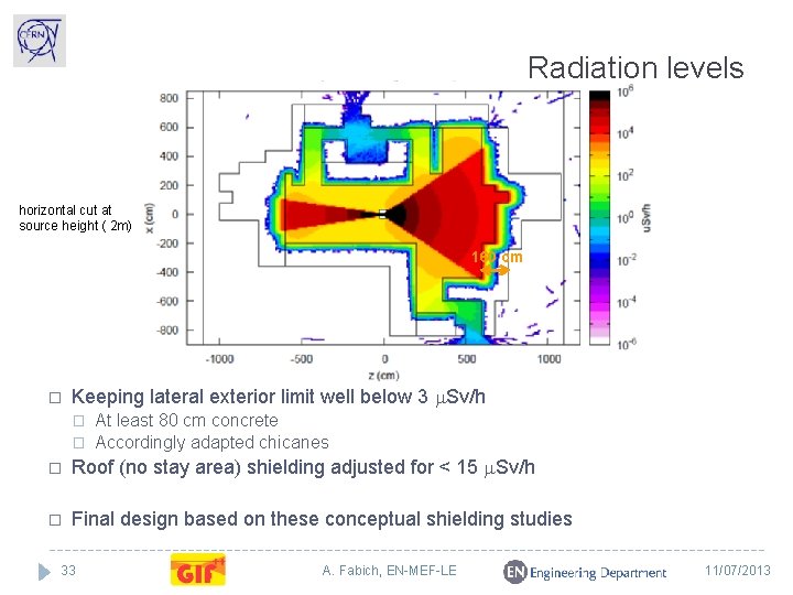
Radiation levels horizontal cut at source height ( 2 m) 160 cm � Keeping lateral exterior limit well below 3 m. Sv/h � � At least 80 cm concrete Accordingly adapted chicanes � Roof (no stay area) shielding adjusted for < 15 m. Sv/h � Final design based on these conceptual shielding studies 33 A. Fabich, EN-MEF-LE 11/07/2013
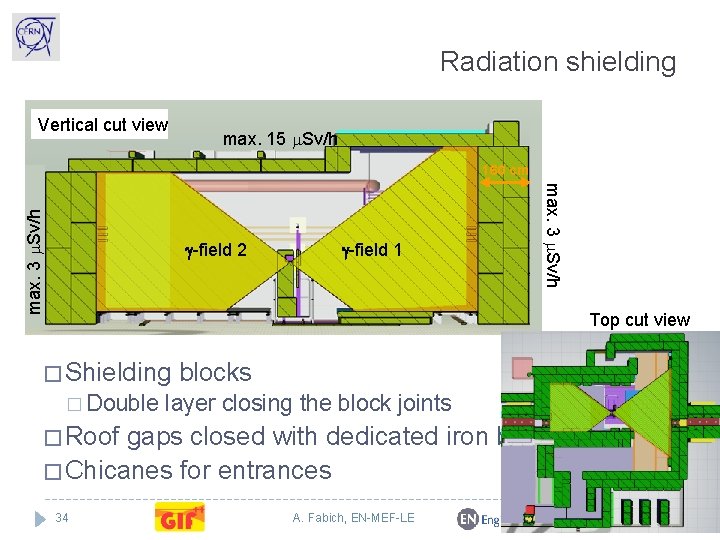
Radiation shielding Vertical cut view max. 15 m. Sv/h g-field 2 g-field 1 max. 3 m. Sv/h 160 cm Top cut view � Shielding � Double blocks layer closing the block joints � Roof gaps closed with dedicated iron beams � Chicanes for entrances 34 A. Fabich, EN-MEF-LE 11/07/2013
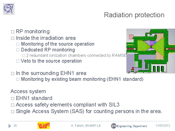
Radiation protection � RP monitoring � Inside the irradiation area Monitoring of the source operation � Dedicated RP monitoring � � In � 2 redundant ionization chambers connected to RAMSES Veto to the source operation the surrounding EHN 1 area Monitoring by existing beam monitoring (EHN 1 standard) Access system � EHN 1 standard � Access safety elements compliant with SIL 3 � Single Access System (SAS) for counting persons in the area. 35 A. Fabich, EN-MEF-LE 11/07/2013
Operational controls � Users’ interface: CESAR � For personnel access and beam control Standard HW/SW integration into SBA controls environment � Access controls � Beam controls � Safety elements � Irradiator provided with its own console. Only link to SBA controls via veto line and status logging. 36 A. Fabich, EN-MEF-LE 11/07/2013
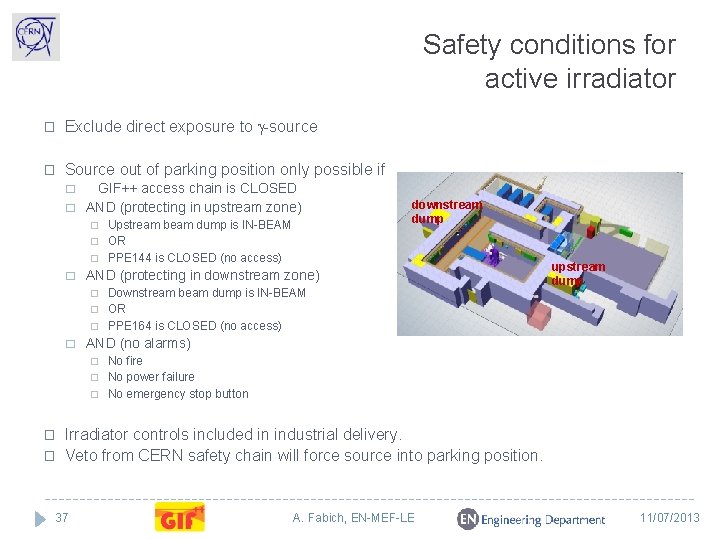
Safety conditions for active irradiator � Exclude direct exposure to g-source � Source out of parking position only possible if � � GIF++ access chain is CLOSED AND (protecting in upstream zone) Upstream beam dump is IN-BEAM � OR � PPE 144 is CLOSED (no access) � � downstream dump AND (protecting in downstream zone) Downstream beam dump is IN-BEAM � OR � PPE 164 is CLOSED (no access) upstream dump � � AND (no alarms) No fire � No power failure � No emergency stop button � � � Irradiator controls included in industrial delivery. Veto from CERN safety chain will force source into parking position. 37 A. Fabich, EN-MEF-LE 11/07/2013
Next steps � Safety file to be completed until August 2013 � Risk analysis � Full scale radiation simulation based on final layout � Construction starts in September 2013 � Commissioning � Expecting 38 with beam in autumn 2014 irradiator delivery in September 2014 A. Fabich, EN-MEF-LE 11/07/2013
Spare slides � SPARE 39 SLIDES A. Fabich, EN-MEF-LE 11/07/2013
40 A. Fabich, EN-MEF-LE 11/07/2013
- Slides: 40