Geometry of Aerial Photographs Aerial Cameras Aerial cameras

: – Geometrically stable –")


 L:")

 Aerial Photos are: 1 - Vertical or tilted •")
 2 - Oblique Photos If the optical axis is")
 2 - Oblique Photos • Low oblique • High")


 3 - Convergent Photographs Low oblique photos in which")

 • We use positives for • Measurements can be as ease")
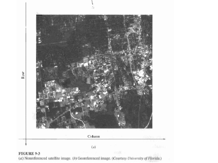
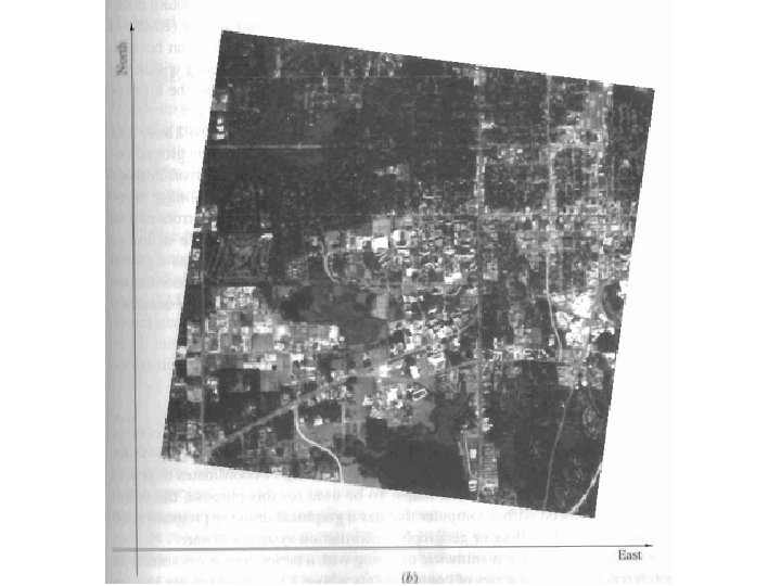
 • Pixels in a digital image represent coordinates of rows and")


")
")
 rb/R = f/(H-h)")
 of a point wrt a point on the datum")


- Slides: 75
Geometry of Aerial Photographs
Aerial Cameras • Aerial cameras must be (details in lectures): – Geometrically stable – Have fast and efficient shutters – Have high geometric and optical quality lenses • They can be classified according to type of frame: – Single lens Frame – Multiple frame – Strip Frame – Panoramic • They can also be either film or digital cameras. THIS COURSE WILL DISCUSS ONLY SINGLE FRAME CAMERAS
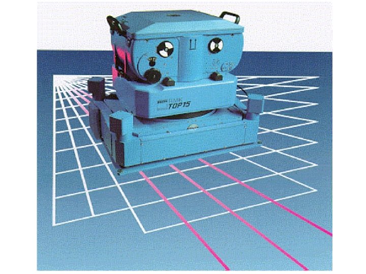
Aerial camera with viewfinder and electronic control
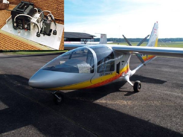
Aerial Camera in action
Single lens Frame Cameras •
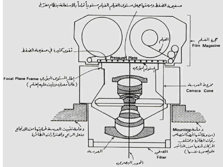
Components of a single frame film camera. Three main parts: 1. Magazine 2. Body 3. Lens cone assembly Components and notes to be discussed din lecture
Components of a single frame film camera. Fiducial Marks A vertical Photograph
Components of a single frame film camera. Example of a corner Fiducial Mark under Magnification
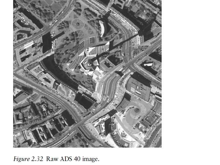
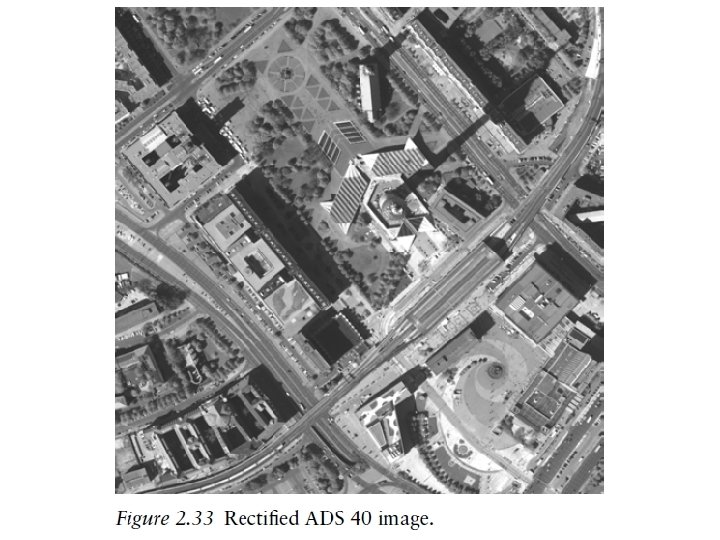
Airborne and Spaceborne Imagery
Geometry of aerial cameras Principal Point (P. P) L:
Geometry of aerial cameras Identify the following: L: perspective center. Fiducial Center F. C. Principal Point (P. P) or O: the point where the perpendicular from the perspective center intersects the photograph. Usually deviates from the F. C by a very small distance. - Principal axis: the line perpendicular from the principal center on the plane of the photograph (negative). - f the focal length, equals the Principal Distance. • -
Types of Photographs (by tilt) Aerial Photos are: 1 - Vertical or tilted • Vertical photos are taken with the optical axis (Principal Line) vertical or tilted by no more than 2 • Tilted: if the optical axis is tilted by no more than 3
Types of Photographs (by tilt) 2 - Oblique Photos If the optical axis is intentionally strongly tilted to increase coverage, they are: • Low oblique: if the tilt is not enough to show the horizon, usually 3 to 30 Low Oblique Photo
Types of Photographs (by tilt) 2 - Oblique Photos • Low oblique • High oblique: if the horizon is shown on the photograph High oblique Low oblique
High Oblique Vertical Photograph y x
Example of vertical, high, and low oblique photos
Types of Photographs (by tilt) 3 - Convergent Photographs Low oblique photos in which camera axis converge toward one another Low Oblique Photo
Comparison between vertical and oblique photos Coverage Geometry Low cloud? View: issues with tall features and views of sides of features. • Others • •
Photo Coordinates (film) • We use positives for • Measurements can be as ease of geometry and accurate as 1 micron = familiarity of feature 1/1000 mm y shapes, negatives may be used in certain applications • Lines connecting middle fiducials ON THE POSITIVE define a photo coordinate system, in which x is in the direction of flight, A RIGHT-HAND coordinate system x
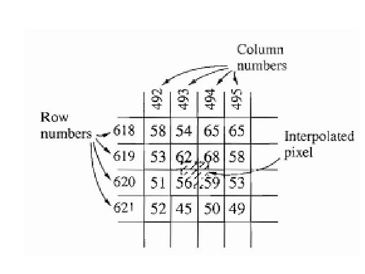
Photo Coordinates (digital) • Pixels in a digital image represent coordinates of rows and columns.
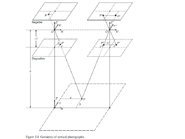
Geometry of a vertical photographs • The line Lo. O, the optical axis is assumed truly vertical Direction of flight
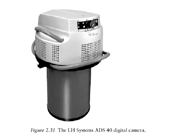
Geometry of a digital frame camera • Similar geometry is assumed in case of a digital camera • Uses a two dimensional array of CCD elements mounted at the focal plane of the camera. • The image is a grid of picture elements (pixels)
• Similar geometry is assumed in case of a digital camera • Uses a two dimensional array of CCD elements mounted at the focal plane of the camera. • The image is a grid of picture elements (pixels) • The size of pixels in one image represent the resolution of the image, the smaller the pixel, the higher (better) the resolution. • A mega (million) pixel image includes one million pixel • Number of pixels can be as low as 500 X 500 = 250, 000 pixels, or megas of pixels for commercial cameras, or gegapixels in classified cameras. • What is the size of image of a camera that includes a CCD frame sensor, that is 1024 X 1024 elements, if the size of a pixels is 5 ? How many megapixels are there? Answer: image size = 1024 X 0. 005 = 5. 12 mm, No of pixels = 1024 X 1024= 1 mega pixel
Digital image resolution
image taken from a firstgeneration Landsat satellite over Milwaukee, Wisconsin.
1 -m resolution image obtained from the IKONOS satellite showing San Francisco.
Concept of image pyramids
linear array sensors A linear CCD scans the ground at a given time. The vehicle advances a distance equals to one array and capture the next line. Will the entire image be scanned at the same time?
Flying spot scanner: The geometry is such that the after a row is finished being scanned, the vehicle advanced to the beginning of the next row. • Which digital system is suitable for what purpose? ? • Why? ?
Image coordinate corrections Our goal is to measure photo coordinates and relate them to ground coordinates by equations to obtain ground coordinates. Once you have ground coordinates, you can draw a map, establish cross section, etc. Measured photo coordinates need to be corrected prior to substation in equations, for the following: • Film shrinkage • Principal point location • Lens distortions • Atmospheric refraction • Earth curvature • Which of the corrections inapplicable for digital images? ?
Effect of Earth Curvature
Atmospheric Refraction
Vertical Photographs
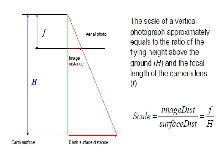
Scale of a Vertical Photograph • Scale of a photograph is the ratio of a distance on a photo to the same distance on the ground. • Photographs are not maps, why? • Scale of a map and scale of a photograph. • Orthphotos (orthophoto maps), what are they? • Scale (s) at any point: S = f H - h • Average scale of a photograph: Savg = f H - h avg If the f, H, and h are not available, but a map is available then: photo distance X map scale Photo Scale = map distance
Scale of a vertical photograph.
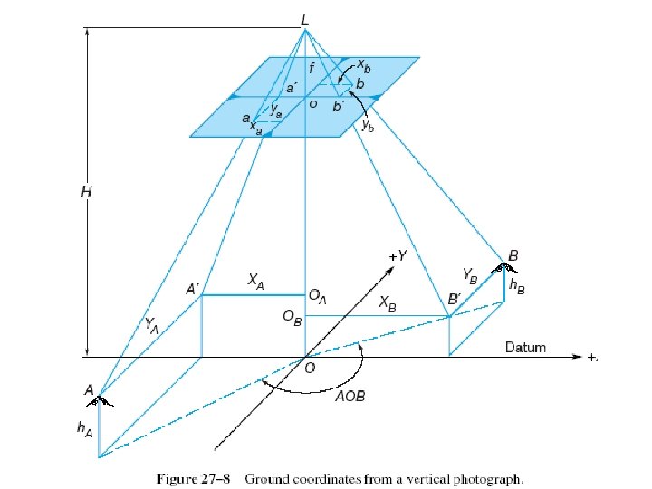
Ground Coordinates from a Single Vertical Photograph • With image coordinate system defined, we may define an arbitrary ground coordinate system parallel to (x, y) origin at nadir. • That ground system could be used to compute distances and azimuths. Coordinates can also be transformed to any system • In that ground system: Xa = xa * (photograph scale at a) Ya = ya * (photograph scale at a)
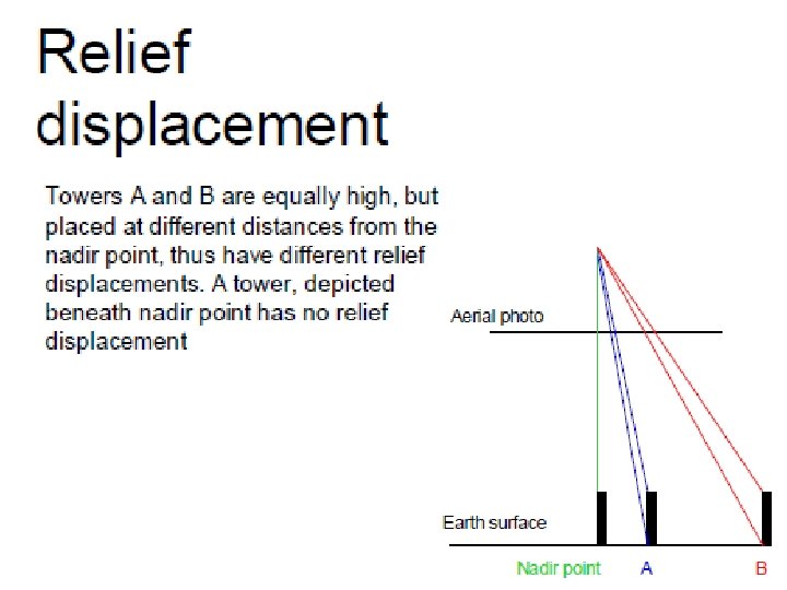
Relief Displacement on a Vertical Photograph • The shift of an image from its theoretical datum location caused by the object’s relief. Two points on a vertical line will appear as one line on a map, but two points, usually, on a photograph. • The displacement is from the photgraphic nadir point. In a vertical photo, the displacement is from the principal point, which is the nadir in this case. • Photographic Nadir point is where the vertical from the Exposure Station intersects the photograph.
Relief displacement from Nadir (enlarged)
Relief displacement from Nadir (Center )
ra/R = f/H Or: ra *H = R * f ----(1) rb/R = f/(H-h) Or: rb * (H-h) =R * f ---(2) Then from (1) and (2); ra *H = rb * (H-h) then; (rb* H) – (ra*H) = rb h d = rb - ra = rb *hb /H Now, what about b and c? What would dc wrt b equals?
• Relief displacement (d) of a point wrt a point on the datum : r h d = H where: r: is the radial distance on the photo to the high point h : elevation of the high point, and H is flying height above datum • Assuming that the datum is at the bottom of vertical object, H is the flying height above ground, the value h will compute the object height.
Or, in general: Assume that point C is vertically above B, they are shown on the photograph as (c) and (b). Measured radial distances from the center to points c and b (rc and rb) , then dc = rc - rb and; dc = (rc * htc) / (flying height above ground = H – hb) Answer: d = r h/ H’ , then H’ = 535 – 259 = 276 m H=
Tilted Photographs
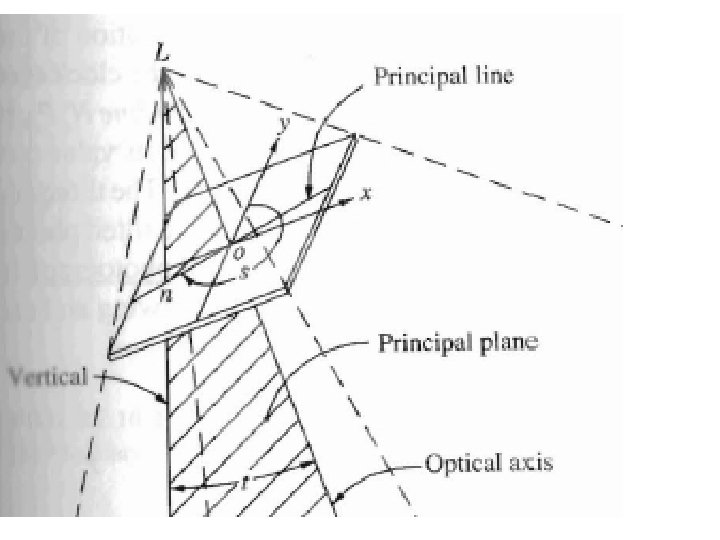
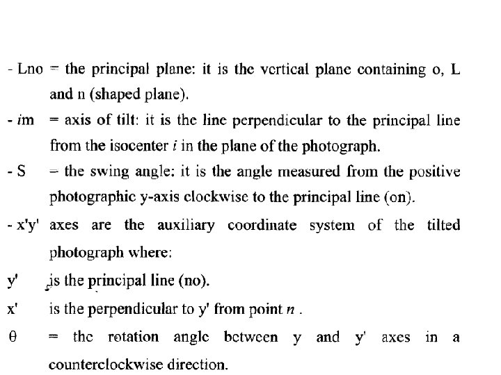
Basic elements of a tilted photographs • The optical axis is tilted from the vertical • Identify the following: - t = angle of tilt between the plumb line and the optical axis L 0
i i m
What and why an auxiliary coordinate system? • A step to relate photo coordinates to ground, because the photograph is tilted. • Thus, photo and ground coordinates are not parallel any more. • You need a system in between as a step to transfer photo coordinates to ground, specially that tilt is variable.
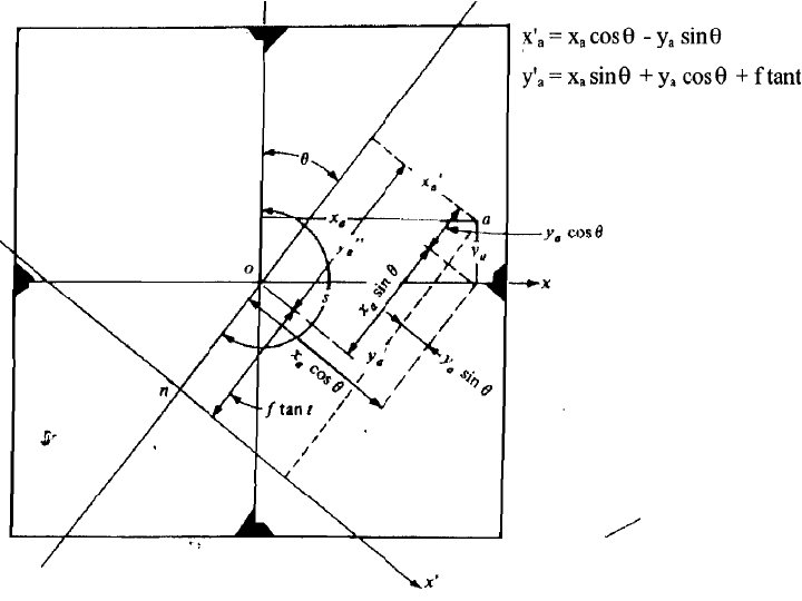
Tr dis ans ta itio n o f t nc an e f a t Transformation from photo coordinates (x, y) to an auxiliary coordinate system (x’, y’) y Rot y’ atio n o f ang le x S Note that = S - 180 x’
Relationship between Photo and Auxiliary coordinate system
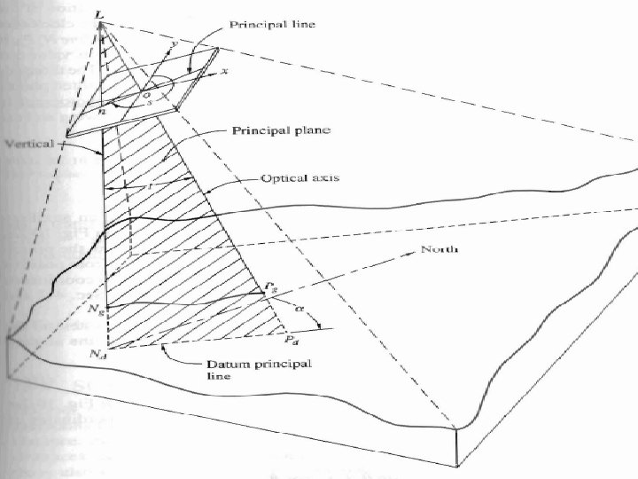
Scale of a tilted Photograph The tilt of a photograph occurs around the axis of tilt in the direction of the principal line. L y’ c n Pri o n i Axi s o f Ti lt x’ e Lin l ipa
Scale of a tilted Photograph • Scale = horizontal distance on the photo / horizontal distance on the ground = ka’ / KA’ = Lk / LK e P c rin ip Lin l a
S = Lk / LK, but: Lk = Ln – n. K = (f /cost t) – (y’ sin t), and y’ t n t f t
Also, LK = H - h. A = flying height above ground Then: H h. A Scale of a tilted photograph SA = f(sec t) – y’ sin t / (H-h. A)
Example
Ground Coordinates from a tilted photograph • Coordinates of point A in a ground coordinate system X’, Y’ where: • X’, Y’ are parallel to x’ and y’ (auxiliary system) • Ground Nadir N is the origin of the ground system • Note that in the auxiliary coordinate system, lines parallel to x’ are horizontal, thus x’ on the photo is horizontal and directly related to ground X by the scale, or X’A =x’ /SA
y’ t n • But in the auxiliary system, y’ is in the direction of maximum tilt and not horizontal, the scale is ratio between horizontal projections. • Ka: Horizontal projection of y’ = y’ cos t • Then, • Y’ = y’ cos t / S
Example