Geology 56606660 Applied Geophysics 31 Jan 2018 Last


- Slides: 13
Geology 5660/6660 Applied Geophysics 31 Jan 2018 Last time: The Refraction Method Cont’d • Dipping Layer Boundary: Requires reversed lines to separate dip from velocity Travel-times going “up-dip” (ud) and “down-dip” (dd) are: Can calculate velocities, dip angle , and thickness by inverting the travel-time equations: • Refract solves for multiple dipping layers using the Adachi formulation… Read for Fri 2 Feb: Burger 149 -167 (§ 4 -4. 1) © A. R. Lowry 2018
Some Limitations of the Refraction Method: • It does not get returns from low velocity layers. This means that not only does your best-fitting model not include the low velocity layer, but also estimates of the depth to top of all subsequent layers will be overestimated. • Thin layers may be aliased by geophone spacing, & in some cases will be missed regardless of spacing! As with the low velocity layer, this won’t affect velocity estimates for lower layers but will affect depth (in this case depth is underestimated).
: - Is this real?
water shale gas sand shale Example for a synthetic seismogram (Note however that just because the refraction isn’t the first arrival, doesn’t mean it isn’t there!)
What if velocity changes within layers? V 1 = 2000 m/s V 2 = 1000 m/s m = 1/V 1 m = 1/V 2
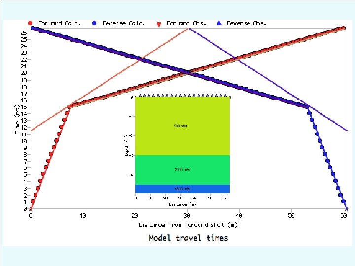
V 1 = 500 m/s V 2 = 2000 m/s V 3 = 1000 m/s m = 1/V 2 m = 1/V 3 m = 1/V 2 m = 1/V 1 m = 1/V 3 m = 1/V 1
What if the layer interface is not planar? B V 1 = 500 m/s z A V 2 = 2000 m/s m = 1/V 2 m = 1/V 1
B V 1 = 500 m/s z A V 2 = 2000 m/s Basically have a difference in the intercept times on one part of the geophone string relative to the other:
Refraction from an irregular surface: Delay-Time Method y E G h. E V 1 A B V 2 Define delay time as the time the ray traveled in layer 1 along a “slant path”, less the time it would have taken to travel the horizontal distance (AB) at velocity V 2. The total delay time EG traveling from E to G (or G to E) is where t. R is total travel time. Delay time under E is (This is half of the “time intercept” on our t–x plots!)
Using trigonometry and Snell’s law for the critical angle, We can’t measure it directly, but with reversed shots: E h. E A H V 1 B V 2 H from E ≈ H from G, and G
Refraction from an irregular surface: Delay-Time Method y x E H G V 1 V 2 Problem however: to get h. H from H, we need to know V 2! But we can also expect: ( a line with slope 2/V 2!)
1 i 2 V 1 V 2 Sometimes also called the “plus-minus method”: • Plot t 1 i–t 2 i vs xi for SP 1, SP 2 and all geophones i. Calculate V 2 from slope of the line fit (V 2 = 2/m). • At each geophone i, calculate thickness as