
Geological Space Probes Remote Sensing in Oil Wells
Geological Space Probes – Remote Sensing in Oil Wells (“Well Logging”) Roger Samworth
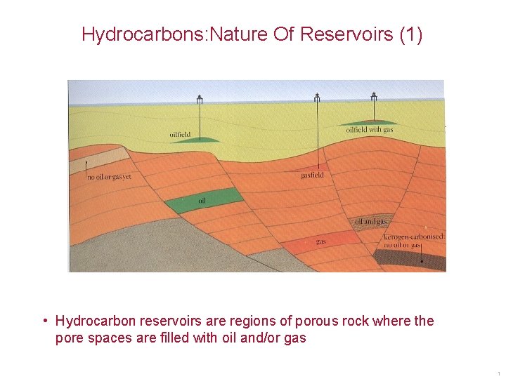
Hydrocarbons: Nature Of Reservoirs (1) • Hydrocarbon reservoirs are regions of porous rock where the pore spaces are filled with oil and/or gas 1

Hydrocarbons: Nature Of Reservoirs (2) • They usually occur at depths in the ground where the pressures are many thousands of p. s. i. And temperatures normally exceed 100 deg. C 2
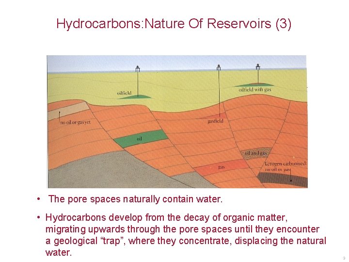
Hydrocarbons: Nature Of Reservoirs (3) • The pore spaces naturally contain water. • Hydrocarbons develop from the decay of organic matter, migrating upwards through the pore spaces until they encounter a geological “trap”, where they concentrate, displacing the natural water. 3
Hydrocarbons: Exploration And Production • 1. Identify geological structures • 2. Drill a borehole or “well” • 3. Lower remote sensing probes into the hole & “log the well” • 4. Cement steel pipe into hole • 5. Perforate pipe with shaped explosive charges • 6. Produce the hydrocarbon 4

Hydrocarbons: Exploration And Production • 1. Identify geological structures • 2. Drill a borehole or “well” • 3. Lower remote sensing probes into the hole & “log the well” • 4. Cement steel pipe into hole • 5. Perforate pipe with shaped explosive charges • 6. Produce the hydrocarbon 5
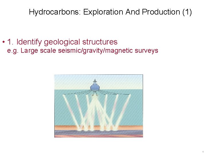
Hydrocarbons: Exploration And Production (1) • 1. Identify geological structures e. g. Large scale seismic/gravity/magnetic surveys 6
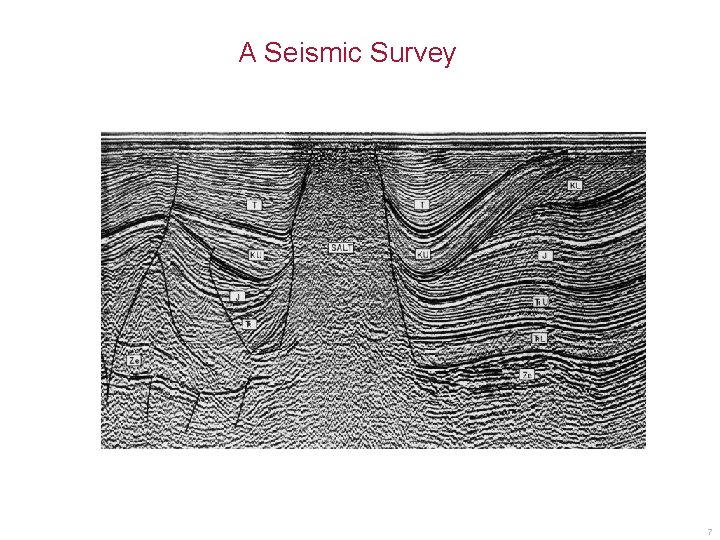
A Seismic Survey 7
Hydrocarbons: Exploration And Production • 1. Identify geological structures • 2. Drill a borehole or “well” • 3. Lower remote sensing probes into the hole & “log the well” • 4. Cement steel pipe into hole • 5. Perforate pipe with shaped explosive charges • 6. Produce the hydrocarbon 8
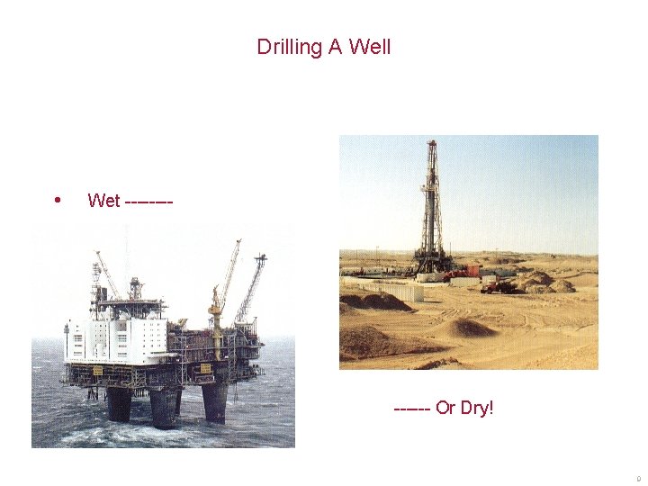
Drilling A Well • • Wet ------ Or Dry! 9
Hydrocarbons: Exploration And Production • 1. Identify geological structures • 2. Drill a borehole or “well” • 3. Lower remote sensing probes into the hole & “log the well” • 4. Cement steel pipe into hole • 5. Perforate pipe with shaped explosive charges • 6. Produce the hydrocarbon 10
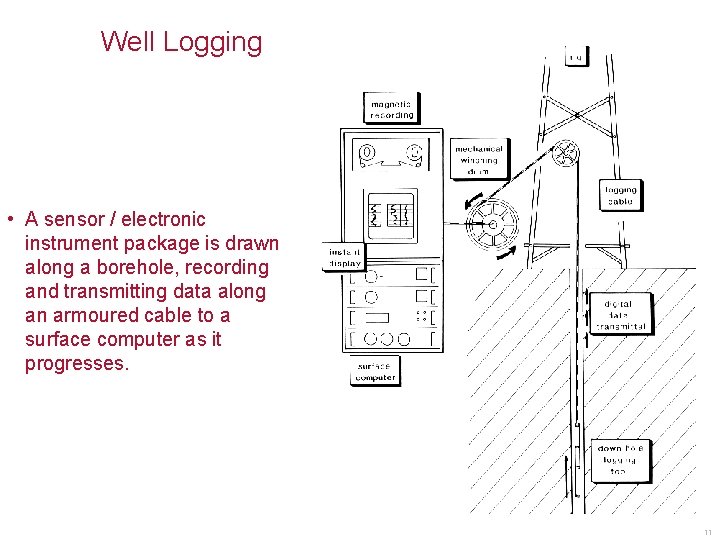
Well Logging • A sensor / electronic instrument package is drawn along a borehole, recording and transmitting data along an armoured cable to a surface computer as it progresses. 11
Well Logging - Parallels With Space Probes • Remote location - difficult to fix if it goes wrong • Hostile environment – Temperatures -40 deg. C ambient to 175+deg. C – Downhole pressures up to 15000+ p. s. i. – Corrosive fluids • Advanced materials required – Well logging probably biggest user of titanium outside aerospace – Extensive use of advanced polymers such as PEEK • Digital communications over long distances • Finite chance of not seeing (or hearing) the probe again ! 12
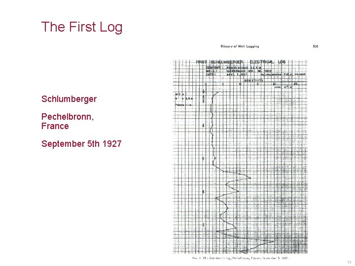
The First Log Schlumberger Pechelbronn, France September 5 th 1927 13
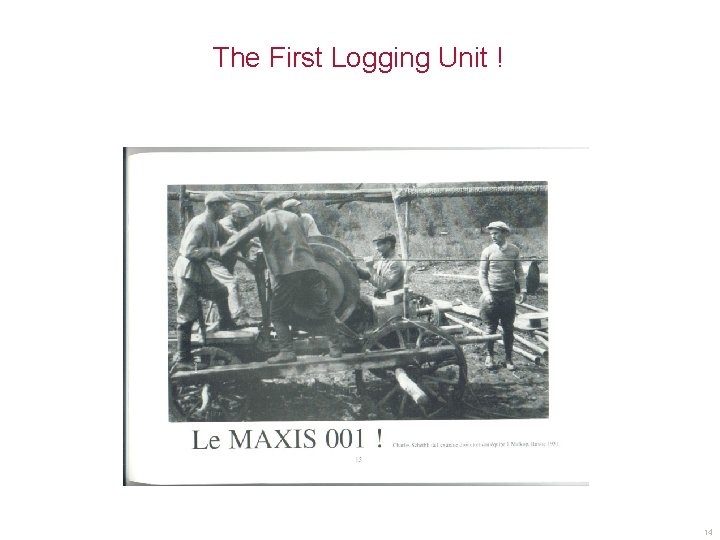
The First Logging Unit ! 14
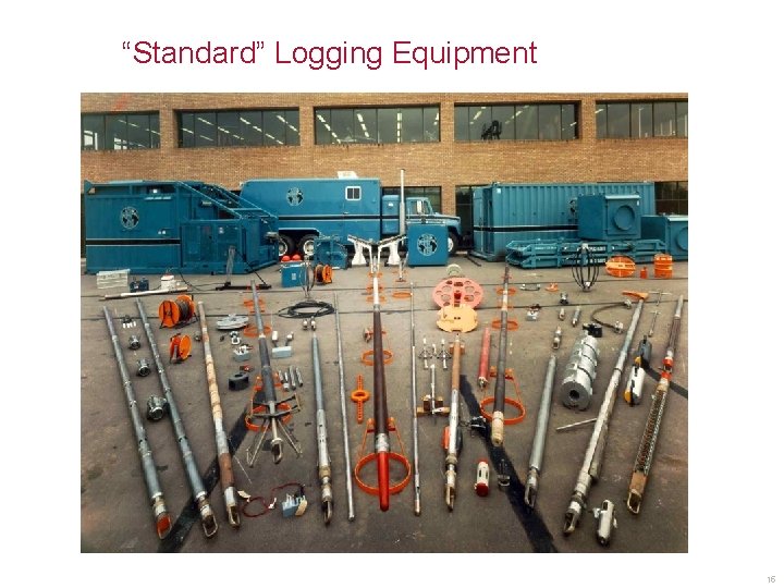
“Standard” Logging Equipment 15
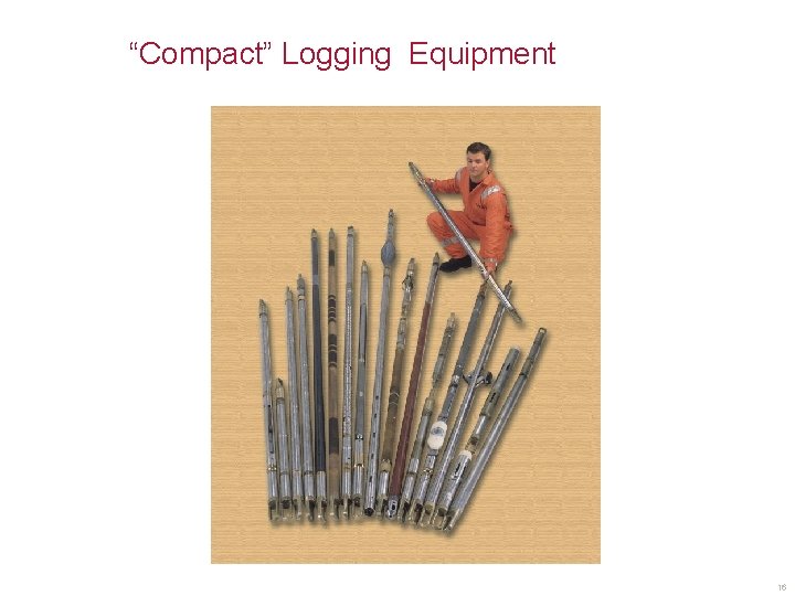
“Compact” Logging Equipment 16
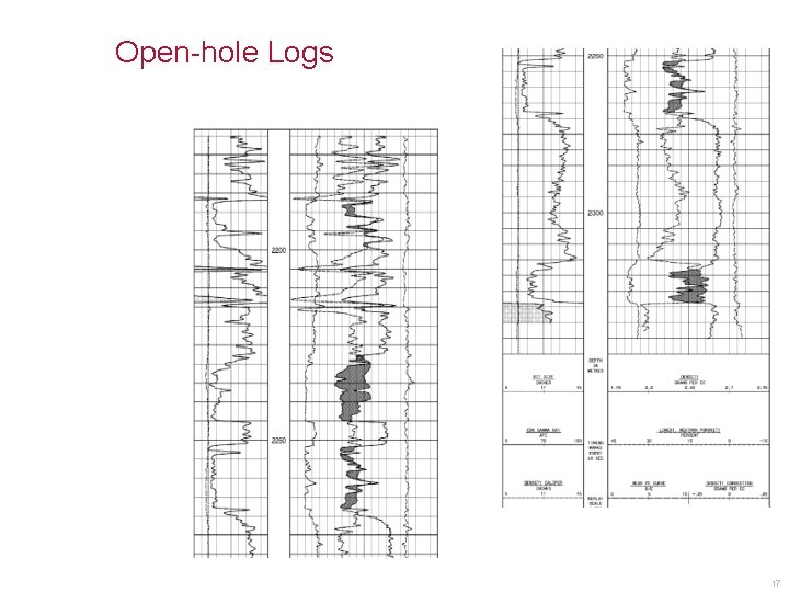
Open-hole Logs 17
Hydrocarbons: Exploration And Production • 1. Identify geological structures • 2. Drill a borehole or “well” • 3. Lower remote sensing probes into the hole & “log the well” • 4. Cement steel pipe into hole • 5. Perforate pipe with shaped explosive charges • 6. Produce the hydrocarbon 18
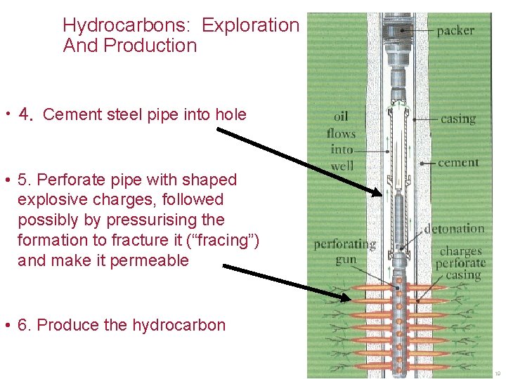
Hydrocarbons: Exploration And Production • 4. Cement steel pipe into hole • 5. Perforate pipe with shaped explosive charges, followed possibly by pressurising the formation to fracture it (“fracing”) and make it permeable • 6. Produce the hydrocarbon 19
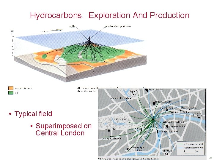
Hydrocarbons: Exploration And Production • Typical field • Superimposed on Central London 20
Logging The Well a) Identify Rock Type e. g. Measure level and nature of natural radioactivity b) Measure Rock Porosity e. g. Measure bulk density using gamma ray transport (Porous rocks are less dense) Measure hydrogen density using neutron transport (Both water & oil contain hydrogen) c) Identify Pore Fluids e. g. measure electrical resistivity low resistivity = water high resistivity = hydrocarbon d) Measure Rock Mechanical Properties e. g. measure acoustic velocities 21
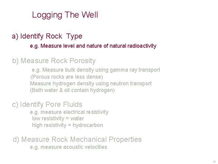
Logging The Well a) Identify Rock Type e. g. Measure level and nature of natural radioactivity b) Measure Rock Porosity e. g. Measure bulk density using gamma ray transport (Porous rocks are less dense) Measure hydrogen density using neutron transport (Both water & oil contain hydrogen) c) Identify Pore Fluids e. g. measure electrical resistivity low resistivity = water high resistivity = hydrocarbon d) Measure Rock Mechanical Properties e. g. measure acoustic velocities 22
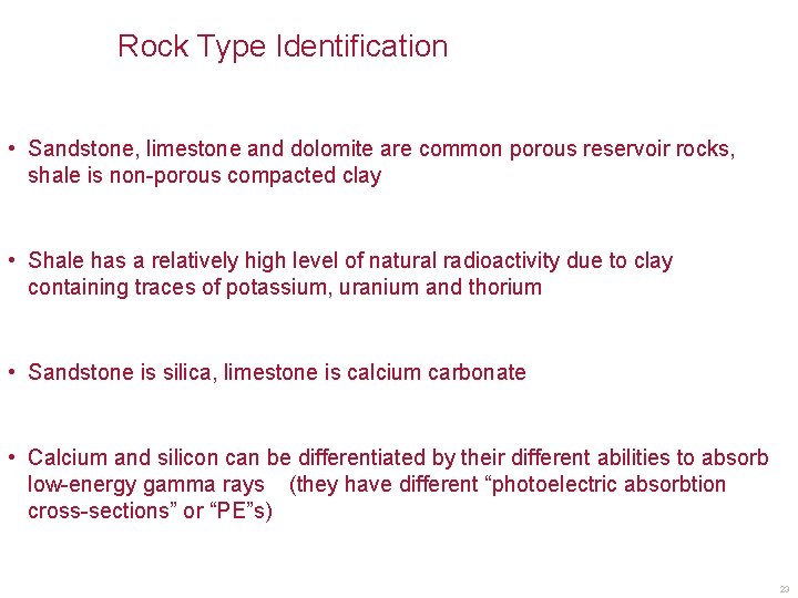
Rock Type Identification • Sandstone, limestone and dolomite are common porous reservoir rocks, shale is non-porous compacted clay • Shale has a relatively high level of natural radioactivity due to clay containing traces of potassium, uranium and thorium • Sandstone is silica, limestone is calcium carbonate • Calcium and silicon can be differentiated by their different abilities to absorb low-energy gamma rays (they have different “photoelectric absorbtion cross-sections” or “PE”s) 23
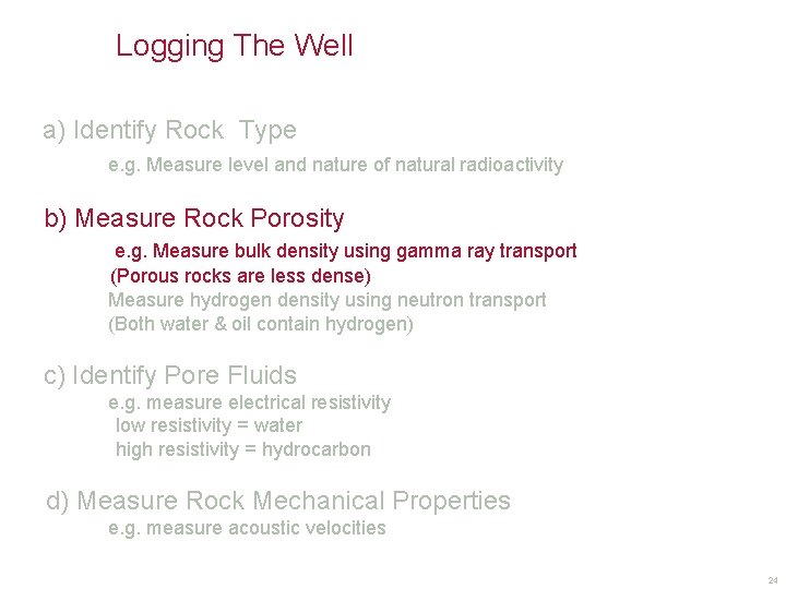
Logging The Well a) Identify Rock Type e. g. Measure level and nature of natural radioactivity b) Measure Rock Porosity e. g. Measure bulk density using gamma ray transport (Porous rocks are less dense) Measure hydrogen density using neutron transport (Both water & oil contain hydrogen) c) Identify Pore Fluids e. g. measure electrical resistivity low resistivity = water high resistivity = hydrocarbon d) Measure Rock Mechanical Properties e. g. measure acoustic velocities 24
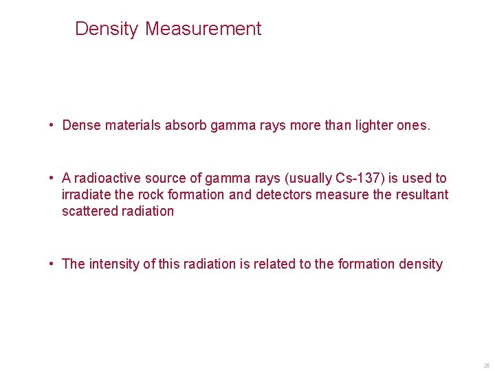
Density Measurement • Dense materials absorb gamma rays more than lighter ones. • A radioactive source of gamma rays (usually Cs-137) is used to irradiate the rock formation and detectors measure the resultant scattered radiation • The intensity of this radiation is related to the formation density 25
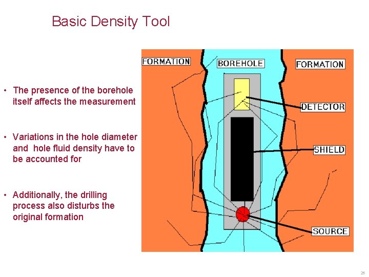
Basic Density Tool • The presence of the borehole itself affects the measurement • Variations in the hole diameter and hole fluid density have to be accounted for • Additionally, the drilling process also disturbs the original formation 26
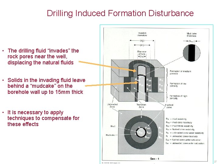
Drilling Induced Formation Disturbance • The drilling fluid “invades” the rock pores near the well, displacing the natural fluids • Solids in the invading fluid leave behind a “mudcake” on the borehole wall up to 15 mm thick • It is necessary to apply techniques to compensate for these effects 27
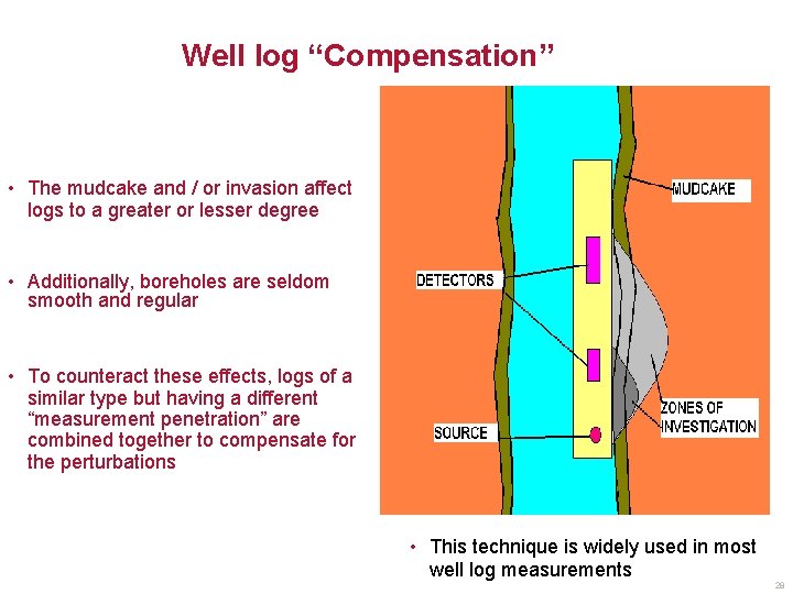
Well log “Compensation” • The mudcake and / or invasion affect logs to a greater or lesser degree • Additionally, boreholes are seldom smooth and regular • To counteract these effects, logs of a similar type but having a different “measurement penetration” are combined together to compensate for the perturbations • This technique is widely used in most well log measurements 28
Logging The Well a) Identify Rock Type e. g. Measure level and nature of natural radioactivity b) Measure Rock Porosity e. g. Measure bulk density using gamma ray transport (Porous rocks are less dense) Measure hydrogen density using neutron transport (Both water & oil contain hydrogen) c) Identify Pore Fluids e. g. measure electrical resistivty low resistivity = water high resistivity = hydrocarbon d) Measure Rock Mechanical Properties e. g. measure acoustic velocities 29
Neutron Porosity Measurement • Water and oil contain Hydrogen in about the same proportions. – Water = H 2 O, Oil = (H 2 C)Xn • The nucleus of a hydrogen atom is a single proton • Neutrons and protons are elementary particles making up an atomic nucleus. Neutrons have a similar mass to protons, and because they are un-charged, can approach, and interact with, positively charged atomic nuclei • A neutron has a much better chance of interacting with a particle of a similar mass to itself than with a heavier one – e. g 2 billiard balls, when colliding, interact, but a billiard ball does not interact much with a ping-pong ball • A radioactive source of fast neutrons is used to irradiate the rock formation and detectors measure the resultant neutron flux • The neutrons dominantly interact with the single proton of a hydrogen nucleus. • The resultant neutron population therefore reflects the amount of hydrogen present which, in turn, is a measure of the rock porosity 30
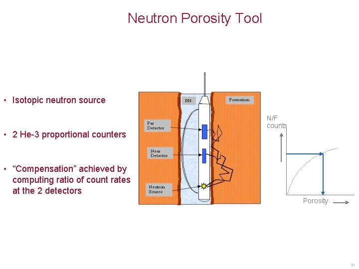
Neutron Porosity Tool • Isotopic neutron source • 2 He-3 proportional counters N/F counts • “Compensation” achieved by computing ratio of count rates at the 2 detectors Porosity 31
Interpretation And Calibration • It is important to remember that: – Density tools do not measure density • They measure gamma radiation intensity at point(s) in space – Neutron tools do not measure porosity • They measure neutron fluxes at point(s) in space. • Getting Density and Porosity is then a question of interpreting the measurement, assuming that it has been properly calibrated 32
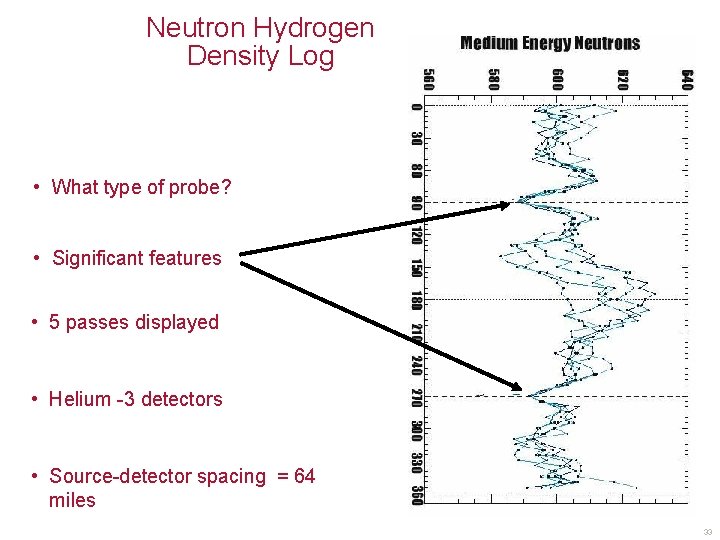
Neutron Hydrogen Density Log • What type of probe? • Significant features • 5 passes displayed • Helium -3 detectors • Source-detector spacing = 64 miles 33
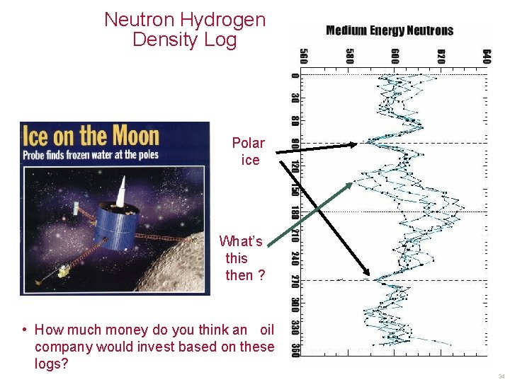
Neutron Hydrogen Density Log • Polar ice aaaaa • aaaa What’s this then ? • How much money do you think an oil company would invest based on these logs? 34
Response Calibration And Characterisation Using CALLISTO • CALibration at • CALLISTO a World-standard facility for the calibration and characterisation of (predominantly) nuclear well logging probes is • Leicester & • In - Situ • Tool Optimisation • EUROPA’s sister 35
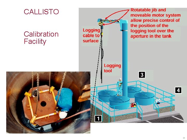
CALLISTO Calibration Facility 36
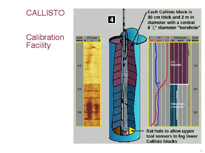
CALLISTO Calibration Facility 37
Logging The Well a) Identify Rock Type e. g. Measure level and nature of natural radioactivity b) Measure Rock Porosity e. g. Measure bulk density using gamma ray transport (Porous rocks are less dense) Measure hydrogen density using neutron transport (Both water & oil contain hydrogen) c) Identify Pore Fluids e. g. measure electrical resistivty low resistivity = water high resistivity = hydrocarbon d) Measure Rock Mechanical Properties e. g. measure acoustic velocities 38
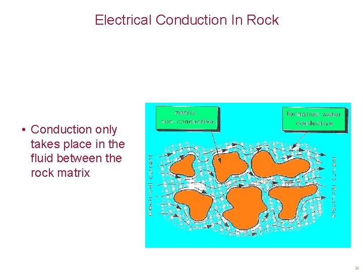
Electrical Conduction In Rock • Conduction only takes place in the fluid between the rock matrix 39
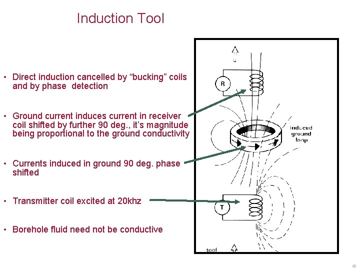
Induction Tool • Direct induction cancelled by “bucking” coils and by phase detection • Ground current induces current in receiver coil shifted by further 90 deg. , it’s magnitude being proportional to the ground conductivity • Currents induced in ground 90 deg. phase shifted • Transmitter coil excited at 20 khz • Borehole fluid need not be conductive 40
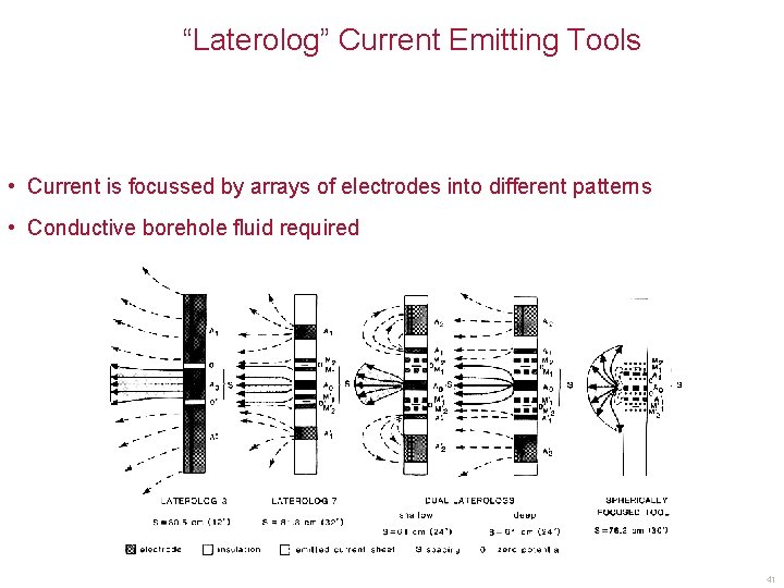
“Laterolog” Current Emitting Tools • Current is focussed by arrays of electrodes into different patterns • Conductive borehole fluid required 41
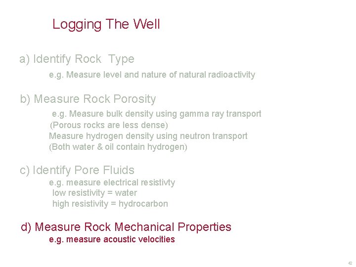
Logging The Well a) Identify Rock Type e. g. Measure level and nature of natural radioactivity b) Measure Rock Porosity e. g. Measure bulk density using gamma ray transport (Porous rocks are less dense) Measure hydrogen density using neutron transport (Both water & oil contain hydrogen) c) Identify Pore Fluids e. g. measure electrical resistivty low resistivity = water high resistivity = hydrocarbon d) Measure Rock Mechanical Properties e. g. measure acoustic velocities 42
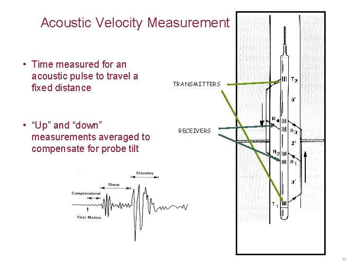
Acoustic Velocity Measurement • Time measured for an acoustic pulse to travel a fixed distance • “Up” and “down” measurements averaged to compensate for probe tilt TRANSMITTERS RECEIVERS 43
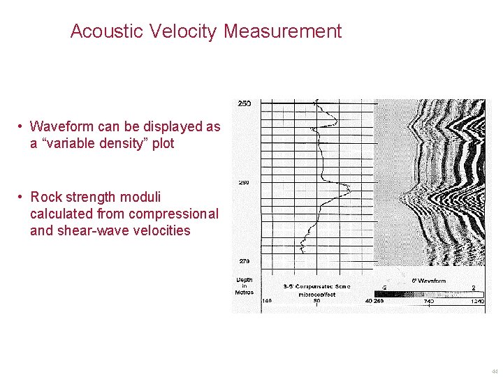
Acoustic Velocity Measurement • Waveform can be displayed as a “variable density” plot • Rock strength moduli calculated from compressional and shear-wave velocities 44
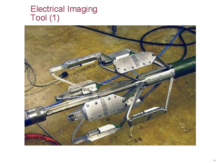
Electrical Imaging Tool (1) 45
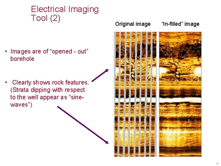
Electrical Imaging Tool (2) Original image “In-filled” image • Images are of “opened - out” borehole • Clearly shows rock features. (Strata dipping with respect to the well appear as “sinewaves”) 46
Application to Space Exploration • Seismology (“Echo sounding”) – Seismology can potentially reveal internal structure and dynamic processes of other rocky bodies—planets, moons, and asteroids— in the solar system, if seismic sensors can be deployed • Magnetometry – Magnetometers are used occasionally in well-logging, but are used extensively in space probes to investigate all sorts of magnetic properties and phenomena. • Gravimetry – Again, used occasionally in well logging to indicate density or mass anomalies, but used extensively in space probes 47
Application to Space Exploration • Neutron methods – Remember “The resultant neutron population therefore reflects the amount of hydrogen present which, in turn, is a measure of the rock porosity” – This can also indicate the presence of water, as we already discussed with respect to the Lunar orbiter albeit with a 64 mile source detector spacing! The neutron source in this case was the lunar surface itself, where neutrons were released by cosmic ray bombardment. • Neutron spectrometry – Neutron bombardment can also provoke the release of specific gamma-rays from which elemental composition can be determined 48
Application to Space Exploration • Density measurements – The Bepicolombo Mercury mission, launching this year, originally had a lander containing a mole with a density measurement. Cancelled due to cost. • Natural Radiation – Curiosity Martian rover contained a RAD detector to assess various sorts of natural radiation. 49
Conclusion • 45 -year career in Well-logging R&D (1972 -2017) • A large variety of techniques employed • Seen dramatic changes • From the perspective of 1972: • By 2000 there would have been no oil left. • We would now be running on a coal economy • No-one worried about global warming, in fact cooling was the concern if the Gulf Stream “turned off”. • The only computing power we had in 1972 was a 4 function calculator and that belonged to Accounts! 50
- Slides: 51