Geodetic Horizontal Control Techniques Hussein AbdElmotaal Professor of

Geodetic Horizontal Control Techniques Hussein Abd-Elmotaal Professor of Surveying and Geodesy Minia University Lecture Five

Well Conditioned Triangles of a Triangulation System • The arrangement of triangles in the layout and the magnitude of the angles in individual triangles, affect the accuracy of a triangulation system. • The shape of the triangle in which any error in angular measurements, has a minimum effect upon the lengths of the computed sides, is known as a well conditioned triangle. • Hence, the best shape of a triangle is an isosceles triangle whose base angles are 56° 14' each. • But, for all practical purposes, an equilateral triangle may be treated as a well conditioned triangle. • Note: The triangles, whose angles are less than 30° or more than 120°, should be avoided in the chain of triangles.

Station marks • Object of station marks is to provide a surface mark with a permanent mark buried below the surface on which a target or instruments is to centred over it • Should be bronze or copper marks cemented into rock or concrete surface • Control points can be constructed in concrete with centre mark in bronze or copper and buried at the required place • Few dead measurements are taken using permanent features around the station and keep as a diagram

Satellite Station • In order to secure well condition triangle or better intervisibility objects such as church tops, flag poles or towers etc. are sometime selected as triangulation stations • If the instruments is impossible to set up over that point a subsidiary station known as a satellite station or false station is selected as near as possible to the main station • Observations are made to the other stations with the same precision from the satellite station

Reduction to center • The angles are then corrected and reduced to what they would be from the true station • The operation applying to this correction due to the eccentricity of the station is generally known as reduction to centre • Distance between true station and satellite station is determined by method of trigonometric levelling

Signals • They are the devices erected to define the exact position of a station • A signal is placed at each station so that the line of sights are established between triangulation stations Classification of Signals (a) luminous signals (b) opaque signals. Luminous Signals: Luminous signals are further divided into two categories • sun signals • night signals.

Signals Sun Signals Night Signals • Those signals which reflect the rays of the sun towards the station of observation, are known as heliotropes. • Such signals can only be used in clear weather. • While making observations at night, night signals are used. • Various types of night signals are: Various forms of oil lamps with a reflector. These are used for sights less than 80 km. Acetylene lamps designed by captain G. T. Mc. Caw. These are used for sights more than 80 km.

Signals Opaque Signals • The opaque, or non-luminous signals used during day • Various forms and the ones most commonly used are the following Pole Signal Target Signal Pole and Brush Signals Stone Cairn Beacon Pole Signal • It consists of a round pole painted black and white in alternate and is supported vertically over the station mark on a tripod. • Pole signalsleare upsuitab to a distance f 6 km. o

Target Signal • It consists of a pole carrying two square or rectangular targets placed at right angles to each other • The targets are generally made of cloth stretched on wooden frames • Target signals are suitable up to a distance of 6 km

Pole and Brush Signals • It consists of a straight pole about 2· 5 meter long with a bunch of long grass tied symmetrically round the top making a cross • The signal is erected vertically over the station mark by heaping a pile of stones up to 1· 7 meters round the pole • A rough coat of white wash is applied to make it more conspicuous to be seen against a black back ground

Stone Cairn • It consists of stones built up to a height of 3 meters in a conical shape. • This white washed opaque signal is very useful if the back-ground is dark.

Beacon It consists of red and white cloth tied round the three straight poles. • This can be easily centered over the station marks • Beacons are useful when simultaneous observations are made at both the stations. •

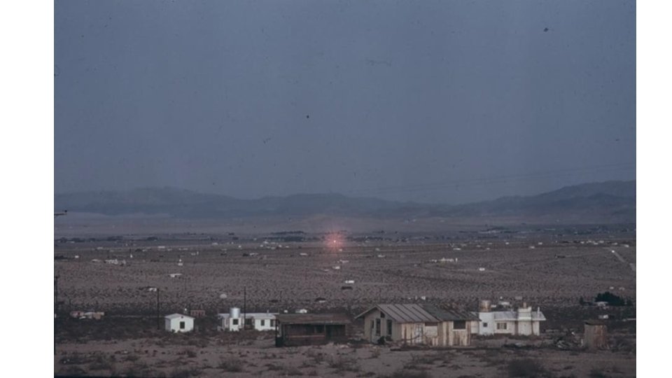
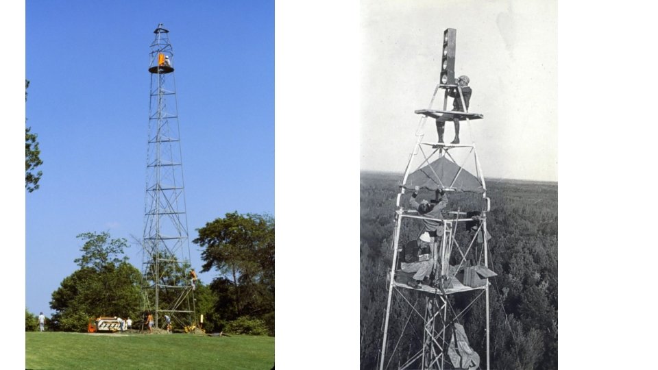
Towe • A tower is erected at the triangulation station when r the station or the signal or both are to be elevated to make indivisibility between station • Towers generally have two independent structures • Outer structure is for supporting the observer and the signal whereas the inner one is for supporting the instrument only • The two structures are made entirely independent of each other so that the movement of the observer does not disturb the instrument setting • Two towers may be made of masonry, timber or steel • Timber scaffolds are most commonly used, and have been constructed to heights over 50 m

Reconnaissanc e • Objective of the reconnaissance is to plan a system of triangulation in accordance with the specifications laid down for the type of triangulation • Reconnaissance team should prepare a well defined description of the stations selected by them due to two main reasons Observation team will identify the stations from this report Stations are to be used for decades • Description must include the approximate directions to the prominent topographic features. • Method of approach and the path to be followed to the station should also be included • Locations of water, camping sites and local food supplies can also be noted

Criteria for selection of triangulation • Triangulation stations must be selected carefully stations • It can save a lot of time and funds by keeping the following key points in mind Triangulation stations should be intervisible. Stations should be easily accessible with instruments. Station should form well-conditioned triangles. Stations should be located so that the survey lines are neither too small nor too long Cost of clearing and cutting and building towers should be minimum No line of sight should pass over the industrial areas to avoid irregular atmospheric refraction

Determination of intervisibility and height of triangulation stations • Intervisibility between stations is the most essential condition in triangulation • When the distance between stations is too large or the elevation difference is less both signal and station to be elevated to overcome the effect of the earth curvature • The calculations of height of signal and instrument depends upon the following factors Distance between the stations Relative elevation of the stations Profile of the intervening ground

Distance between the stations • If the intervening ground does not obstruct the intervisibility, the distance of horizon from the station of known elevation is given by the following formula

Relative elevation of the stations • Distance between two stations A and B of heights ℎ��and ℎ�� respectively is D. • �� are the distances of visible ��and �� �� horizon from A and B respectively and ′ required elevation at B above the ℎ�� datum • Since �� = �� − �� , ℎ′ �� can be �� �� calculated and checked whether to be raised above the ground. • Normally the line of sight is kept at 3 m above the ground as the refraction is maximum near the ground

Base Line • Field work for base line measurement is carried out by two groups as setting out group and measurements the measuring group • After the measurements the most probable length is calculated applying the following corrections Corrections for base line measurement Correction for the absolute length Correction for temperature Correction for pull or tension Correction for Sag Correction for slope Correction for alignment Reduction to mean sea level Axis signal correction Correction for the unequal height Reduction to Chord to arc
- Slides: 21