Genesee County Drain Commissioner Water and Waste Services


")


- Slides: 25
Genesee County Drain Commissioner Water and Waste Services Division District #3 Linden WWTP Digester Improvements Project, Phase I Joe Goergen, GCDC - WWS Tom Grant, HRC
INTRODUCTION n n Hubbell, Roth and Clark is assisting the Genesee County Drain Commissioner with improvements to the digesters at the Linden WWTP. The project includes: n Adding vortex mixing equipment to two anaerobic digesters n Sludge and gas piping improvements n Two new heat exchangers n Replacement of existing air actuated diaphragm pumps with new rotary lobe pumps.
FUNDING AND COSTS n n The approximate construction cost is $1. 3 Million, which is being funded with an MDNRE SRF loan and 40% ARRA principal forgiveness. Mr. Matt Raysin, P. E. , Division Engineer and Mr. Joe Goergen, Division Superintendent is overseeing the construction for the County. Also involved are Jeffrey Wright, Drain Commissioner, and John F. O’Brien, P. E. , Director of Water and Waste Services. Sorensen-Gross Construction Services is the General Contractor.
DISTRICT #3, LINDEN WWTP n n n Plant was originally constructed in 1963 and provides influent pumping, primary settling, secondary treatment (activated sludge) and settling, and UV disinfection prior to discharge into the Shiawassee River. Currently is rated for 11 MGD average flow and 16 MGD peak flow. Solids handling facilities consist of anaerobic digesters for primary sludge, sludge thickening via dissolved air flotation (DAF) for secondary sludge, sludge storage vaults, and a loading station for hauling sludge off-site for land application and or landfill.
BACKGROUND, PHASE I n Phase I Project Scope: n Digesters: n New vortex mixing n Sludge and gas piping improvements n Two new sludge-to-sludge heat exchangers n Sludge pump replacements n New instrumentation and controls
BACKGROUND, PHASE II n Phase II Project Scope: n Under consideration for increased energy efficiency and utilization without adding maintenance demands
DIGESTER MIXING n n The existing Primary Digester No. 1 gas mixing equipment did not efficiently mix the digester contents. The existing Primary Digester No. 2 was not equipped with any mixing. The new vortex liquid mixing system improves the digesters’ operational efficiency, resulting in increased volatile solids destruction and gas generation. The new system includes four jet nozzles and a 1, 500 gpm centrifugal chopper pump at each digester.
VORTEX MIXING SYSTEM n System selected was the Vaughan “Rotamix” n Multiple fixed nozzles allow effective mixing energy distribution without the need for rotating equipment. n Can mix tanks after long periods of storage, and allows intermittent operation, reducing energy costs n Chopper pumps reduce clogging problems due to fibrous material and other debris n System operates without liquid level dependency n No scheduled nozzle maintenance required, and no rotating equipment within the process.
VORTEX MIXING SYSTEM
VORTEX MIXING SYSTEM
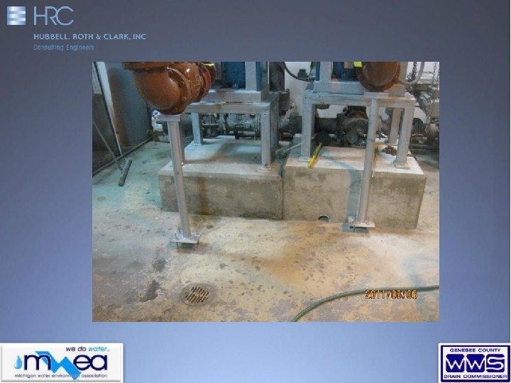
MIXING PUMP (CHOPPER)
TEMPERATURE MANAGEMENT n n The solids pumped from the Primary Clarifiers to the Digester No. 1 caused heat loss and occasional upsets due to the temperature differential. Two new spiral heat exchangers now pre-warm the solids for better efficiency. Solids from Digester No. 1 pass through the heat exchanger as they are pumped to Digester No. 2 to warm the primary solids from the clarifiers. A flow control valve is used to match the flow rates, keeping the level in Digester No. 1 tank constant.
SPIRAL HEAT EXCHANGERS n n Project included two Alfa-Laval Spiral Heat Exchangers, each 150 gpm Utilizes a single channel that allows for fully counter-current flow. Channels are curved with uniform cross-section that causes a spiraling motion within the fluid. The spiraling motion keeps the fluid fully turbulent, keeping solids in suspension and produces a “self-cleaning” action. Side cover opens to expose entire surface. Images from Alfa-Laval
HEAT EXCHANGERS
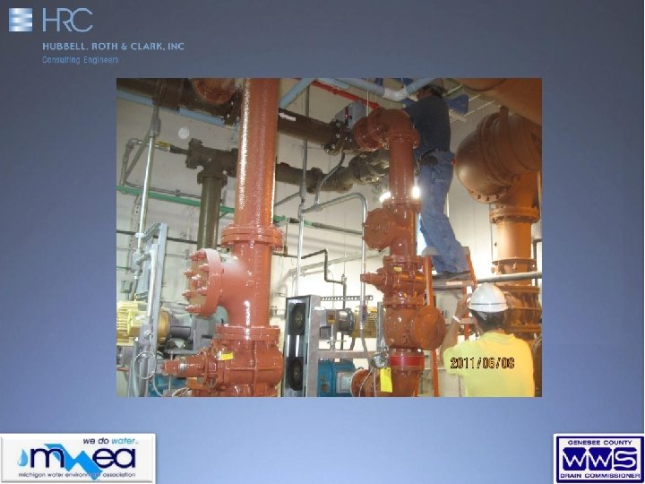
PUMP REPLACEMENT n n Existing air diaphragm and “plunger” pumps that were beyond useful life were replaced with rotary lobe pumps Variable Frequency Drives (VFDs) were also added to some pumps to allow for more efficient operation
PROJECT COORDINATION n Project required significant planning and support from Plant personnel to ensure the day-to-day operation would not be impacted by the construction.
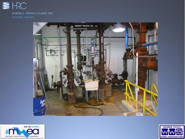
ADDITIONAL PHOTOS
ADDITIONAL PHOTOS
ADDITIONAL PHOTOS
ADDITIONAL PHOTOS
ADDITIONAL PHOTOS
n Thank you!!! n Questions? ? ?