General principles of Industrial Instrumentation Lecture 2 Measurements


 is")


 mechanical instruments, (ii) electrical instruments and (iii) electronic instruments.")


- Slides: 23
General principles of Industrial Instrumentation Lecture 2
Measurements • Measurements provide us with a means of describing various phenomena in quantitative terms. It has been quoted "whatever exists, exists in some amount". The determination of the amount is measurement all about.
METHODS OF MEASUREMENT • Direct Methods. • In-Direct Methods.
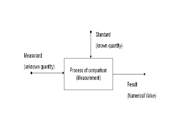
Direct Methods. • In these methods, the unknown quantity (also called the measurand) is directly compared against a standard. The result is expressed as a numerical number and a unit. Direct methods are quite common for the measurement of physical quantities like length, mass and time.
Indirect Methods • Measurements by direct methods are not always possible, feasible and practicable. • A measurement system consists of a transducing element which converts the quantity to be measured into an analogous signal. The analogous signal is then processed by some intermediate means and is then fed to the end devices which present the results of the measurement.
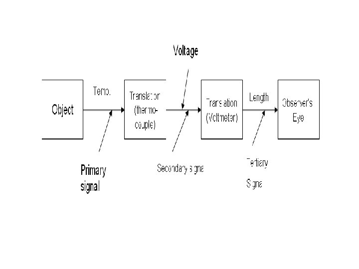
PRIMARY, SECONDARY AND TERTIARY MEASUREMENTS • Primary Measurements: - A primary measurement is one that can be made by direct observation without involving any conversion • Secondary Measurements: - A secondary measurement involves only one translation (conversion) to be done on the quantity under measurement
• Tertiary Measurements : -A tertiary measurement involves two translations Eg: Thermocouple
Instrumentation • Instrumentation is used in almost every industrial process and generating system, where consistent and reliable operations are required. • Instrumentation provides the means of monitoring, recording and controlling a process to maintain it at a desired state. • Because of the continuous interactive nature of most industrial process systems, manual control is nonfeasible and unreliable. With instrumentation, automatic control of such processes can be achieved.
• An instrument could be mounted at the process location to indicate the process state to the plant personnel. This form of data display is referred to as local or field indication • Hazardous condition • Representative signal • Field process state • automatic corrective action • alarm units
Types of instruments (i) mechanical instruments, (ii) electrical instruments and (iii) electronic instruments.
Mechanical Instruments. • These instruments are very reliable for static and stable conditions. • Have moving parts that are rigid, heavy and bulky • Potential source of noise and cause noise pollution. • Eg- Vernier gauge, Vibration meter, Tachometers
Electrical Instruments. • More rapid than mechanical methods. • Electrical system normally depends upon a mechanical meter movement as indicating device. This mechanical movement has some inertia and therefore these instruments have a limited time (and hence, frequency) response. • Eg: Analog Voltmeter , Ammeter etc.
Electronic Instruments • High speed response • Even very weak signals can be detected by amplifiers • Higher sensitivity • Greater flexibility, • Lower weight, • Lower power consumption and • Higher degree of reliability • Eg : Digital Multimeter.
• The two standard methods of transmitting a signal are: 1. Pneumatic 2. Electronic
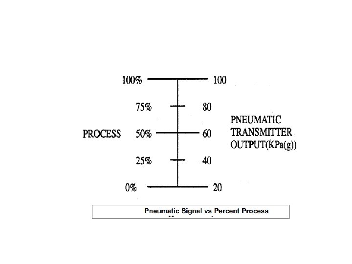
Pneumatic Signals • A pneumatic process sensor coupled to a transmitter is used to monitor a process variable; such as level in a tank or pressure in a pipe. • The output signal of the pneumatic transmitter is air pressure, the magnitude of which is directly proportional to the process variable being monitored. • The standard industrial range for pneumatic signals is 20 to 100 k. Pa(g) (k. Pa(g) = k. Pa above atmospheric), which corresponds to a 0% to 100% process condition.
Units of pressure
Advantages and Disadvantages of Pneumatic Transmission. • One advantage of a pneumatic system (over an electronic system) is that sparks will not be produced if a transmitter malfunction occurs, making it much safer when used in an explosive environment. • Furthermore, there is no electric shock hazard. • On the other hand, a pressurized system can be dangerous if a line ruptures. • Also, pneumatic signal lines are bulky and difficult to install • Time delay
Electronic Signals • For large industrial process applications such as generating stations where central control rooms are used, electronic signals are preferred and in many cases are used exclusively. • The process condition is monitored an electronic signal that is proportional to that process condition is produced by an electronic transmitter. • The accepted industrial standard for electronic signals is now a 4 to 20 m. A current signal that represents the 0% to 100% process condition. • Again, a live zero (4 m. A) is used to distinguish between 0% process (4 m. A) and an interrupted or faulted signal loop (0 m. A)
Electronic Signal Values vs Percent Process Measurement
Electronic Signals characteristics • When an electronic signal is used instead of a pneumatic signal the pressurized fluid transmission delay is eliminated. • The electronic current signals travel at speeds which approach the speed of light. • These current signals can be transmitted over long distances without the introduction of unnecessary time delays