Gears and Transmissions Why Is a Transmission Necessary


 gear /")


- Slides: 27
Gears and Transmissions
Why Is a Transmission Necessary? • Provide torque multiplication at low speeds • Reduce engine RPM at highway speeds • Allow the engine to operate within its most efficient RPM range • Allows the engine to be disengaged from the rear wheels while the vehicle is not moving (torque converter & clutch)
What Does a Transmission Do? • The basic purpose of a transmission breaks down into 3 parts – Ability to alter shaft RPM – Ability to multiply torque – Ability to reverse the direction of shaft rotation
How Does the Transmission Produce Torque Multiplication And/or RPM Reduction • Transmissions use gears – Spur – Helical – Planetary • Gears are able to change the RPM and the torque of the power moving through the transmission as well as the direction of rotation
• Spur – Simplest gear design – Straight cut teeth – Noisy operation Types of Gears • Helical – Spiral cut teeth – At least two teeth are in mesh at any time • Distributes the tooth load • Quieter operation • Planetary – Most complex design – Used in almost all automatic transmissions – Contains three parts • Sun gear • Planet gears • Internal gear (ring gear)
How Stuff Works Power Vs. Torque • Torque – measurement of twisting force • Power – measurement of how quickly work can be done – Power is dependent on torque and RPM – Horsepower = Torque x RPM 5252 Mustang Cobra VS. Caterpillar Diesel
How Stuff Works Gear Ratios • When two gears are in mesh, a gear ratio exists • Driven Gear = Ratio Drive Gear • Example: – – Drive gear has 14 teeth Driven gear has 28 teeth 28 14 = 2: 1 ratio (two to one ratio) The drive gear must rotate twice to make the driven gear rotate once
Reversal of Direction • When two gears are in mesh one will spin the opposite direction of the other • Idlers are used to reverse direction
Speed Change • The change in RPM from the input gear to the output gear is directly proportional to the gear ratio • Example: 3: 1 gear ratio – Input gear turns at 900 RPM – Output gear turns at 300 RPM
Torque Multiplication • The change in torque from the input gear to the output gear is directly proportional to the gear ratio • Example: 3: 1 gear ratio – Engine turns input gear at 900 RPM with 50 lb/ft of force – Output gear turns driveshaft at 300 RPM with 150 lb/ft of force
Torque Multiplication 1 inch 3 inches
Multiple Gear Ratios • Individual gear ratios can be multiplied to calculate a total gear ratio – Example: Chevy caprice with a TH-350 transmission and a 305 engine • By removing the differential cover and inspecting the gearset you are able to count 10 teeth on the input gear and 41 teeth on the output gear • 41 10 = 4. 1: 1 • You are able to find the 1 st gear ratio of the TH-350 in a manual which is listed as 2. 52: 1
Multiple Gear Ratios • Rear end ratio x 1 st gear ratio = total gear ratio • 4. 1 x 2. 52 = 10. 33: 1 – This tells us that the engine turns 10. 33 revolutions for every 1 revolution of the tires (speed reduction) • Torque multiplication can also be calculated – The 305 engine produces 245 lb/ft of torque at 3200 RPM – @ 3200 RPM in 1 st gear the torque acting on the rear tires = 230 lb/ft x 10. 33 = 2375. 9 lb/ft torque !!!
Gear Engine Output Torque Engine Speed Gear Ratio Transmission Output Torque Output Speed 1 200 ft/lbs 2000 RPM 4: 1 800 ft/lbs 500 RPM Underdrive 2 200 ft/lbs 2000 RPM 2: 1 400 ft/lbs 1000 RPM Underdrive 3 200 ft/lbs 2000 RPM 1: 1 200 ft/lbs 2000 RPM Direct Drive 4 200 ft/lbs 2000 RPM . 5: 1 100 ft/lbs 4000 RPM Overdrive
Automatic Transmission I. D. • Most automatics are identified by the oil pan. – Look at the shift indicator to determine if the transmission is a 3 -speed, 4 -speed etc. • Different transmissions may have been installed in otherwise identical vehicles. • Shopkey and other manuals list transmission application by vehicle.
Automatic Transmission I. D.
Automatic Transmission I. D. GM I. D. 1 Aluminum Powerglide 14 bolts 2 TH 200 Metric 11 bolts 3 TH 350 13 bolts 4 TH 400 13 bolts 5 TH 200 -4 R 16 bolts 6 TH 700 -R 4, 4 L 60 E 16 bolts 7 4 L 80 E 17 bolts
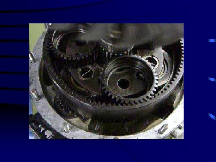
Planetary Gearsets • Simple planetary gearsets contain three components – Internal (ring) gear / (annulus gear) – Planet gears (and carrier) – Sun gear • One component will be the drive member, one the driven, and one will be held (except direct drive and neutral) • Unlike other types of gears, planetary gears are able to operate on one single axis
Planetary Action • Direct Drive – Any two of the components are driven – 1: 1 Ratio
Planetary Action • Underdrive – Planet carrier is the output • Minimum reduction – Ring gear is held – Sun gear is the input • Maximum reduction – Ring gear is input – Sun gear is held
Planetary Action • Overdrive – Planet carrier is the input • Minimum overdrive – Ring gear is the input – Sun gear is held • Maximum overdrive – Ring gear is held – Sun gear is the input
Planetary Action • Reverse – Planet carrier is held • Underdrive – Ring gear is the output – Sun gear is the input • Overdrive – Ring gear is the input – Sun gear is output
Sun Carrier Internal Speed Torque Direction Input Output Held Maximum Reduction Maximum Increase Same as Input Held Output Input Minimum Reduction Minimum Increase Same as Input Output Input Held Maximum Increase Maximum Reduction Same as Input Held Input Output Minimum Increase Minimum Reduction Same as Input Held Output Reduction Increase Opposite as Input Output Held Input Increase Reduction Opposite as Input
Calculating Planetary Gear Ratios • Direct Drive = 1: 1 • Underdrive – Carrier is output # of sun gear teeth + #of ring gear teeth = Ratio # of teeth on the driving member
Calculating Planetary Gear Ratios • Overdrive – Carrier is input # of teeth on the driven member. = Ratio # of sun gear teeth + #of ring gear teeth
Calculating Planetary Gear Ratios • Underdrive – Carrier is held # of teeth on driven gear # of teeth on driving gear = Ratio