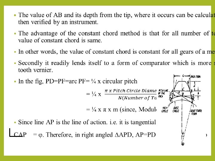
Gear tooth thickness Measurement by Constant Chord Method

Gear tooth thickness Measurement by Constant Chord Method: • In the Gear Tooth Vernier Caliper method, it is seen that both the chordal thickness and chordal addendum are dependent upon the number of teeth. • Hence for measuring a large number of gears for set, each having different number of teeth would involve separate calculations. Thus the procedure becomes laborious and time-consuming one. • The constant chord method does away with these difficulties. • Constant chord of a gear is measured where the tooth flanks touch the flanks of the basic rack. • The teeth of the rack are straight and inclined to their centre lines at the pressure angle as shown in Fig.

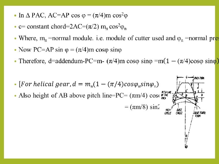
• Also the pitch line of the rack is tangential to the pitch circle of the gear and, by definition, the tooth thickness of the rack along this line is equal to the arc tooth thickness of the gear round its pitch circle. • Now, since the gear tooth and rack space are in contact in the symmetrical position at the points of contact of the flanks, the chord is constant at this position irrespective of the gear of the system in mesh with the rack. • This is the property utilised in the constant chord method of the gear measurement. • The measurement of tooth thickness at constant chord simplified the problem for all number of teeth. • If an involute tooth is considered symmetrically in close mesh with a basic rack form, then it will be observed that regardless of the number of teeth for a given size of tooth (same module), the contact always occurs at two fixed point A and B. • AB is known as constant chord. • The constant chord is defined as the chord joining those points, on opposite faces of the tooth, which make contact with the mating teeth when the centre line of the tooth lies on the line of the gear centres.
 Method: In")
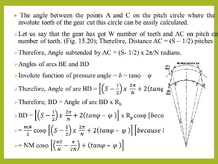
• Gear tooth thickness Measurement by base tangent(david brown tangent comparator) Method: In this method, the span of a convenient number of teeth is measured with the help of the tangent comparator. • This uses a single vernier calliper and has, therefore, the following advantages over gear tooth vernier which used two vernier scales : i. the measurements do not depend on two vernier readings, each being function of the other. ii. the measurement is not made with an edge of the measuring jaw with the face. ØConsider a straight generator (edge) ABC being rolled back and forth along a base circle (Fig. 15. 19). Fig. 15. 19. Generation of pair of involutes by a common generator.

Ø Its ends thus sweep out opposed involutes A 2 AA 1 and C 2 CC 1 respectively. ØThus the measurements made across these opposed involutes by span gauging will be constant (i. e. AC = A 1 C 1 = A 2 C 2 = A 0 C 0) and equal to the arc length of the base circle between the origins of involutes. ØFurther the position of the measuring faces is unimportant as long as they are parallel and on an opposed pair of the true involutes. ØAs the tooth form is most likely to conform to a true involute at the pitch point of the gear, it is always preferable to choose a number of teeth such that the measurement is made approximately at the pitch circle of the gear. ØThe value of the distance between two opposed involutes, or the dimension over parallel faces is equal to the distance round the base circle between the points where the corresponding tooth flanks cut i. e. , ABC in Fig. 15. 19. ØIt can be derived mathematically as follows :

Tangential Gear Tooth Calliper: q. It is utilised for measuring variations on the basic tooth profile from the outside diameter of spur and helical gears. q. The instrument consists of body, on the underside of which there are two slides having the tips acting like measuring contacts. q. The extended spindle of a dial indicator with the contact point A passes between the two tips along the vertical axis of symmetry of the instrument. q. The measuring tips are spread apart or brought together simultaneously and symmetrically in reference to the central axis by a screw which has a righthand a left-hand thread. q. The contact faces of the measuring tips are flat and arranged at angles of 14. 5° or 20° with the central axis. q. The calliper is set up by means of a cylindrical master gauge of proper diameter based on the module of the gear being checked. q. After nuts. adjusting the tips by the screw, these are locked in position by locking

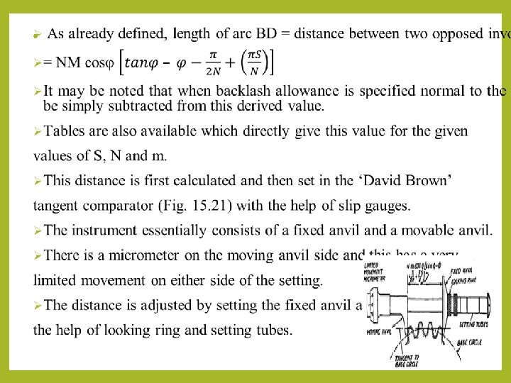
Measurement over Rolls or balls: v. A very good and convenient method is for measuring thickness of gear. In this method, two or three different size rollers are used to check the vibrations at different places on the tooth. 7. Measurement of concentricity v. In setting of gears, the centre about in which the gear is mounted should be coincident with the centre from which the gear is generated. v. It is easy to check the concentricity of the gear by mounting the gear between centres and measuring the variation in height of a roller placed between the successive teeth. v. Finally, the variation in reading will be a function of the eccentricity present. 8. Alignment checking v. It is done by placing a parallel bar between the gear teeth and the gear being mounted between centres. v. Finally, the readings are taken at the two ends of the bar and difference in reading is the misalignment.

Parkinson Gear Tester • The master gear is fixed on vertical spindle and the gear to be tested is fixed on similar spindle which is mounted on a carriage. • The carriage which can slide both side and these gears are maintained in mesh by spring pressure. • When the gears are rotated, the movement of sliding carriage is indicated by a dial indicator and these variations are the measure of any irregularities in the gear under test. • The variation's recorded in a recorder which is fitted in the form of a waxed circular chart. • In fig, the gears are fitted on the mandrels and are free to rotate without clearance. • Left mandrel moves along the table and the right mandrel moves along the spring-loaded carriage. • The two spindles can be adjusted so that the axial distance is equal and a scale is attached to one side and vernier to the other, this enables center distance to be measured to with in 0. 025 mm.

• If errors occur in the tooth form when gears will be in closer mesh, pitch or concentricity of pitch line will cause a variation in center distance from this movement of carriage as indicated to the dial gauge will show the errors in the gear test. • The recorder is also fitted in the form of circular or rectangular chart and the errors are recorded. Limitations of Parkinson gear tester: 1. Accuracy ± 0. 001 mm 2. Maximum gear diameter is 300 mm 3. Errors are not clearly identified. 4. Measurement is dependent upon the master gear. 5. Low friction in the movement of the floating carriage.

principle OF OPERATION OF A ROLLING GEAR TESTING MACHINE • When the master gear and gear under test are in closer mesh and rotated, any error will cause variation in center distance. • The movement of carriage is indicated on the dial gauge shown as the error in the gauge.

SURFACE FINISH measurement: • When we are producing components by various methods of manufacturing process, it is not possible to produce perfectly smooth surface and some irregularities are formed. • These irregularities cause some serious difficulties when using the components. • So, it is very important to correct the surfaces before use. • The factors which are affecting surface roughness are 1. Workpiece Material 2. Vibrations 3. Machining type 4. Tools and fixtures

Types of Surface Finish: Surface of a body is its boundary which separates it from another body. Generally there are two types of surfaces namely: Nominal Surface: A theoretically geometrically perfect surface is called as a nominal surface. Rough Surface: A magnified view of an actual surface is shown. This surface has numerous small peaks and valleys that deviate from the nominal surface. It is seen that the surface has a certain degree of roughness and hence it is called a rough surface. Rough Peak in the figure is called Wavy Surface: A surface having waviness as shown Surface N wavy surface. S Nominal Surface(NS) Valley

• The geometrical irregularities can be classified as 1. First order 2. Second order 3. Third order 4. Fourth order First order irregularities: They are caused by lack of straightness of guideways on which tool must move. Second order irregularities: They are caused by vibrations. Third order irregularities: They are caused by machining. Fourth order irregularities: They are caused by improper handling machines and equipments.

• Elements of Surface Texture: 1. Surface Roughness: It is the micro-irregularities in a surface resulting from the action of production process. 2. Profile: It is the shape of any section through a surface. 3. Flaw: It is an irregularity that occurs in a surface due to cracks, blow holes, scratches, etc. , Unless otherwise specified, the effect of flaws should not be accounted in the measurement of roughness. 4. Sample or Cut-off length: The particular length that is taken for sample measurement on the surface is called as cut of length. It is also known as roughness width cut off. 5. Lay: It is the direction of the predominant top surface grooves that are produced by machining. 6. Waviness: Surface irregularities that are of greater spacing than roughness.
 from which surface finish in numerical")
Datum for SURFACE FINISH measurement: • The datum(reference) from which surface finish in numerical values may be specified can be done in two methods namely The M System(The mean line system): a) üThe mean line or centre line is a line that is parallel to the general direction of the profile and is placed such that areas around the profile(above and below the line) are equal. B Areas X C A A Areas Y üMean üA B L line is determined as follows: straight line AA is drawn so that it is parallel to the general direction of the profile for a length L.

• Area above Area below L Locus of the center of circle of radius R R Curve brought down by distance R(Envelope curve) Mean envelope curve

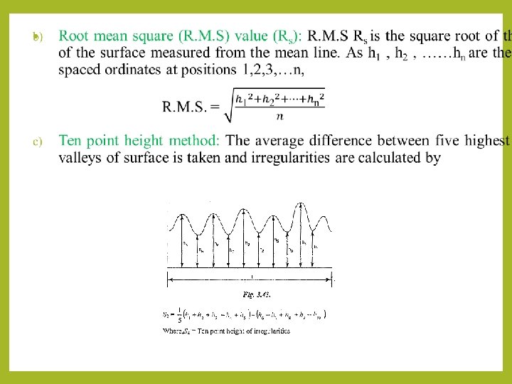
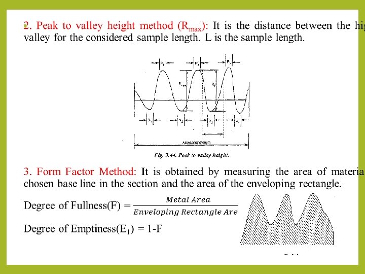
üNow the envelope curve is moved downwards to a position so that the areas around the surface profile(above and below the curve) are equal. üThis mean envelope curve becomes the mean line in the E system. Analysis of surface finish: The analysis of surface finish is being carried out by 1. The average roughness method. 2. Peak to valley height method 3. From factor 1. Average roughness measurement: The assessment of average roughness is carried out by a) Centre line average (CLA) value (Ra). b) Root mean square (RMS) value (Rs). c) Ten point method
 Centre line average (CLA) value (Ra): Ra is the average height from a")
a) Centre line average (CLA) value (Ra): Ra is the average height from a mean line of all ordinates of the surface, regardless of sign. Let h, h, …. , h be the height of the equally spaced ordinates at positions 1, 2, …n. n Another way of calculating Ra is shown in the figure.
: It is the distance between the mean line and")
4. The depth of Smoothness(Ru): It is the distance between the mean line and another line that is parallel to it drawn such that it touches the highest peak within the considered sampling length. Highest Peak Ru Mean Line Sampling Length (L) 5. The Mean Depth (Rm): It is the distance between the mean line and another line that is parallel to it drawn such that it touches the lowest valley within the considered sampling length. Mean Line Rm Sampling Length (L) Lowest Valley

Methods of SURFACE FINISH measurement: ü There are basically two methods for measuring surface finish, namely 1. Comparative or Qualitative Methods 2. Direct Measurement or Quantitative Methods q. Comparative or Qualitative Methods: In these methods, the surface texture is assessed by observation of the surface. The surface to be tested is compared with known value of roughness specimen and finished by similar machining process. The various methods which are used for comparison are 1. Touch Inspection. 2. Visual Inspection. 3. Microscopic Inspection. 4. Scratch Inspection. 5. Micro Interferometer. 6. Surface photographs. 7. Reflected Light Intensity. 8. Wallace surface Dynamometer.

üTouch Inspection: It is used when surface roughness is very high and the fingertip is moved along the surface at a speed of 2 Smmlsecond and the irregularities as up to 0. 0 125 mm can be detected in this method. üVisual Inspection: In this method, the surface is inspected by naked eye and this measurement is limited to rough surfaces. ü Microscopic Inspection: In this method, a finished surface is placed under the microscope and compared with the surface under inspection. The light beam is also used to check the finished surface by projecting the light about 60 C to the work.

üScratch Inspection: The materials like lead, plastics rubbed on surface are inspected by this method. The impression of this scratches on the surface produced is then visualized. üMicro-Interferometer: Optical flat is placed on the surface to be inspected and illuminated by a monochromatic source of light. üSurface Photographs: Magnified photographs of the surface are taken with different types of illumination. The defects like irregularities appear as dark spots and flat portion of the surface appears as bright. üReflected light Intensity: A beam of light is projected on the surface to be inspected and the light intensity variation on the surface is measured by a photo cell and this measured value is calibrated.

üWallace surface Dynamometer: It consists of a pendulum in which the testing shoes are clamped to a bearing surface and a predetermined spring pressure can be applied and then, the pendulum is lifted to its initial starting position. q. Direct Measurement or Quantitative Methods: Some of the direct measuring instruments are 1. Stylus probe instruments 2. Tomlinson surface meter 3. Profilometer 4. Taylor-Hobson Talysurf. v. Stylus probe instrument: Principle: When the stylus is moved over the surface to be measured, the irregularities in the surface texture are measured and it is used to assess the surface finish of the workpiece. Working: The stylus type instruments consist of skid, stylus, amplifying device and recording device. The skid is slowly moved over the surface

When the stylus moves vertically up and down, the stylus movements are magnified, amplified and recorded to get a trace. Then the trace is analysed by an automatic device. Advantage: 1. Any desired roughness parameter can be recorded. Disadvantages: 1. Fragile material cannot be measured. 2. High Initial cost. 3. Skilled operators are needed to operate.

v. Tomlinson Surface meter: Principle: This instrument uses mechanical-cum-optical means for magnification. Construction: In this, the diamond stylus on the surface finish recorder is held by spring pressure against the surface of a lapped cylinder. The lapped cylinder is supported one side by probe and other side by rollers. The stylus is also attached to the body of the instrument by a leaf spring and its height is adjustable to enable the diamond to be positioned and the light spring steel arm is attached to the lapped cylinder.

The spring arm has a diamond scriber at the end and smoked glass is rest on the arm. Working: When measuring surface finish, the body of the instrument moves across the surface by a screw rotation. The vertical movement of the probe caused by the surface irregularities makes the horizontal lapped cylinder to roll. This rolling of lapped cylinder causes the movement of the arm, So, this movement induces the diamond scriber on smoked glass. Finally, the movement of scriber together with horizontal movement produces a trace on the smoked glass plate and this trace is magnified by an optical projector. v. Profilometer: It is an indicating and recording instrument to measure roughness in microns. The main parts of the instrument are tracer and an amplifier.

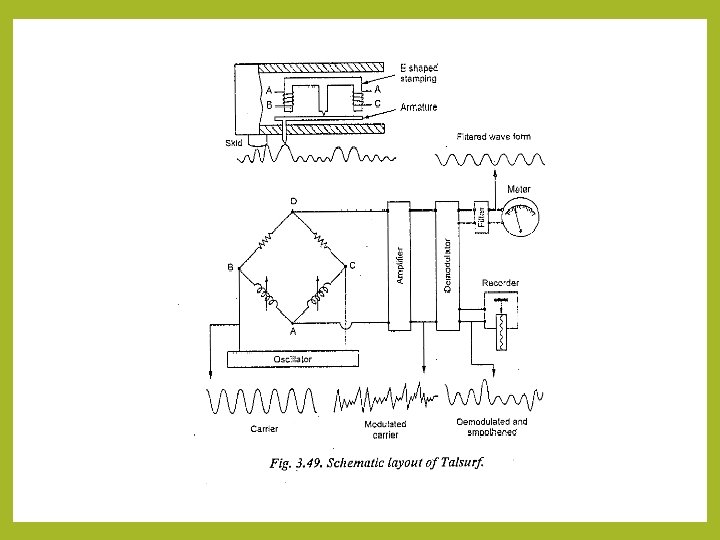
The stylus is mounted in the pick up and it consists of induction coil located in the magnet. When the stylus is moved on the surface to be tested, it will be displaced up and down due to irregularities in the surface. This movement induces the induction coil to move in the direction of permanent magnet and produces a voltage. This is amplified and recorded. v. Talyor-Hobson-Talysurf: It is working by carrier modulating principle and it is an accurate method comparing with the other methods. The main parts of this instrument are diamond stylus (0. 002 mm radius) and skid. Principle: The irregularities of surface are traced by the stylus and the movement of stylus is converted into changes in electric current. Working: On two legs of the E-shaped stamping, there are coils for carrying an A. C. current and these coils form an oscillator. As the armature is pivoted about the central leg, the movement of the stylus causes the air gap to vary and thus the amplitude is modulated. This modulation is again demodulated for the vertical displacement of the stylus. So, this demodulated output actuates or induces the pen recorder to produce a numerical record and to make a direct numerical assessment.

Other Methods for Measuring Surface Roughness: q. Profilograph: The surface finish to be checked is placed on the table. The table can move either side by lead screw and the stylus is pivoted over the tested surface. So, the oscillation in the stylus due to surface irregularities is transmitted to the mirror. A light source sends a beam of light through lens and a precision slit to the mirror, and the reflected beam is directed to revolving drum. A sensitive film is attached upon the revolving drum. The revolving drum can be rotated by two bevel gears and the gears are attached to the same lead screw. Finally, the profilogram will be obtained from the sensitive

q. Double microscope: It is an optical method for measuring the surface roughness. When a thin film of light strikes the surface to be tested by an angle of 45° through the condenser and precision slit and the observing microscope is also inclined at an angle of 45° to the tested surface. The surface is illuminated by a projection tube and it is observed by an eyepiece through the microscope. The eyepiece contains a eyepiece micrometre and it is used to measure the irregularities.

Straightness measurement: • Straightness is a geometrical shape. Geometrical tolerance for straightness will be specified if straightness is to be attained while manufacturing. • A line is said to be straight over a given length if the line is contained between two imaginary line that are placed at equidistance from the geometrically ideal position of the line being tested for straightness. Geometric Straightness The distance between the two imaginary lines tolerance for is to be equal to the error(e) specified straightness tolerance. straightness Geometrically Ideal Line Imaginary Lines Actual line being tested for straightness Lowest point on Highest point on actual Line

• Straightness error of a line is defined as the distance ‘e’ between two lines drawn parallel to the geometrically ideal line such that one of the two lines passes through the highest point on the actual line and the other line passes through the lowest point on the actual line. Straightness Measuring Instruments: • Following are the instruments used for measuring straightness namely, 1. Straight Edge 2. Spirit Level 3. Autocollimator q. Straight Edge: üA straight edge is a flat length of tool steel(or stainless steel) that is ground to extremely fine tolerance along its edges. üStraight edges are available from 30 cm to 360 cm. Straight edges are used to check surface for straightness. They are also used to scribe accurate straight lines.

üMethod-I: q. The simplest way of using a straight edge is to place the straight edge on the surface to be tested and determining the degree of contact by marking, feelers or light gap. Suppose light is used. The gap between the straight edge and surface will be negligible for perfectly straight surfaces. Straightness is measured by observing the colour of light by diffraction while passing through the small gap. Ex: If colour of light is red, it indicates certain gap in mm. üMethod-II: q. A straight edge is supported at two points for minimum deflection on two unequal piles of slip gauges such that it is at a slight inclination to the surface to be tested. q. Now divide the distance between the supports into number of equal parts and mark them on the straight edge. If the surface and straight edge are perfectly straight, the gap at each point will also vary uniformly. If the slip gauges used have values 5 mm and 5. 1 mm as shown in figure and if the distance between the slip values are divided into 5 equal parts, then the gap at each point will vary by 0. 02 mm(i. e. , 0. 1/5). Hence the value of pile of slip gauges required at position are:
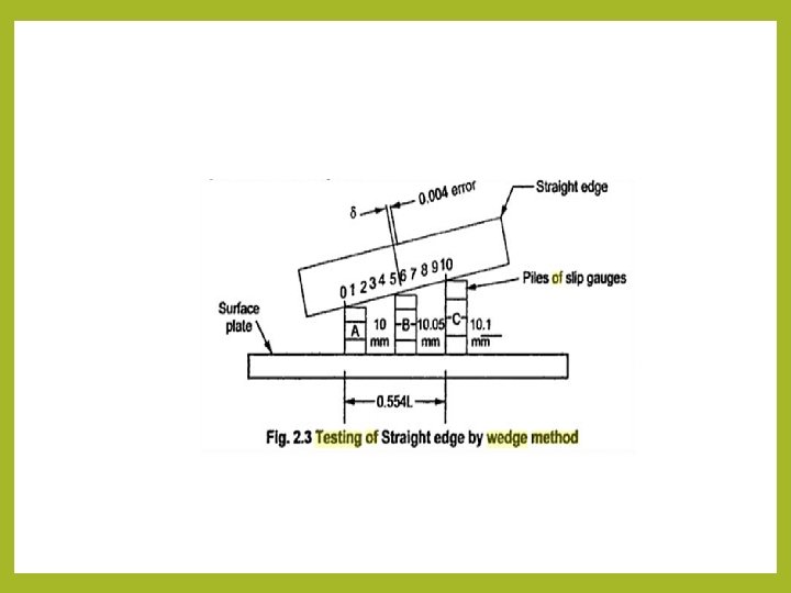

q. Position 3 = 5. 04 mm and so on, q. Now when the slip gauges are inserted at the marked positions, one of the following two condition occur. q[If slips make exact contact with both the surface at the marked position] => [There is no error in straightness] q[If slips don’t fit exactly at the marked position] => [There is error in straightness and is displayed along the straight edge by amounts proportional to the errors] q. Spirit Level: • The straightness of a surface to any length can be tested using a spirit level. This method has a high degree of accuracy. • The spirit level measures small angular displacements relative to a horizontal datum, the level of liquid at rest. • Straightness is checked using a spirit level as follows. A straight line(datum) is drawn on the surface whose straightness is to be checked. A spirit level with two feet(resting on the line) is moved along this line in steps. For each position the reading is noted. Variation in bubble

• Care should be taken to see that the spirit level is moved such that the length of each section is equal to the distance between center lines of the two feet. • Spirit level can be used only for the measurement of straightness of horizontal surfaces. They can’t be used on vertical surfaces. q. Auto Collimator: • The straightness of a surface of any length can be tested using an auto collimator. This method has a high degree of accuracy. • Auto collimator can be used on vertical side of horizontal slideways. • Auto collimator has a converging lens with a point source of light at its principal focus.

• When a parallel beam of light is projected from the lens and if a plane reflector is kept at 90 to the beam of light, the light will be reflected back along its own path and will be brought to focus at the same position as that of the light source. • If the reflector is tilted by an angle θ, the parallel beam of light will be deflected by twice the angle and will be brought to focus in the same plane as the light source but to one side of it. The image and object will not coincide, but will be placed at a distance of 2 fθ between them, f being the focal length of the lens. • This method of testing straightness consists of placing a block fitted with feet at convenient distance apart and carries a plane reflector. This arrangement is moved along the line to be tested for straightness in equal steps. Angular variation at each position is noted and is used to plot the graph of error. Cumulative Error Distance along surface tested

flatness measurement: • A surface is said to be flat within a given range of measurement when the variation of the perpendicular distance of its points from a geometrically ideal plane that is parallel to the trajectory of the surface to be tested remain below a given value. • The geometrically ideal plane can be represented by means of a surface plane or by a group of straight lines that are obtained by the displacement of a straight edge or a spirit level or a light beam. • Let us assume that the flatness tolerance is specified as 0. 08 mm. The tolerance value 0. 08 mm means that the surface being tested should be contained between two parallel planes which are 0. 08 mm apart. Flatness Testing: One way of testing flatness is to compare the surface with an accurate surface(geometrically ideal surface). If the test surface is small in size, then it is rubbed against an accurate surface that is evenly covered with Prussian blue colour paste. The distribution of colour over the test surface gives an idea of the peaks and valleys on the surface. If the test surface is large, then it is tested for flatness using a spirit level

• Procedure to determine flatness: üA surface can be considered to be a collection of a large number of lines. If all these lines are straight and lie on the same plane, the surface is said to be flat. üConsider a rectangular table as shown in the figure. All the generators/lines are straight and parallel to the sides of the rectangle in both the perpendicular directions. üFor a surface to be truly flat, the diagonal lines should also have straightness. üHence, the surface is divided by straight lines as shown. Lines are drawn little inside to take care of edge wearout. üThe straightness of all the lines(AB, BC, CD, DA, . . ) are determined. Then the lines are related

with each other to find out whether all of them lie on the same plane or not. Care is to be taken to see that when a spirit level or collimator reflector stand is used, one of its contact points of the feet of the block should lie on the center of the diagonals(I). üOnce the straightness of all the lines are determined, the readings are tabulated. ABD is considered to be an arbitrary plane. Hence the end points A, B and D are set to zero height. üNow height of point I is found with reference to plane ABD. Next point C is fixed with reference to the arbitrary plane ABD and then points, of lines BC and DC are corrected. As positions H, G, E and F are known, lines HG and EF are fitted. üIn this way the height of all the points on the test surface are determined relative to the arbitrary plane. • Flatness testing by Interferometry: üHere a monochromatic light source and a set of optical flats are used. üWhen an optical flat is placed on another reflecting surface whose flatness is to be determined, the optical flat will not form an intimate

• Now the optical flat is illuminated by monochromatic source of light. If the eye is placed in proper position, it will observe a number of bands. These bands are produced by the interference of light rays reflected from the bottom surface of the optical flat and the top surface of the test surface, through the thin layer of air between the surfaces. • At point A, the wave of incident beam from S is partially reflected along AB and is partially transmitted across air gap AC. At point C, the ray is reflected again along CD and extends along point E. Thus, the two reflected components have a travelled path whose lengths differ by an amount ACD. • If the path lengths of the two components differ by an odd number of half wave lengths, complete interference is achieved and a straight dark

• For all rays with path difference of odd number of half wave lengths, interference will occur and a similar dark fringe will occur(Ex: path FHI at H). • At intermediate points between point C and H, the path difference is an even number of half wavelength. As the two components are in phase, a light band is produced. • Thus alternate light and dark straight line bands are produced. A deviation from this pattern becomes a measure of error in flatness of the test surface.
 • By definition, roundness or circularity is the radial uniformity of")
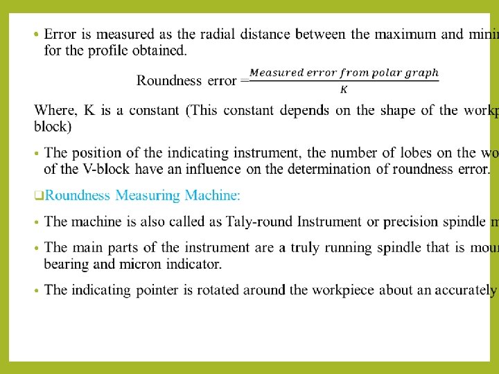
roundness measurement (Circularity) • By definition, roundness or circularity is the radial uniformity of work surface measured from the center line of the workpiece. • Circularity is specified by circularity tolerance. For example, if it is specified that circularity of a feature is to be 0. 1 mm, than it means that the circumference of each cross section of the feature should be contained between two coplanar concentric circles that are 0. 1 mm apart. • Error in roundness is defined as the radial distance between the minimum inscribing circle and maximum inscribing circle, that contain the actual profile of the surface at a section perpendicular to the axis of

• Methods for Measuring Roundness: • The important methods for measuring roundness are listed: a) V-block and dial indicator method b) Roundness Measuring Machine q. V-block and dial indicator method: • The arrangement consists of a V-block that is placed on the surface plate. The workpiece to be tested is placed in the V-groove of the Vblock as shown in the figure. • The feeler of a sensitive dial indicator (held firmly by a stand) is made to rest on the workpiece.

• Now the workpiece is rotated about the diameter to be checked. The dial indicator will indicate variations in the dimensions caused due to out of roundness. [Note: Lobbing: The diameters at any two opposite points are constant, but still it is not in circular form] • Plotting a Polar Graph: An idea of the actual shape of the workpiece can be obtained by plotting a polar graph. 12 equispaced markings at an angle of 30 are made in the face of the workpiece to be measured. The workpiece is placed on the V-block. The dial indicator is made to touch the workpiece at its center. Now when the workpiece is rotated and when the marking comes exactly under the plunger of the dial indicator, the reading is noted. Hence 12 readings will be obtained. The procedure is repeated thrice to get average values for each marking. Now for plotting the polar graph, a proper scale is selected. A circle of diameter equal to four times the maximum reading of the dial indicator is drawn. Another concentric circle is drawn in this circle. The values of the dial indicator are plotted in radial direction by taking the smallest circle as the reference circle. The individual points are joined by straight lines to get the actual profile of the workpiece. •

• The indicator shows deviations from roundness. As the output of the indicator is connected to an amplifier unit and pen recorder, a polar graph of the out line of the workpiece is obtained. • This is an accurate method. Automatic recording of the exact profile of the workpiece is obtained. Waviness also is superimposed on the profile of the workpiece.
- Slides: 53