GD T Chapter 2 Symbols Terms and Rules

GD & T Chapter 2 Symbols , Terms and Rules

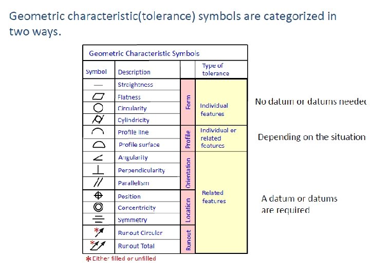
Chapter objectives • List the 14 geometric characteristic symbols • Identify the datum feature symbol • Explain the elements of the feature control frame • List the material condition modifiers • Identify the other symbols used with GD&T • Define critical terms • Explain general rules.

GD&T • GD&T is a means of dimensioning & tolerancing a drawing which considers the function of the part and how this part functions with related parts. – This allows a drawing to contain a more defined feature more accurately, without increasing tolerances.

GD&T • GD&T has increased in practice in last 15 years because of ISO 9000. – ISO 9000 requires not only that something be required, but how it is to be controlled. For example, how round does a round feature have to be? • GD&T is a system that uses standard symbols to indicate tolerances that are based on the feature’s geometry. – Sometimes called feature based dimensioning & tolerancing or true position dimensioning & tolerancing • GD&T practices are specified in ANSI Y 14. 5 M-1994.

For Example • Given Table Height Assume all 4 legs will be cut to length at the same time. • However, all surfaces have a degree of waviness, or smoothness. For example, the surface of a 2 x 4 is much wavier (rough) than the surface of a piece of glass. – As the table height is dimensioned, the following table would pass inspection. or • If top must be flatter, you could tighten the tolerance to ± 1/32 @ 0. 03. – However, now the height is restricted to 26. 97 to 27. 03 meaning good tables would be rejected.

Example cont’d. • You can have both, by using GD&T. – The table height may any height between 26 and 28 inches. – The table top must be flat within 1/16. (± 1/32). 06 28 26 . 06 27

Why GD&T important? • Saves money – For example, if large number of parts are being made – GD&T can reduce or eliminate inspection of some features. – Provides “bonus” tolerance • Ensures design, dimension, and tolerance requirements as they relate to the actual function • Ensures interchangeability of mating parts at the assembly • Provides uniformity • It is a universal understanding of the symbols instead of words
 Least Material")
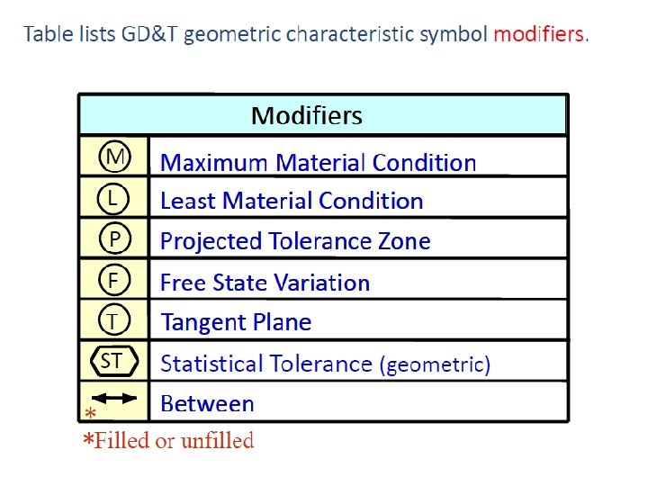
TERMINOLOGY REVIEW 1. 2. 3. 4. 5. 6. Maximum Material Condition (MMC) Least Material Condition (LMC) Tolerance Allowance Fit Basic Dimension
 Least Material")
TERMINOLOGY REVIEW 1. 2. 3. 4. 5. 6. Maximum Material Condition (MMC) Least Material Condition (LMC) Tolerance Allowance Fit Basic Dimension
 M Maximum Material Condition (MMC) a condition in which the")
1. MMC(Maximum material condition) M Maximum Material Condition (MMC) a condition in which the feature contains the maximum amount of material relative to the associated tolerances. Examples are maximum shaft diameter and minimum hole diameter. Examples: • Largest pin diameter (Largest shaft) • Smallest hole size. (smallest hole)
 Least Material Condition (LMC) is a condition which the")
2. LMC (Least Material Condition) Least Material Condition (LMC) is a condition which the feature contains the least amount of material relative to the associated tolerances. Examples are maximum hole diameter and minimum shaft diameter. Examples: • Smallest pin diameter (smallest shaft) • Largest hole size (largest hole) L

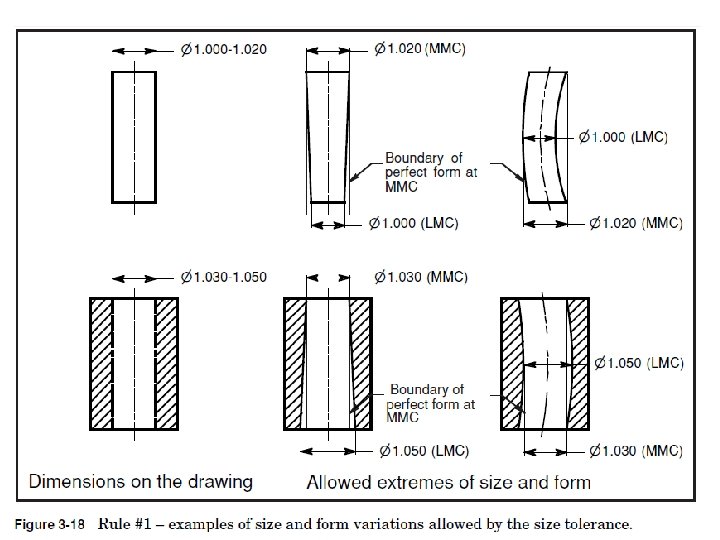
Limit of size • A variation in form is allowed between the least material condition (LMC) and the maximum material condition (MMC). Envelop Principle defines the size and form relationships between mating parts.

Limit of size ENVELOPE PRINCIPLE LMC CLEARANCE MMC ALLOWANCE

Limit of size The actual size of the feature at any cross section must be within the size boundary.

Limit of size No portion of the feature may be outside a perfect form barrier at maximum material condition (MMC).

3. Clearance is defined as the loosest fit or maximum intended difference between mating parts. The calculation formula for clearance is: CLEARANCE = LMC HOLE – LMC SHAFT (largest hole – smallest shaft)
 limits")
4. Allowance is defined as an intentional difference between the maximum material (MMC) limits of mating parts. Allowance is the minimum clearance (positive allowance), or maximum interference (negative allowance) between mating parts. Calculation formula is ALLOWANCE = MMC HOLE – MMC SHAFT (smallest hole – biggest shaft)

5. Fit • Fit is generally term used to signify the range of tightness or looseness which may result from the application of a specific combination of allowance and tolerance in the design of mating part features. • Fits are of generally three types: a. Clearance fit b. Interference fit c. Transition fit

a. Clearance Fit • The parts are toleranced such that the largest shaft is smaller than the smallest hole. • The allowance is positive and greater than zero. • In here allowance > 0 • Ex-Clutches, Bearing covers, Oil seals with metal housing.

b. Interference Fit • Considerable pressure is required to assemble these fits and the parts are considered more or less permanently assembled. • In here allowance =0 • Examples-gear wheels, couplings, valve seats.

c. Transition Fit • The parts are toleranced such that the allowance is negative and the max. • In here allowance <0 • Examples-belt pulleys, bushes, fit bolts.

Sample Calculation Find MMC, LMC, allowance, clearance and determine type of fit

Given: MMC of hole=dia 1. 2500 MMC of shaft=dia 1. 2509 LMC of hole=dia 1. 2506 LMC of shaft=dia 1. 2503 Allowance=MMC hole-MMC shaft 1. 2500 -1. 2509= -0. 0009 Clearance=LMC hole-LMC shaft 1. 2506 -1. 2503= 0. 0003 Allowance= -0. 0009 Clearance= 0. 0003 Type of fit= Transition fit

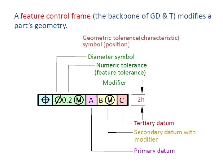
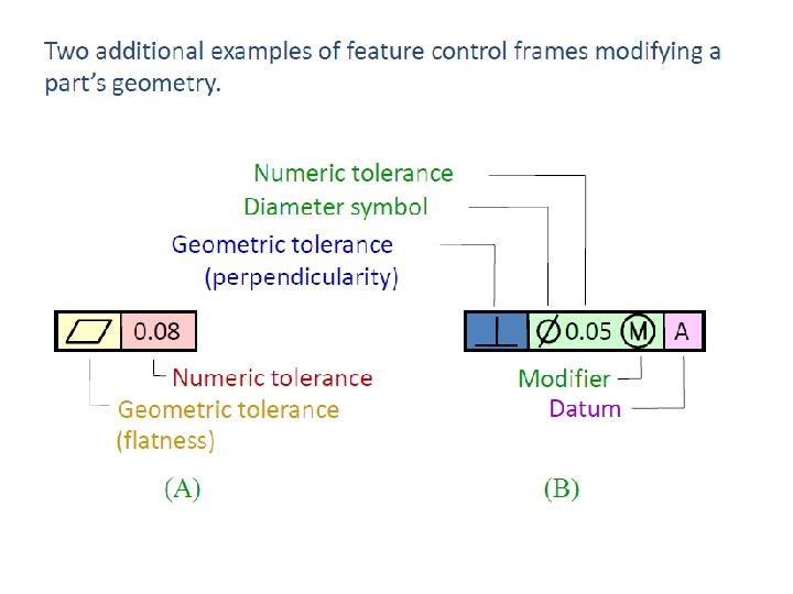
Feature control frame
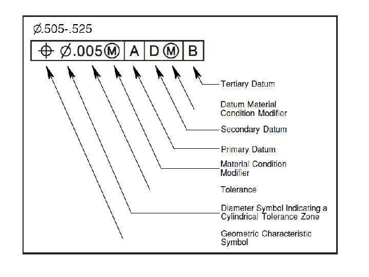

How to read ? The position tolerance requires that The axis of the controlled feature Must lie within a cylindrical tolerance zone. 005 in diameter At regardless of feature size (RFS) Oriented and located with basic dimensions to datum feature A at regardless of material boundary (RMB)

How to read? The position tolerance requires that The axis of the controlled feature Must lie within a cylindrical tolerance zone. 005 in diameter At maximum material condition (MMC) Oriented and located with basic dimensions to datum feature A at maximum material boundary (MMB)

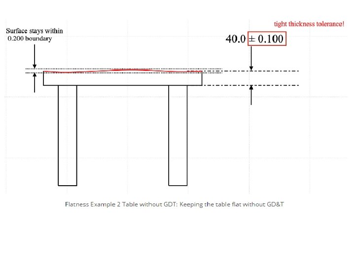
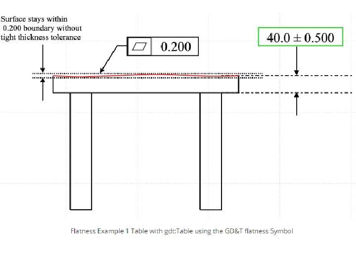
Flatness A two dimensional tolerance zone defined by two parallel planes within which the entire surface must lie.

Example • If you want to make sure that a tabletop is perfectly flat, if you did not have a flatness callout, you would have to constrain the height of the table very tightly to make sure that the entire surface is straight. • With flatness, you can allow the table to be flat without constraining the tabletop thickness very tight. • (You would be rejecting tables that were good thicknesses and normally in spec if using GD&T)

Straightness A condition where an element of a surface or an axis is a straight line.

A steel bar is welded in a T pattern to another steel bar. If you want to make sure that the surface of the tube is always uniform, where the weld occurs, you would need to either greatly tighten the dimensional diameter of the tube, (which would be very costly for such a simple part!), or callout straightness along the mating surface.

Without GD&T With GD&T

Straightness vs flatness • Straightness can be considered the 2 Dimensional version of Flatness as both are measured without a datum and controls and refine the size of the feature. • While flatness measures the variance across a 2 D plane, Straightness only measures the variance on a straight line.
 • The circularity symbol is used to describe how close an object")
Circularity (Roundness) • The circularity symbol is used to describe how close an object should be to a true circle. • Sometimes called roundness, circularity is a 2 -Dimensional tolerance that controls the overall form of a circle ensuring it is not too oblong, square, or out of round. • Roundness is independent of any datum feature and only is always less than the diameter dimensional tolerance of the part. • Circularity essentially make a cross section of a cylindrical or round feature and determines if the circle formed in that cross section is round.

If you had a hole that was around a rotating shaft, Both pieces should be circular and have a tight tolerance. Without circularity, the diameter of the hole and shaft would have to be very tight and more expensive to make.

Cylindricity • Cylindricity is actually a combination of circularity and straightness. • A condition on a surface of revolution in which all points of the surface are equidistant from a common axis. • The cylindricity symbol is used to describe how close an object conforms to a true cylinder. • Cylindricity is a 3 -Dimensional tolerance that controls the overall form of a cylindrical feature to ensure that it is round enough and straight enough along its axis.

If you had a bushing that was to be pressed into a housing, the bushing would take the form of the housing bore when inserted. To ensure that the bushing maintains its round shape, and wears evenly along its surface, the housing bore needs to be very cylindrical. To do this without GD&T you would need very tight dimensions on the diameter of the bore, which may be very hard to control when being machined (and expensive)

Circularity vs cylindricity • Circularity is the 2 D version of cylindricity. While cylindricity ensures all the points on a cylinder fall into a tolerance, circularity only is concerned with individual measurements around the surface in one circle. • If you think of a stack of coins, circularity would be a measurement around one coin while cylindricity would have to measure the entire stack.

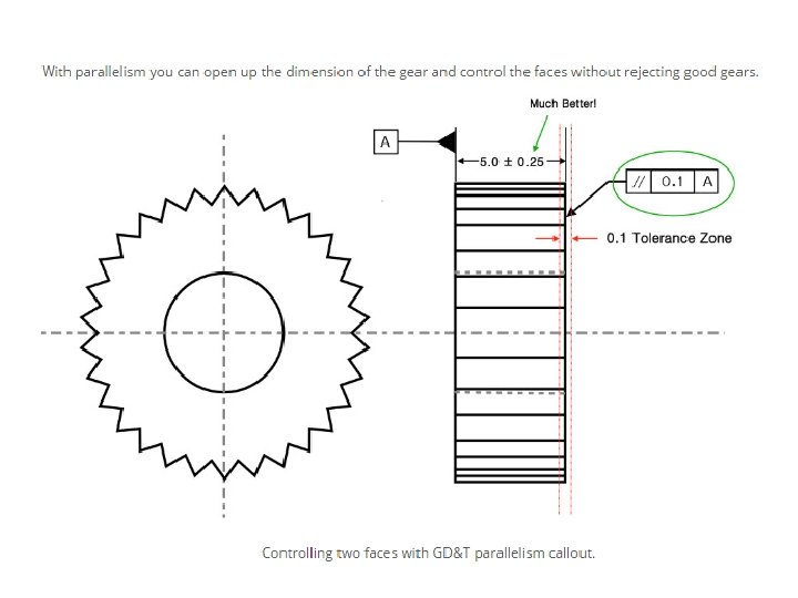
Parallelism • Parallelism is a fairly common symbol that describes a parallel orientation of one referenced feature to a datum surface or line. • Parallelism is quite simple to measure. Like flatness, a gauge is run across the reference surface or feature. However unlike flatness, the part is constrained against a granite block or flat plane that acts as the datum surface where it is measured.

A gear has to maintain constant axial load on both faces. To ensure even contact one side of the gear is held parallel to the other side. To do this without parallelism, the gear width would have to be tightly controlled, which could be very difficult to do.

Perpendicularity The condition of a surface, axis, median plane, or line which is exactly at 90 degrees with respect to a datum plane or axis. • Perpendicularity is a fairly common symbol that requires the referenced surface or line to be perpendicular or 90° from a datum surface or line. Perpendicularity can reference a 2 D line, but more commonly it describes the orientation of one surface plane perpendicular to another datum plane. • The normal form or Surface Perpendicularity is a tolerance that controls Perpendicularity between two 90° surfaces, or features. Surface Perpendicularity is controlled with two parallel planes acting as its tolerance zone. • Axis Perpendicularity is a tolerance that controls how perpendicular a specific axis needs to be to a datum. Axis Perpendicularity is controlled by a cylinder around a theoretical perfectly parallel axis. •


The edge of a stopping block for a rail must form a 90° to ensure proper mating contact takes place. The base of the block is will be our datum and the face where the stopping block makes contact is our referenced surface. To ensure that this face is always perpendicular and flat to make good contact, you would need to both tightly control the angle and the dimensional width of the part.

With perpendicularity you can open up the width dimension and control the face’s angle containing the part very tightly. Your tolerance zone remains the same, but your part is now easer to control and fabricate.

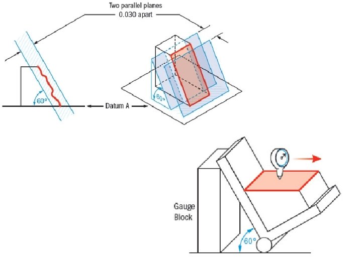
Angularity • The distance between two parallel planes, inclined at a specified basic angle in which the surface, axis, or center plane of the feature must lie. • Angularity is the symbol that describes the specific orientation of one feature to another at a referenced angle. • Two parallel planes or lines which are oriented at the specified angle in relation to a datum. All points on the referenced surface must fall into this tolerance zone. • Angularity does not directly control the angle of the referenced surface; it controls the envelope (like flatness) that the entire surface can lie. • Remember – You are not controlling the angle with angularity – you are controlling the surface to fall within the specified dimensional tolerance in millimeters!

Position • True position is defined as the total permissible variation that a feature can have from its “true” position. • A zone within which the center, axis, or center plane of a feature of size is permitted to vary from its true (theoretically exact) position.
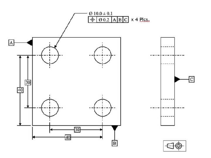

The holes center is calculated, usually by a CMM and compared to the true location. As long as the holes center is in the blue tolerance zone of 0. 2 mm specified by the feature control frame, the part is in tolerance.
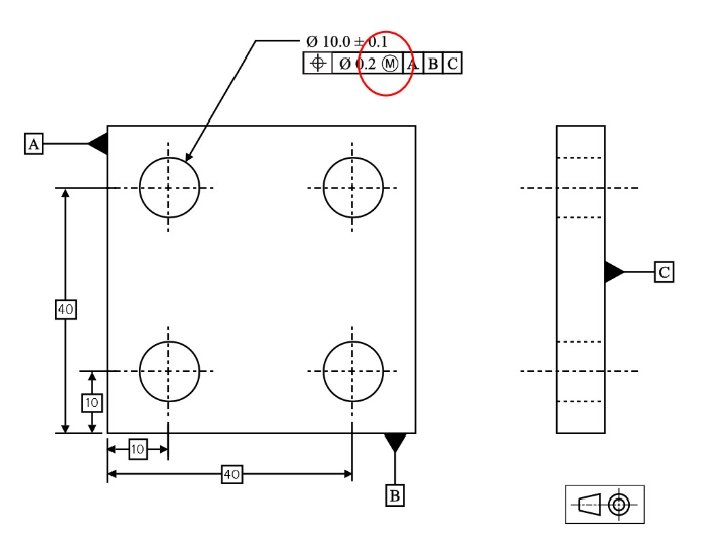

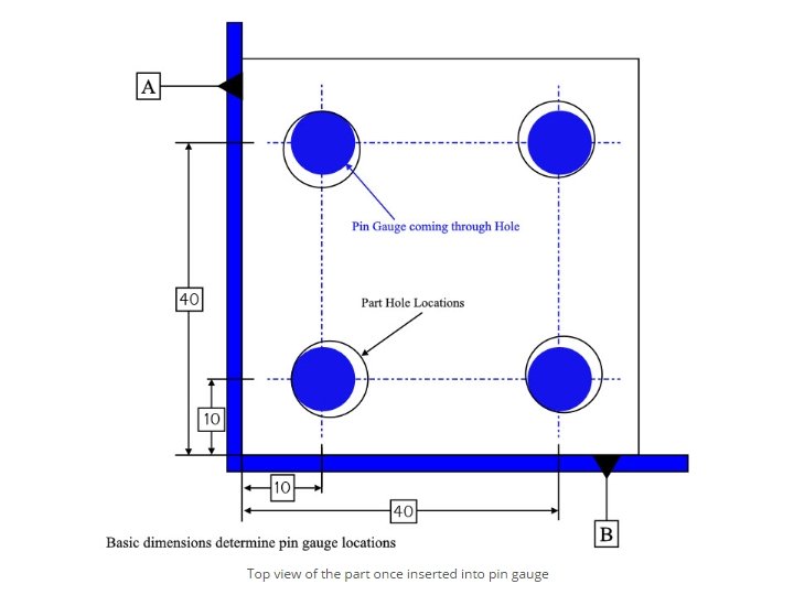
Formula for a the functional gauge to measure the true position of all holes: Individual Pin Diameters = Min hole Ø -True position tolerance This example Pin Ø = 9. 9 – 0. 2 = Ø 9. 7 Location of pins: Same specifications

Concentricity, sometimes called coaxially, is a tolerance that controls the central axis of the referenced feature, to a datum axis. Concentricity is considered one of the most difficult GD&T symbols to measure for due to its difficulty in establishing the mid points of the feature. First you must establish a datum axis which to measure, Once the datum axis is established you must now take measure many a series of cross sections

• Concentricity is considered one of the most difficult GD&T symbols to measure for due to its difficulty in establishing the mid points of the feature. First you must establish a datum axis which to measure, Once the datum axis is established you must now take measure many a series of cross sections

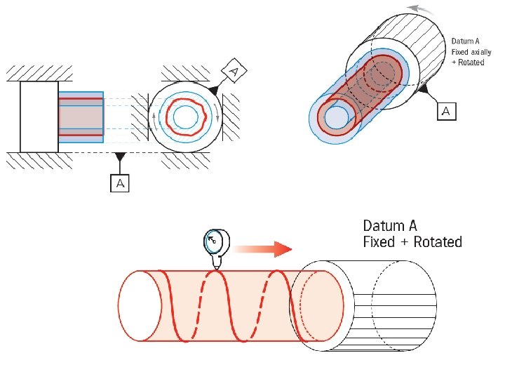
An intermediate shaft in a transmission is composed of two different diameter sections which are coaxial. Datum A is the drive side and relatively fixed with bearings to the housing, The referenced surface B is desired to be concentric with Datum A to avoid oscillations at high speed.


Symmetry GD&T Symmetry is a 3 -Dimensional tolerance that is used to ensure that two features on a part are uniform across a datum plane. An established “true” central plane is established from the datum and for the symmetry to be in tolerance, the median distance between the every point on the two surface features need to fall near that central plane.


Profile of a surface • A uniform three dimensional zone contained between two envelope surfaces separated by the tolerance zone across the entire length of a surface. • Profile of a surface describes a 3 -Dimensional tolerance zone around a surface, usually which is an advanced curve or shape. • If it is called out on a curved surface, like a fillet on a welded part, the entire surface where the radius is has to fall within the tolerance zone. • Profile controls all the points along the surface within a tolerance range that directly mimics the designed profile.

Profile is usually measured using a CMM due to the complexity of some of the surfaces that are called out. The CMM would compare the 3 D scan of the profile to the dimensions called out on the drawing to see if it was in spec.

If you have a curved surface and want to ensure that every point falls within a specific tolerance range, you would call out profile of a surface. This could be considered an advanced curve that could only be controlled with use of a profile tolerance.

Profile of a line • A uniform two dimensional zone limited by two parallel zone lines extending along the length of a feature. • Profile of a line describes a tolerance zone around any line in any feature, usually of a curved shape. Profile of a line is a 2 -Dimensional tolerance range that can be applied to any linear tolerance.

Sometimes profile of a line is used in conjunction with profile of a surface. In these cases the line profile tolerance will be tighter than the surface tolerance. This ensures that along any specific cross section of the profile, the profile remains true, while also ensuring that each cross section of the part would be within a wider tolerance range when compared together.

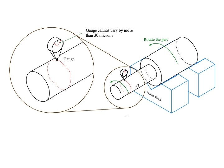
Runout total • A composite tolerance used to control the relationship of one or more features of a part to a datum axis during a full 360 degree rotation about the datum axis. • Total Runout is how much one entire feature or surface varies with respect to a datum when the part is rotated 360° around the datum axis. • Total runout controls both the amount of variation in the surface as the part is rotated, but the amount of variation in the axial dimension. • Both radial variation and axial variation are measured and held within the tolerance. Total Runout is usually called on a part that is rotated about an axis where the entire surface is critical to be in spec.

• An axle is normally under high stress and needs to fit evenly in a bushing (not shown). If the referenced surface does not make even, stable contact with the housing bushings the axle will wear unevenly leading to eventual failure. • Surface ‘A’(datum) is controlled with a roller bearing and should be axially aligned with the reference surface. Total Runout is called in the same way as Runout

Runout circular 2 -Dimensional circular tolerance zone that is defined by a datum axis where all points on the called surface must fall into. The zone is a direct reference to the datum feature. Runout is the total variation that the reference surface can have, when the part is rotated around the datum’s true axis.

If no material condition symbol is specified for the tolerance or datum reference of a size feature in a feature control frame, RFS (Regardless of Feature Size) automatically applies.

Important terms

Important terms 1. Size: - It is a number expressed in a particular unit in the measurement of length. 2. Basic Size: - It is the size based on which the dimensional deviations are given. 3. Actual Size: - It is the size of the component by actual measurement after it is manufactured. It should lie between the two limits of size.

Important terms 4. Limits of size: - These are the extreme permissible sizes within which the operator is expected to make the component. Maximum limit of size is the greater of the two limit size, whereas the Minimum limit of size is the smaller of the two limit of size. 5. Hole: - In the B. I. S. system of limits and fits, all internal features of a component including those which are not cylindrical are designated as ‘Hole’. 6. Shaft: - In the B. I. S. system of limits and fits, all external features of a component including those which are not cylindrical are designated as ‘Shaft’.

Important terms 7. Interchangeability: - When components are mass produced, unless they are interchangeable, the purpose of mass production is not fulfilled. By interchangeability, we mean that identical components, manufactured by different personnel under different environments, can be assembled and replaced without any further rectification during the assembly stage, without affecting the functioning of the component when assembled.

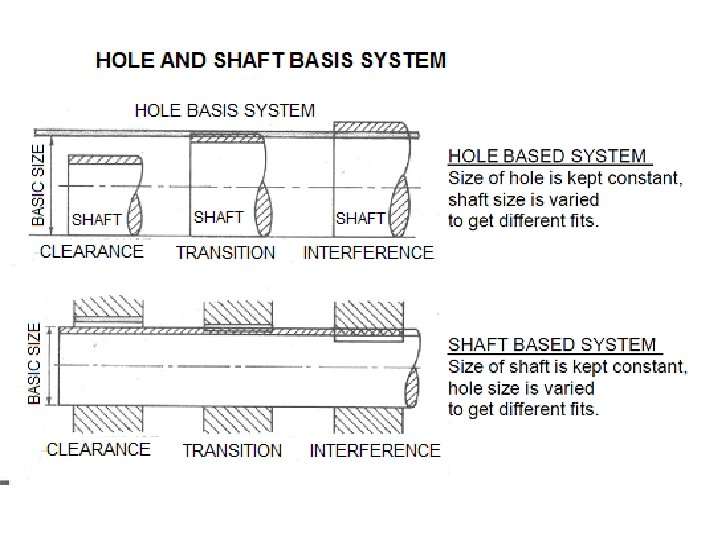
Important terms 8. Hole Basis System: - Where the size of the hole is kept constant and the size of the shaft is varied to get the different class of fits, then it is known as the hole basis system. 9. Shaft Basis System: - Where the size of the shaft is kept constant and the variations given to the hole to get the different class of fits, then it is known as the shaft basis system.

Rules • Rule #1 states that where only a tolerance of size is specified, the limits of size of an individual feature prescribe the extent to which variations in its geometric form, as well as size, are allowed.

Rules • Rule #2 states that, in a feature control frame, RFS (regardless of feature size) automatically applies to individual tolerances of size and to datum features of size. MMC and LMC must be specified when these conditions are required.
 is the default condition")
Regardless of Feature Size • Regardless of Feature Size (RFS) is the default condition of all geometric tolerances by rule #2 of GD&T and requires no callout. Regardless of feature size simply means that whatever GD&T callout you make, is controlled independently of the size dimension of the part. • For simplicity, the definitions of all the GD&T symbols are by default, stated as Regardless of Feature Size.

In the following example, no material modifiers are called out, RFS would be implied and the control for the parts would be like this:

END
 8 simple questions, 20 marks")
QUIZ 1 • • Week 4 (10 Mac 2016) 8 simple questions, 20 marks Covers 5% of total carry marks Introduction, chapter 1, chapter 2
- Slides: 89