
Gauge Design Configurations for High Charge Discharge Rate



- Slides: 32
Gauge Design Configurations for High Charge / Discharge Rate Applications Thomas Cosby TI Information – Selective Disclosure. Battery Management Deep Dive 2015 FULLY CHARGED! Jump-start your Battery System Design – www. TI. com/battery Expert Solutions Easy-to-use Robust Design Tools Innovative Products 1
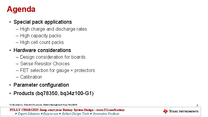
Agenda • Special pack applications – High charge and discharge rates – High capacity packs – High cell count packs • Hardware considerations – – Design consideration for boards Sense Resistor Choices FET selection for gauge + protectors Calibration • Parameter configuration • Products (bq 78350, bq 34 z 100 -G 1) TI Information – Selective Disclosure. Battery Management Deep Dive 2015 FULLY CHARGED! Jump-start your Battery System Design – www. TI. com/battery Expert Solutions Easy-to-use Robust Design Tools Innovative Products 2
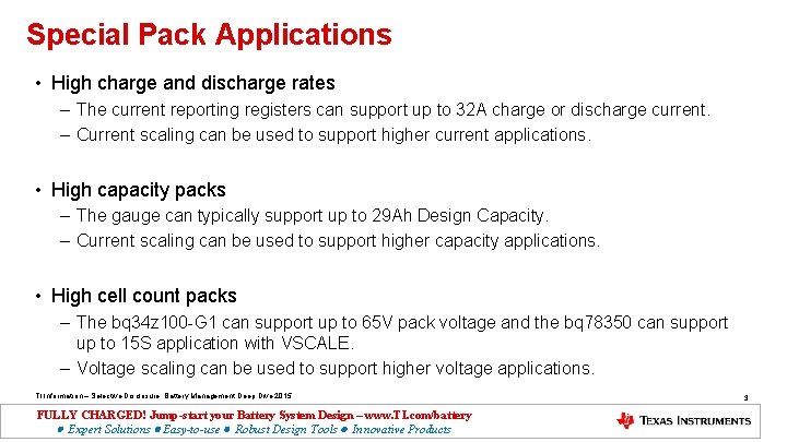
Special Pack Applications • High charge and discharge rates – The current reporting registers can support up to 32 A charge or discharge current. – Current scaling can be used to support higher current applications. • High capacity packs – The gauge can typically support up to 29 Ah Design Capacity. – Current scaling can be used to support higher capacity applications. • High cell count packs – The bq 34 z 100 -G 1 can support up to 65 V pack voltage and the bq 78350 can support up to 15 S application with VSCALE. – Voltage scaling can be used to support higher voltage applications. TI Information – Selective Disclosure. Battery Management Deep Dive 2015 FULLY CHARGED! Jump-start your Battery System Design – www. TI. com/battery Expert Solutions Easy-to-use Robust Design Tools Innovative Products 3
High Charge and Discharge Rates (> 32 A) • If we need to support a 48 A discharge current, then that pack will be scale by 48 A/32 A = 1. 5 Scale factor rounded up to 2 x. • We can fool the gauge by current calibration: for a 5 mohm Rsense, if we calibrate at an actual current of 4 A, we can use the value 2 A for calibration so the CC Gain and CC Delta would become 10 mohm. We now have a calibration ratio of 50% • Modify all current and capacity related data flash values by the scale factor, example: 1 st level OC from 6000 m. A to 3000 m. A; pay attention to sleep current/quit current, as these are impacted as well; also modify Design. Capacity, Design. Energy • Exception is AFE OC Dsg, AFE SC Chg and Dsg: calculate these values based on the voltage = true Rsense * true current • All reported current and capacity parameters will need to be scaled up by the scale factor to restore the true values. TI Information – Selective Disclosure. Battery Management Deep Dive 2015 FULLY CHARGED! Jump-start your Battery System Design – www. TI. com/battery Expert Solutions Easy-to-use Robust Design Tools Innovative Products 4
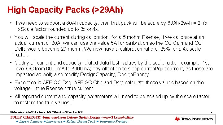
High Capacity Packs (>29 Ah) • If we need to support a 80 Ah capacity, then that pack will be scale by 80 Ah/29 Ah = 2. 75 Scale factor rounded up to 3 x or 4 x. • You will scale the current during calibration: for a 5 mohm Rsense, if we calibrate at an actual current of 20 A, we can use the value 5 A for calibration so the CC Gain and CC Delta would become 20 mohm. We now have a calibration ratio of 25% for a 4 x scale factor. • Modify all current and capacity related data flash values by the scale factor, example: 1 st level OC from 6000 m. A to 3000 m. A; pay attention to sleep current/quit current, as these are impacted as well; also modify Design. Capacity, Design. Energy • Exception is AFE OC Dsg, AFE SC Chg and Dsg: calculate these values based on the voltage = true Rsense * true current • All reported current and capacity parameters will need to be scaled up by the scale factor to restore the true values. TI Information – Selective Disclosure. Battery Management Deep Dive 2015 FULLY CHARGED! Jump-start your Battery System Design – www. TI. com/battery Expert Solutions Easy-to-use Robust Design Tools Innovative Products 5
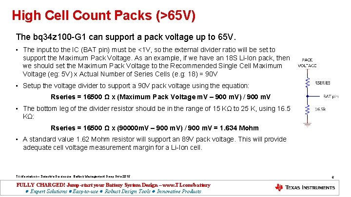
High Cell Count Packs (>65 V) The bq 34 z 100 -G 1 can support a pack voltage up to 65 V. • The input to the IC (BAT pin) must be <1 V, so the external divider ratio will be set to support the Maximum Pack Voltage. As an example, if we have an 18 S Li-Ion pack, then we should set the Maximum Pack Voltage to the Recommended Single Cell Maximum Voltage (eg: 5 V) x Actual Number of Series Cells (e. g: 18) = 90 V • Setup the voltage divider to support a 90 V pack voltage using the equation: Rseries = 16500 Ω x (Maximum Pack Voltage m. V – 900 m. V) / 900 m. V • The bottom leg of the divider resistor should be in the range of 15 KΩ to 25 K, using 16. 5 KΩ: Rseries = 16500 Ω x (90000 m. V – 900 m. V) / 900 m. V = 1. 634 Mohm • A standard value 1. 62 Mohm resistor will support an 89 V pack voltage. This will provide adequate cell voltage measurement margin for a Li-Ion cell. TI Information – Selective Disclosure. Battery Management Deep Dive 2015 FULLY CHARGED! Jump-start your Battery System Design – www. TI. com/battery Expert Solutions Easy-to-use Robust Design Tools Innovative Products 6
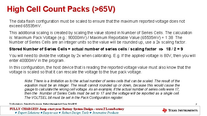
High Cell Count Packs (>65 V) The data flash configuration must be scaled to ensure that the maximum reported voltage does not exceed 65535 m. V. This additional scaling is created by scaling the value stored in Number of Series Cells. The calculation is: Maximum Pack Voltage (e. g. : 90000 m. V) / Maximum Reportable Value (65535 m. V) = 1. 38 The Number of Series Cells are an integer units so the value will be rounded up, use a 2 x scaling factor. Stored Number of Series Cells = actual number of series cells / scaling factor 18 / 2 = 9 You will need to divide the voltage by 2 x when calibrating. E. g. If the applied voltage is 80 V, then you will enter 40000 m. V in the program. In this configuration, the host device that is reading the reported voltage value must also know that the voltage is scaled so that it can rescale the voltage to the true pack voltage. Note: There is a limitation as to the actual number of series cells that can be scaled. The result of the equation must be an integer. The result cannot rounded up or down, because this would cause the gauge to calculate the wrong cell voltage. As an example, if the actual number of series cells were 17, then the Number of Series Cells must be set to 17 and the voltage will be reported as a single cell. The VOLTSEL bit must be set in the Pack Configuration register. TI Information – Selective Disclosure. Battery Management Deep Dive 2015 FULLY CHARGED! Jump-start your Battery System Design – www. TI. com/battery Expert Solutions Easy-to-use Robust Design Tools Innovative Products 7
Hardware considerations • Design consideration for boards – Layout for high current paths. – ESD • Sense resistor choices and layout • FET selection for gauge + protectors • Calibration TI Information – Selective Disclosure. Battery Management Deep Dive 2015 FULLY CHARGED! Jump-start your Battery System Design – www. TI. com/battery Expert Solutions Easy-to-use Robust Design Tools Innovative Products 8
Design Consideration for Boards • The coulomb counting network is probably the most important section to consider in the layout. • The high current paths are the next most important. • The gauge should be not placed inside the current loop for the best gauging accuracy. Transients and fields can induce error into current and voltage measurements. • Use high frequency bypass capacitors and spark gaps to shunt ESD transients. TI Information – Selective Disclosure. Battery Management Deep Dive 2015 FULLY CHARGED! Jump-start your Battery System Design – www. TI. com/battery Expert Solutions Easy-to-use Robust Design Tools Innovative Products 9
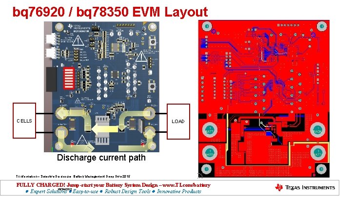
bq 76920 / bq 78350 EVM Layout CELLS LOAD Discharge current path TI Information – Selective Disclosure. Battery Management Deep Dive 2015 FULLY CHARGED! Jump-start your Battery System Design – www. TI. com/battery 10/24/2012 Expert Solutions Easy-to-use Robust Design Tools Innovative Products 10
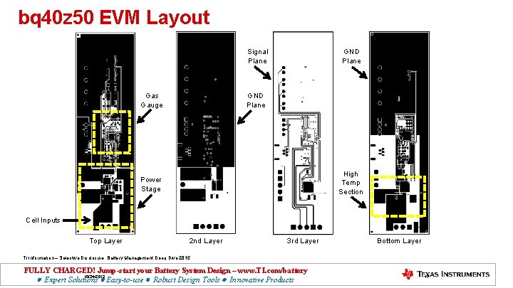
bq 40 z 50 EVM Layout Signal Plane GND Plane Gas Gauge High Temp Section Power Stage Cell Inputs Top Layer 2 nd Layer 3 rd Layer Bottom Layer TI Information – Selective Disclosure. Battery Management Deep Dive 2015 FULLY CHARGED! Jump-start your Battery System Design – www. TI. com/battery 10/24/2012 Expert Solutions Easy-to-use Robust Design Tools Innovative Products 11
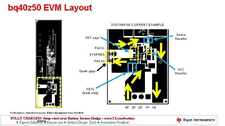
bq 40 z 50 EVM Layout DISCHARGE CURRENT EXAMPLE Sense Resistor FET caps PACKSYSPRES PACK+ VCC Resistor Spark gaps FETs (back side) 4 P 3 P 2 P 1 P 1 N TI Information – Selective Disclosure. Battery Management Deep Dive 2015 FULLY CHARGED! Jump-start your Battery System Design – www. TI. com/battery 10/24/2012 Expert Solutions Easy-to-use Robust Design Tools Innovative Products 12
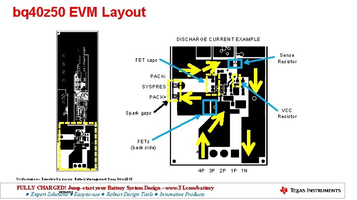
bq 40 z 50 EVM Layout DISCHARGE CURRENT EXAMPLE Sense Resistor FET caps PACKSYSPRES PACK+ VCC Resistor Spark gaps FETs (back side) 4 P 3 P 2 P 1 P 1 N TI Information – Selective Disclosure. Battery Management Deep Dive 2015 FULLY CHARGED! Jump-start your Battery System Design – www. TI. com/battery 10/24/2012 Expert Solutions Easy-to-use Robust Design Tools Innovative Products 13
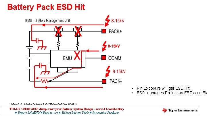
Battery Pack ESD Hit • Pin Exposure will get ESD Hit • ESD damages Protection FETs and BM TI Information – Selective Disclosure. Battery Management Deep Dive 2015 FULLY CHARGED! Jump-start your Battery System Design – www. TI. com/battery 10/24/2012 Expert Solutions Easy-to-use Robust Design Tools Innovative Products 14
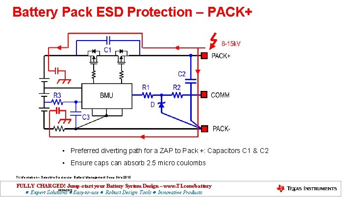
Battery Pack ESD Protection – PACK+ • Preferred diverting path for a ZAP to Pack +: Capacitors C 1 & C 2 • Ensure caps can absorb 2. 5 micro coulombs TI Information – Selective Disclosure. Battery Management Deep Dive 2015 FULLY CHARGED! Jump-start your Battery System Design – www. TI. com/battery 10/24/2012 Expert Solutions Easy-to-use Robust Design Tools Innovative Products 15
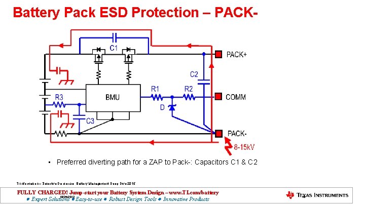
Battery Pack ESD Protection – PACK- • Preferred diverting path for a ZAP to Pack-: Capacitors C 1 & C 2 TI Information – Selective Disclosure. Battery Management Deep Dive 2015 FULLY CHARGED! Jump-start your Battery System Design – www. TI. com/battery 10/24/2012 Expert Solutions Easy-to-use Robust Design Tools Innovative Products 16
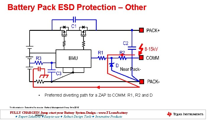
Battery Pack ESD Protection – Other • Preferred diverting path for a ZAP to COMM: R 1, R 2 and D TI Information – Selective Disclosure. Battery Management Deep Dive 2015 FULLY CHARGED! Jump-start your Battery System Design – www. TI. com/battery 10/24/2012 Expert Solutions Easy-to-use Robust Design Tools Innovative Products 17
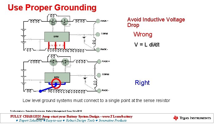
Use Proper Grounding Avoid Inductive Voltage Drop Wrong V = L di/dt Right Low level ground systems must connect to a single point at the sense resistor TI Information – Selective Disclosure. Battery Management Deep Dive 2015 FULLY CHARGED! Jump-start your Battery System Design – www. TI. com/battery 10/24/2012 Expert Solutions Easy-to-use Robust Design Tools Innovative Products 18
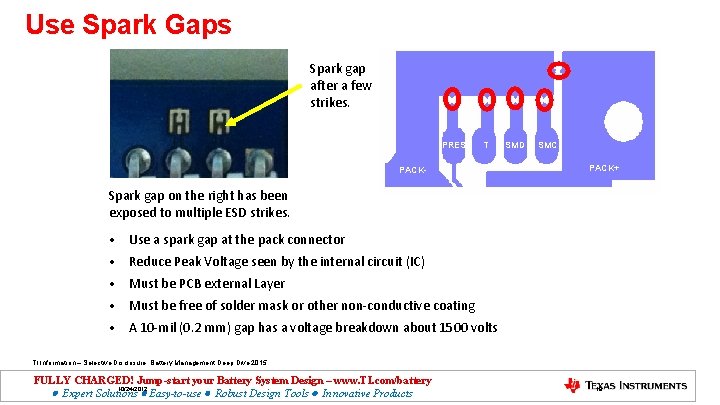
Use Spark Gaps Spark gap after a few strikes. PRES T PACK- SMD SMC PACK+ Spark gap on the right has been exposed to multiple ESD strikes. • Use a spark gap at the pack connector • Reduce Peak Voltage seen by the internal circuit (IC) • Must be PCB external Layer • Must be free of solder mask or other non-conductive coating • A 10 -mil (0. 2 mm) gap has a voltage breakdown about 1500 volts TI Information – Selective Disclosure. Battery Management Deep Dive 2015 FULLY CHARGED! Jump-start your Battery System Design – www. TI. com/battery 10/24/2012 Expert Solutions Easy-to-use Robust Design Tools Innovative Products 19
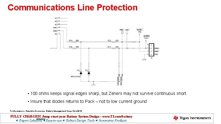
Communications Line Protection • 100 ohms keeps signal edges sharp, but Zeners may not survive continuous short • Insure that diodes returns to Pack – not to low current ground TI Information – Selective Disclosure. Battery Management Deep Dive 2015 FULLY CHARGED! Jump-start your Battery System Design – www. TI. com/battery 10/24/2012 Expert Solutions Easy-to-use Robust Design Tools Innovative Products 20
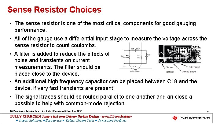
Sense Resistor Choices • The sense resistor is one of the most critical components for good gauging performance. • All of the gauge use a differential input stage to measure the voltage across the sense resistor to count coulombs. • A filter is added to reduce the effects of noise and transients on current measurements. The filter should be placed close to the device. • An additional high frequency capacitor can be placed between C 18 and the device, if very fast transients are present. • The signal traces should be routed parallel to one another and an close a possible to help with common-mode rejection. TI Information – Selective Disclosure. Battery Management Deep Dive 2015 FULLY CHARGED! Jump-start your Battery System Design – www. TI. com/battery Expert Solutions Easy-to-use Robust Design Tools Innovative Products 21
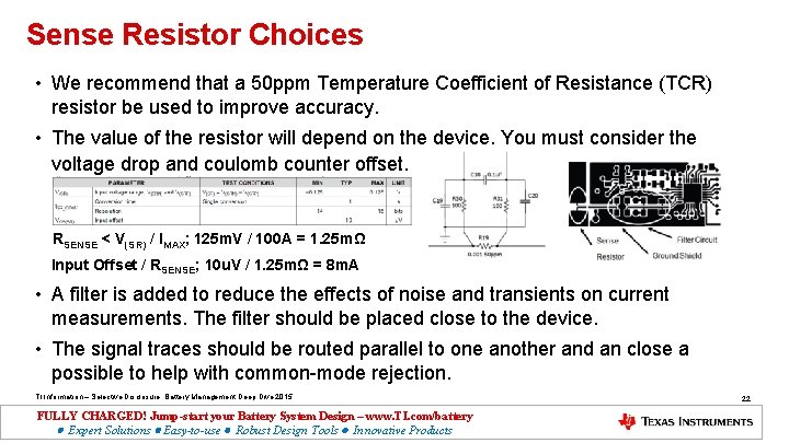
Sense Resistor Choices • We recommend that a 50 ppm Temperature Coefficient of Resistance (TCR) resistor be used to improve accuracy. • The value of the resistor will depend on the device. You must consider the voltage drop and coulomb counter offset. RSENSE < V(SR) / IMAX; 125 m. V / 100 A = 1. 25 mΩ Input Offset / RSENSE; 10 u. V / 1. 25 mΩ = 8 m. A • A filter is added to reduce the effects of noise and transients on current measurements. The filter should be placed close to the device. • The signal traces should be routed parallel to one another and an close a possible to help with common-mode rejection. TI Information – Selective Disclosure. Battery Management Deep Dive 2015 FULLY CHARGED! Jump-start your Battery System Design – www. TI. com/battery Expert Solutions Easy-to-use Robust Design Tools Innovative Products 22
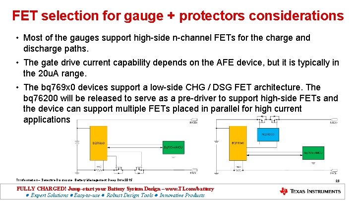
FET selection for gauge + protectors considerations • Most of the gauges support high-side n-channel FETs for the charge and discharge paths. • The gate drive current capability depends on the AFE device, but it is typically in the 20 u. A range. • The bq 769 x 0 devices support a low-side CHG / DSG FET architecture. The bq 76200 will be released to serve as a pre-driver to support high-side FETs and the device can support multiple FETs placed in parallel for high current applications. TI Information – Selective Disclosure. Battery Management Deep Dive 2015 FULLY CHARGED! Jump-start your Battery System Design – www. TI. com/battery Expert Solutions Easy-to-use Robust Design Tools Innovative Products 23
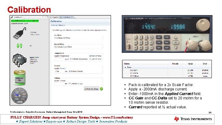
Calibration • • Pack is calibrated for a 2 x Scale Factor. Apply a -2000 m. A discharge current. Enter -1000 m. A in the Applied Current field. CC Gain and CC Delta set to 20 mohm for a 10 mohm sense resistor. • Current reported at ½ actual value. TI Information – Selective Disclosure. Battery Management Deep Dive 2015 FULLY CHARGED! Jump-start your Battery System Design – www. TI. com/battery Expert Solutions Easy-to-use Robust Design Tools Innovative Products 24
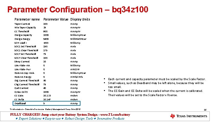
Parameter Configuration – bq 34 z 100 Parameter name Parameter Value Display Units Taper Current Min Taper Capacity CC Threshold Design Capacity Design Energy SOH Load I SOC 1 Set Threshold SOC 1 Clear Threshold SOCF Set Threshold SOCF Clear Threshold Sleep Current User Rate-m. A User Rate-Pwr Reserve Cap-m. Ah Reserve Energy Dsg Current Threshold Chg Current Threshold Quit Current Qmax Cell 0 CC Gain CC Delta Deadband 100 25 900 1000 5400 -400 150 175 75 100 10 0 0 60 75 40 1000 10. 123 10. 147 5 m. Amp. Hr Milli. Amp. Hour Milli. Watt. Hour Milli. Amp m. Ah m. Amp Milli. Amp m. W/c. W Milli. Amp. Hour m. Wh/c. Wh m. Amp. Hr mohm m. Amp • Each current and capacity parameter must be scaled by the Scale Factor. • Small values, such as Deadband may be left alone, because they will be too small. • The CC Gain and CC Delta will be scaled when the current is calibrated. Their values will be set to the Scale Factor x Rsense. TI Information – Selective Disclosure. Battery Management Deep Dive 2015 FULLY CHARGED! Jump-start your Battery System Design – www. TI. com/battery Expert Solutions Easy-to-use Robust Design Tools Innovative Products 25
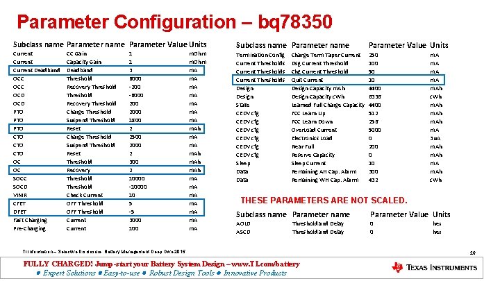
Parameter Configuration – bq 78350 Subclass name Parameter Value Units Current Deadband OCC OCD PTO PTO CTO CTO OC OC SOCD VIMR CFET DFET Fast Charging Pre-Charging CC Gain Capacity Gain Deadband Threshold Recovery Threshold Charge Threshold Suspend Threshold Reset Threshold Recovery Threshold Check Current OFF Threshold Current 1 1 3 6000 -200 -6000 2000 1800 2 2500 2000 2 300 2 10000 -10000 10 5 -5 3000 100 m. Ohm m. A m. Ah m. A m. A Subclass name Parameter Value Units Termination Config Current Thresholds Design State CEDV cfg CEDV cfg Sleep Data 250 100 50 10 4400 6336 4400 512 256 5000 0 200 0 10 300 432 Charge Term Taper Current Dsg Current Threshold Chg Current Threshold Quit Current Design Capacity m. Ah Design Capacity c. Wh Learned Full Charge Capacity FCC Learn Up FCC Learn Down Over. Load Current Electronics Load Near Full Reserve Capacity Sleep Current Remaining AH Cap. Alarm Remaining WH Cap. Alarm m. A m. Ah c. Wh m. Ah m. A 3 u. A m. Ah c. Wh THESE PARAMETERS ARE NOT SCALED. Subclass name Parameter Value Units AOLD ASCD 0 0 Threshold and Delay TI Information – Selective Disclosure. Battery Management Deep Dive 2015 FULLY CHARGED! Jump-start your Battery System Design – www. TI. com/battery Expert Solutions Easy-to-use Robust Design Tools Innovative Products hex 26
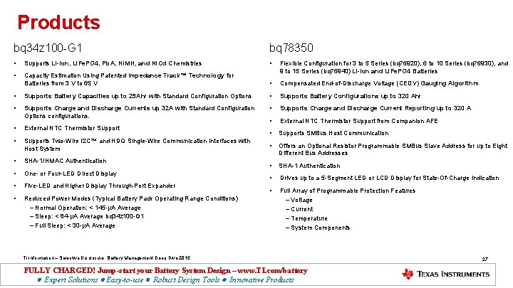
Products bq 34 z 100 -G 1 bq 78350 • Supports Li-Ion, Li. Fe. PO 4, Pb. A, Ni. MH, and Ni. Cd Chemistries • • Capacity Estimation Using Patented Impedance Track™ Technology for Batteries from 3 V to 65 V Flexible Configuration for 3 to 5 Series (bq 76920), 6 to 10 Series (bq 76930), and 9 to 15 Series (bq 76940) Li-Ion and Li. Fe. PO 4 Batteries • Compensated End-of-Discharge Voltage (CEDV) Gauging Algorithm • Supports Battery Capacities up to 29 Ahr with Standard Configuration Options • Supports Battery Configurations up to 320 Ahr • Supports Charge and Discharge Currents up 32 A with Standard Configuration Options configurations. • Supports Charge and Discharge Current Reporting up to 320 A • External NTC Thermistor Support from Companion AFE • External NTC Thermistor Support • Supports SMBus Host Communication • Supports Two-Wire I 2 C™ and HDQ Single-Wire Communication Interfaces with Host System • Offers an Optional Resistor Programmable SMBus Slave Address for up to Eight Different Bus Addresses • SHA-1/HMAC Authentication • SHA-1 Authentication • One- or Four-LED Direct Display • Drives up to a 5 -Segment LED or LCD Display for State-Of-Charge Indication • Five-LED and Higher Display Through Port Expander • • Reduced Power Modes (Typical Battery Pack Operating Range Conditions) – Normal Operation: < 145 -μA Average – Sleep: < 84 -μA Average bq 34 z 100 -G 1 – Full Sleep: < 30 -μA Average Full Array of Programmable Protection Features – Voltage – Current – Temperature – System Components TI Information – Selective Disclosure. Battery Management Deep Dive 2015 FULLY CHARGED! Jump-start your Battery System Design – www. TI. com/battery Expert Solutions Easy-to-use Robust Design Tools Innovative Products 27
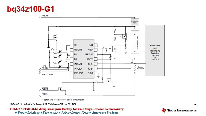
bq 34 z 100 -G 1 TI Information – Selective Disclosure. Battery Management Deep Dive 2015 FULLY CHARGED! Jump-start your Battery System Design – www. TI. com/battery Expert Solutions Easy-to-use Robust Design Tools Innovative Products 28
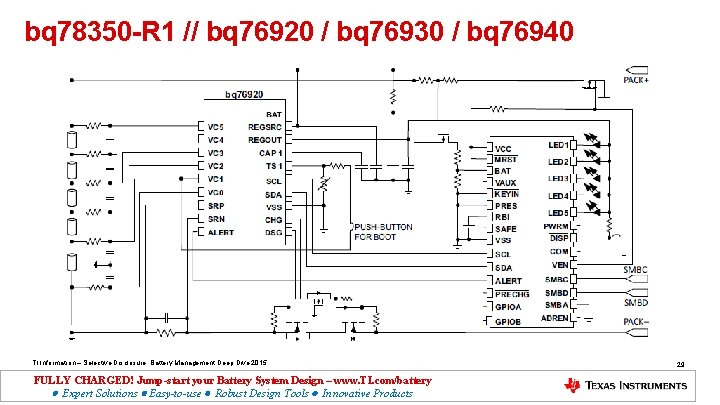
bq 78350 -R 1 // bq 76920 / bq 76930 / bq 76940 TI Information – Selective Disclosure. Battery Management Deep Dive 2015 FULLY CHARGED! Jump-start your Battery System Design – www. TI. com/battery Expert Solutions Easy-to-use Robust Design Tools Innovative Products 29
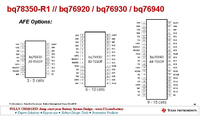
bq 78350 -R 1 // bq 76920 / bq 76930 / bq 76940 AFE Options: 3 - 5 cells 6 - 10 cells TI Information – Selective Disclosure. Battery Management Deep Dive 2015 FULLY CHARGED! Jump-start your Battery System Design – www. TI. com/battery Expert Solutions Easy-to-use Robust Design Tools Innovative Products 9 - 15 cells 30
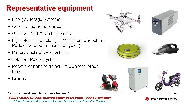
Representative equipment • Energy Storage Systems • Cordless home appliances • General 12– 48 V battery packs • Light electric vehicles (LEV): e. Bikes, e. Scooters, Pedelec and pedal–assist bicycles) • Battery backup/UPS systems • Telecom Power systems • Robotic or handheld vacuum cleaners, other tools • Drones TI Information – Selective Disclosure. Battery Management Deep Dive 2015 FULLY CHARGED! Jump-start your Battery System Design – www. TI. com/battery Expert Solutions Easy-to-use Robust Design Tools Innovative Products 31
Questions TI Information – Selective Disclosure. Battery Management Deep Dive 2015 FULLY CHARGED! Jump-start your Battery System Design – www. TI. com/battery Expert Solutions Easy-to-use Robust Design Tools Innovative Products