Gas Tungsten Arc Welding Objectives Describe the gas

Gas Tungsten Arc Welding

Objectives • Describe the gas tungsten arc welding process – List other terms used to describe it • • What makes tungsten a good electrode Eliminate tungsten erosion Shape and clean a tungsten electrode Grind a point on a tungsten electrode
 • Remove a contaminated tungsten end • Melt the end of the")
Objectives (continued) • Remove a contaminated tungsten end • Melt the end of the tungsten electrode into the desired shape • Compare water-cooled GTA welding torches to air -cooled torches • The purpose of the three hoses connecting a water-cooled torch to the welding machine
 • Choose an appropriate nozzle • How to get an accurate reading")
Objectives (continued) • Choose an appropriate nozzle • How to get an accurate reading on a flowmeter • Compare three types of welding current used for GTA welding • Shielding gases used in the GTA welding process
 • • Define preflow and postflow Problems resulting from an incorrect gas")
Objectives (continued) • • Define preflow and postflow Problems resulting from an incorrect gas flow rate Properly set up a GTA welder Establish a GTA welding arc
 process is sometimes referred to as")
Introduction • The Gas Tungsten Arc Welding (GTAW) process is sometimes referred to as a TIG or Heliarc – TIG is short for tungsten inert gas • An arc is established between a non-consumable tungsten electrode (heating element) and the base metal • The inert gas provides the needed arc characteristics and protects the molten weld pool • When Argon became plentiful, the GTA process became more common

Power Source Basics

Tungsten Electrodes

Tungsten • Tungsten has the following properties: – High tensile strength – Hardness – High melting temperature – High boiling temperature – Good electrical conductivity
 • Tungsten is the best choice for a non consumable electrode –")
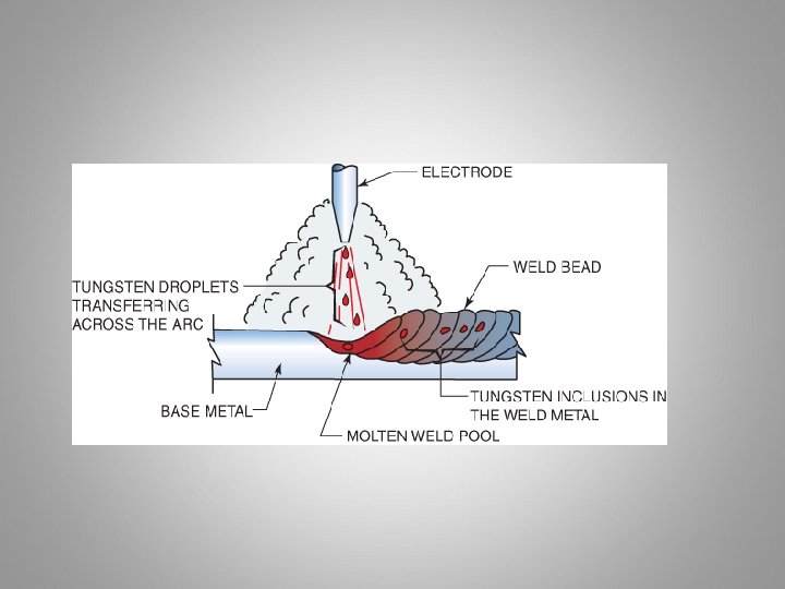
Tungsten (continued) • Tungsten is the best choice for a non consumable electrode – High melting temperature – Good electrical conductivity • As the tungsten electrode becomes hot the arc between the electrode and the work stabilizes – But a clean and correctly ground tungsten is needed • Because of the intense heat some erosion of the electrode will occur

Figure 15 -1 Some tungsten will erode and be transferred across the arc.
 • Ways to limit erosion: – Good mechanical and electrical contact –")
Tungsten (continued) • Ways to limit erosion: – Good mechanical and electrical contact – Use as low a current as possible – Use a water-cooled torch – Use as large a tungsten electrode as possible – Use DCEN current – Use as short an electrode extension as possible – Use the proper shape electrode – Use an alloyed tungsten electrode

Torch Build Out

Torch Build Out
 • The collet is the cone-shaped sleeve that holds the electrode in")
Tungsten (continued) • The collet is the cone-shaped sleeve that holds the electrode in the torch • Large-diameter electrodes conduct more current • The current-carrying capacity at DCEN is about ten times greater than at DCEP • The preferred electrode shape impacts the temperature and erosion of the tungsten • With alternating current, the tip is subjected to more heat than with DCEN

Figure 15 -3 The smooth surface of a centerless ground tungsten electrode. Courtesy of Larry Jeffus.

Types of Tungsten Electrodes • Pure tungsten is an excellent nonconsumable electrode • Pure tungsten can be improved by adding: – Cerium – Lanthanum – Thorium – Zirconium

Tungsten Electrodes

Table 15 -1 Tungsten Electrode Types and Identification.

Shaping the Tungsten • To obtain the desired end shape: – Grinding (for MS and SS) – Breaking (not recommended due to cost) – Re melting the end (Aluminium welding) – Using chemical compound (doesn’t work that well)

Grinding • Often used to clean a contaminated tungsten or to point the end • Should have a fine, hard stone – A coarse grinding stone with result in more tungsten breakage • Should be used for grinding tungsten only – Metal particles will quickly break free when the arc is started, causing contamination

Figure 15 -8 Correct way of holding a tungsten when grinding. Courtesy of Larry Jeffus.

Breaking and Remelting • Tungsten is hard but brittle – If struck sharply, it will break without bending – Try not to do this because of $$$$ • Holding against a sharp corner and hitting results in a square break • After breaking squarely, melt back the end

Chemical Cleaning and Pointing • Tungsten can be cleaned and pointed using one of several compounds • Heated by shorting it against the work • Dipped in the compound • When the tungsten is removed, cooled, and cleaned, the end will be tapered to a fine point • The chemical compound will dissolve the tungsten, allowing the contamination to fall free

Pointing and Remelting • Tapered tungsten with a balled end is made by first grinding or chemically pointing • The ball should be made large enough so that the color of the end stays dull red and bright red • Increase ball size by applying more current • Surface tension pulls the molten tungsten up onto the tapered end

Figure 15 -14 Melting the tungsten end shape.

GTAW Equipment

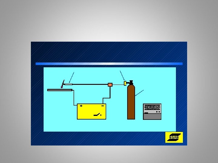
GTA Welding Equipment “Cadillac Stick Welder” • GTA welding torches are water- or air-cooled • Water-cooled GTA welding torch is more efficient • Water-cooled torch has three hoses connecting it to the welding machine • Nozzle directs the shielding gas directly on the welding zone • Flowmeter regulates the rate of gas flow

Figure 15 -21 Schematic of a GTA welding setup with a water-cooled torch.

Types of Welding Current • DCEN concentrates about 2/3 of its welding heat on the work – Max penetration – High Freq. – start only • DCEP concentrates about 1/3 of its welding heat on the work – Max cleaning action – 2/3 of heat at tungsten – primarily used for balling tungsten for aluminium welding – High Freq. – start only

Types of Welding Current • AC concentrates its heat at 50/50 – Sign wave provides for DCRP (cleaning action) and DCSP (penetration action) – Square wave technology allows for adjusting the cleaning or penetration cycle. – High Freq. is on Continuous so there is equal firing of both sides of sign wave. – DC Component will take place if there is no High Freq.

Figure 15 -29 Electrons collect under the oxide layer during the DCEP portion of the cycle.

Figure 15 -30 Sine wave of alternating current at 60 cycle.

Shielding Gas
 –")
Shielding Gases • Shielding gases used for GTA welding process: – Argon (Ar) – Helium (He) – Or a mixture of two or more gases
 • Argon effectively shields welds in deep grooves in flat positions")
Shielding Gases (continued) • Argon effectively shields welds in deep grooves in flat positions • Helium offers the advantage of deeper penetration
 • Hot start allows a surge of welding current • Preflow")
Shielding Gases (continued) • Hot start allows a surge of welding current • Preflow is the time gas flows to clear out air in the nozzle – Some machines do not have preflow • Postflow is the time the gas continues flowing after the welding current has stopped
 • Ionization Potential – Amount of voltage needed to “kick start”")
Shielding Gases (continued) • Ionization Potential – Amount of voltage needed to “kick start” the arc • The ionization potential, or ionization energy, of a gas atom is the energy required to strip it of an electron. That is why a shielding gas such as helium, with only 2 electrons in its outer shell, requires more energy (higher voltage parameters) for welding. The ionization potential of a shielding gas also establishes how easily an arc will initiate and stabilize. A low ionization potential means the arc will start relatively easy and stabilize quite well. A high ionization potential has difficulty initiating and may have difficulty keeping the arc stable. • Argon – 15. 7 electron volts • Helium – 24. 4 electron volts – More penetration

Figure 15 -35 Too steep an angle between the torch and work may draw in air.

Remote Controls Foot or Finger

Remote Controls • Can be used to: – Start the weld – Increase the current – Decrease the current – Stop the weld • Remote can be foot-operated or hand-operated device

Welding Techniques

Objectives • Applications using the gas tungsten arc welding process • Effects on the weld of varying torch angles • Why and how the filler rod is kept inside the protective zone of the shielding gas • How tungsten contamination occurs and what to do • Causes of change in welding amperage • Correct settings for the minimum and maximum welding current
 • Types and sizes of tungsten and metal • Factors affecting gas")
Objectives (continued) • Types and sizes of tungsten and metal • Factors affecting gas preflow and postflow times • Minimum and maximum gas flow settings: – Nozzle size – Tungsten size – Amperage setting • Characteristics of low carbon and mild steels, stainless steel, and aluminum • Metal preparation for GTA welding • Make GTA welds in all positions

Introduction • Gas tungsten arc is also called GTA welding • GTA welding can be used to for nearly all types and thicknesses of metal • GTA welding is fluxless, slagless, and smokeless • Welders have fine control of the welding process • GTA welding is ideal for close-tolerance welds • Some GTA welds make the critical root pass • GTA used when appearance is important
 • Setup of GTA equipment affects weld quality – Charts give correct")
Introduction (continued) • Setup of GTA equipment affects weld quality – Charts give correct settings • Field conditions affect the variables in the charts • Experiments designed to evaluate the appearance of a weld • After welding in the lab, troubleshooting field welding problems is easier • To make a weld is good: to solve a welding problem is better

Torch Angle • As close to perpendicular as possible • May be angled 0 -15 degrees from perpendicular for better visibility • As the gas flows out it forms a protective zone around the weld • Too much tilt distorts protective shielding gas zone

Figure 16 -5 Filler being remelted as the weld is continued. Courtesy of Larry Jeffus.
 • Velocity of shielding gas affects protective zone • Low-pressure area")
Torch Angle (continued) • Velocity of shielding gas affects protective zone • Low-pressure area develops behind the cup when velocity increases • Sharper angle and higher flow rate increases contamination

Filler Rod Manipulation • Filler rod must be kept inside the protective zone • If filler rod is removed from the gas protection, it oxidizes rapidly – Oxide is added to the molten weld pool • When a weld is temporarily stopped, the shielding gas must be kept flowing
 • If the rod tip becomes oxidized, if should be")
Filler Rod Manipulation (continued) • If the rod tip becomes oxidized, if should be cut off before restarting • The rod should enter the shielding gas as close to the base metal as possible • An angle less than 15 degrees prevents air from being pulled in the welding zone

Figure 16 -2 The hot filler rod end is well within the protective gas envelope. Courtesy of Larry Jeffus.

Figure 16 -7 Too much filler rod angle has caused oxides to be formed on the filler rod end. Courtesy of Larry Jeffus.

Tungsten Contamination • Most frequent problem is tungsten contamination • Tungsten becomes contaminated if it touches: – Molten weld pool – Filler metal • Surface tension pulls the contamination up onto the hot tungsten • Extreme heat causes some of the metal to vaporize and form a large oxide layer
 • Contamination caused by the tungsten touching the molten pool or")
Tungsten Contamination (continued) • Contamination caused by the tungsten touching the molten pool or filler metal forms a weak weld • The weld and tungsten must be cleaned before any more welding can be done • Tiny tungsten particles will show up if the weld is x-rayed • Contamination can be knocked off quickly by flipping the torch head • This procedure should never be used with heavy contamination or in the field

Figure 16 -8 Contaminated tungsten. Courtesy of Larry Jeffus.

Current Setting • Amperage on the machine's control is the same at the arc when: – Power to the machine is exactly correct – Lead length is very short – All cable connections are perfect – Arc length is exactly right – Remote current control is in the full on position

Figure 16 -10 Melting first occurring. Courtesy of Larry Jeffus.

Figure 16 -12 Oxides forming due to inadequate gas shielding. Courtesy of Larry Jeffus.

Gas Flow • Gas preflow and postflow times depend upon: – Wind or draft speed – Tungsten size used – Amperage – Joint design – Welding position – Type of metal welded • Maximum flow rates must never be exceeded – Air can be sucked into the weld zone

Practice Welds • Practice welds are grouped according to the weld position and type of joint • Mild steel is inexpensive and requires the least amount of cleaning • With aluminum, cleanliness is a critical factor • Try each weld with each metal to determine which metal will be easier to master

Low Carbon and Mild Steels • Low carbon and mild steel are two basic steel classifications • Small pockets of primary carbon dioxide gas become trapped • Porosity most likely when not using a filler metal • Most filler metals have some alloys, called deoxidizers

Stainless Steel • Setup and manipulation are nearly the same as for low carbon and mild steels • Most welds on stainless steels show effects of contamination • Most common problem is the bead color after the weld • Using a low arc current with faster travel speeds is important

Aluminum • Molten aluminum weld pool has high surface tension • Preheat the base metal in thick sections • Preheat temperature is around 300° Fahrenheit • Cleaning and keeping the metal clean is time consuming • Aluminum rapidly oxidizes at welding temperatures

Metal Preparation • Base and filler metals must be thoroughly cleaned • Contamination will be deposited into the weld • Oxides, oil, and dirt are the most common • Contaminants can be removed mechanically or chemically

Figure 16 -15 Aluminum filler being correctly added to the molten weld pool. Courtesy of Larry Jeffus.

Figure 16 -16 Filler rod being melted before it is added to the molten pool. Courtesy of Larry Jeffus.

Figure 16 -18 Surfacing weld. Courtesy of Larry Jeffus.

Figure 16 -20 Establish a molten weld pool and dip the filler rod into it. Courtesy of Larry Jeffus.

Figure 16 -21 Note the difference in the weld produced when different size filler rods are used. Courtesy of Larry Jeffus.

Figure 16 -22 Move the electrode back as the filler rod is added. Courtesy of Larry Jeffus.

Figure 16 -34 Be sure both the top and bottom pieces are melted. Courtesy of Larry Jeffus.

Figure 16 -35 Oxides form during tack welding. Courtesy of Larry Jeffus.

Figure 16 -36 A notch indicates the root was not properly melted and fused. Courtesy of Larry Jeffus.

Figure 16 -37 Watch the leading edge of the molten weld pool. Courtesy of Larry Jeffus.

Summary • Positioning yourself to control the electrode filler metal and to see the joint is critical • Experienced welders realize they need to see only the leading edge of the weld pool • Good idea to gradually reduce your need for seeing 100% of the weld pool – Increasing this skill is significant advantage in the field • Welding in the field may have to be done out of position
- Slides: 78