Gas Processing I NGT 140 Chapter 8 NGL


")


- Slides: 29
Gas Processing I NGT 140 Chapter 8 NGL Recovery – Cryogenic “This product was funded by a grant awarded by the U. S. Department of Labor’s Employment and Training Administration. The product was created by the grantee and does not necessarily reflect the official position of the U. S. Department of Labor. The Department of Labor makes no guarantees, warranties, or assurances of any kind, express or implied, with respect to such information, including any information on linked sites and including, but not limited to, accuracy of the information or its completeness, timeliness, usefulness, adequacy, continued availability, or ownership. ” Unless otherwise specified, this work by Shale. NET U. S. is licensed under a Creative Commons Attribution 4. 0 International License.
Ch 3 Ch 5 Ch 2 Ch 7 & 8 Ch 4 Ch 10 Ch 6 Ch 9 Ch 2 Ch 9
Chapter 7 presents the older, but still commonly used, lean oil absorption process. (Review) Chapter 8 covers the newer processes of refrigeration and turboexpansion.
Natural Gas Liquid’s • Are heavier hydrocarbons like butane and propane. • Often need to be removed to: – Reduce hydrocarbon dew point – Control gas heating value – Recover as a valuable source of income • History is complex – Simple lean oil absorption process replaced by addition of refrigeration • Chapter 7 – lean oil absorption • Refrigerated oil absorption – Modified ambient process to operate at lower temperature – Allowed use of lower molecular weight oils – Which can absorb more NGL’s • Cryogenic expander process when temperatures below -150 degrees F
History • Lean oil absorption common until the early 1970’s • Refrigerated oil absorption process introduced in 1957 • Major shift occurred in 1964 when low-temperature expander plant was built • Note: large cryogenics plants were an outgrowth of the US missile and rocket programs of the 1950’s which required large amounts of liquid oxygen (the 1 st ICBM Atlas using LOX and Kerosene) and later liquid hydrogen (Centaur upper stage was the first all cryogenic rocket using LOX and LH 2) • Cryogenic expander plants now dominate the market for NGL recovery
Transition to Refrigeration
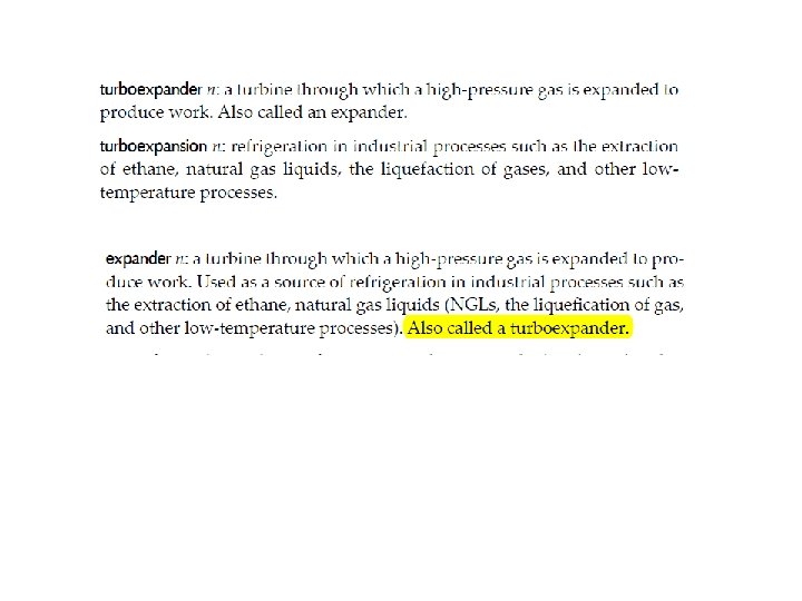
Turboexpander Process • Most widely used for the recovery of ethane and propane from natural gas • Also used to recover mechanical power from expanding processing streams • Also used in production of – Liquid helium – Liquid hydrogen – Liquefied natural gas (LNG)
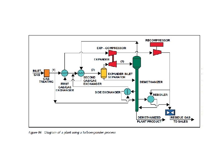
Process Combination of turboexpander – compressor • • Remove impurities that freeze (water, CO 2, etc) • Heat exchanger used cold residue gas to pre-cool the inlet gas stream • If gas stream is rich in NGL’s external refrigeration is used to supplement • Gas stream is split to maximize cooling – Gas/gas heat exchanger – Demethanizer side exchanger (source of cold liquid) • Helps cool the inlet gas • Source of added heat to vaporize methane in demethanizer • Gas stream combines to pass through second gas/gas heat exchanger – Condensed liquid removed by inlet separator (fed to demethanizer) • Vapor flows through the expander (pressure reduction) then to top section of demethanizer (serves as scrubber) • Residue gas is compressed and passed to sales
Turboexpander Process
Technology Drivers • Significant increase in the value of liquid ethane in the 1970’s • Technological improvements in the manufacture of practical turboexpanders (Space Program) • Compact and efficient plate-fin or brazed aluminum heat exchangers • Recompression requirements (25% - 50% of the plant cost) can be reduced by increasing the operating pressure of the demethanizer
Turboexpanders • 250 -20, 000 HP expanders • Drive the compressor with the turboexpander • Packaged units
Turboexpander-Compressor
Radial-reaction turbine • Nozzle blades can be tilted to vary the clearance between them • This adjusts the flow of gas into the rotor
Turboexpander Previous slide
Operating Considerations • Operate turboexpander at lowest possible temperature – results in condensation of liquid within the turboexpander • Turboexpander must operate over a wide speed range especially during start up • Variable speed implies the need for rigid shaft (stiff-shaft) design (see next slide) – Avoid critical shaft speed (resonance) – Applies to bearings as well (dictates large diameter shaft)
Wheel Shaft
Magnetic Bearings • Magnetic bearings with high loads are considered state -of-the-art at the present time • Contribute to the 98% reliability of existing turboexpander operations • Advantages – – Increased mechanical efficiency (1 -2%) No lubrication oils Reduced weight and size of skid Bearings can be cooled with process gas • Disadvantages – Bearings are large – Less stiff than conventional oil bearings
Active Magnetic Bearings
http: //en. wikipedia. org/wiki/Magnetic_bearing
Cryogenics – Heat Exchangers • Below -50 ⁰F shell and tube heat exchanger is less economical compared to plate fin (core) heat exchangers • 300 -400 sq ft of heat transfer surface per cubic foot of exchanger (6 -8 times the surface area of typical shell and tube exchanger) • 25 times more surface area per lb of equipment • Aluminum (alloys) used which have large thermal expansion and can suffer fatigue cracking • Parallel or cross flow designs depending on design of the header • Typical designs shown in final slides
Core of an Aluminum Plate
Corrugated Fin Flow Patterns
Cores of Plate-fin heat exchanger
Components of Brazed aluminum heat exchanger
Cryogenic Process
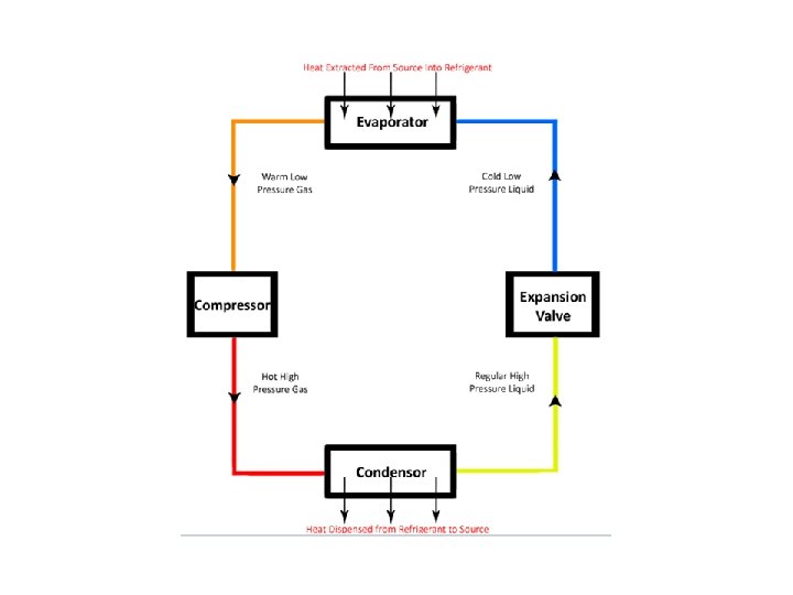
Refrigeration System • Operates through the continuous circulation of a refrigerant in a four-step cycle. 1. Expansion 2. Evaporation 3. Compression 4. Condensation • Operates much like a home air conditioner • Hot air blows across the evaporator causing the refrigerant to vaporize.