Gas Chromatography Lecture 36 1 Gas chromatography is


- Slides: 117

Gas Chromatography Lecture 36 1

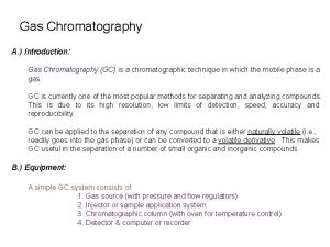
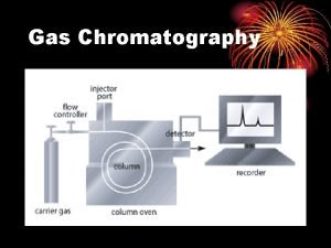
Gas chromatography is a technique used for separation of volatile substances, or substances that can be made volatile, from one another in a gaseous mixture at high temperatures. A sample containing the materials to be separated is injected into the gas chromatograph. A mobile phase (carrier gas) moves through a column that contains a wall coated or granular solid coated stationary phase. As the carrier gas flows through the column, the components of the sample come in contact with the stationary phase. The different components of the sample have different affinities for the stationary phase, which results in differential migration of solutes, thus leading to separation 2

Martin and James introduced this separation technique in 1952, which is the latest of the major chromatograhpic techniques. However, by 1965 over 18000 publications in gas chromatography (GC) were available in the literature. This is because optimized instrumentation was feasible. Gas chromatography is good only for volatile compounds or those, which can be made volatile by suitable derivatization methods or pyrolysis. Thus, about 20% of chemicals available can be analyzed directly by GC. 3

Gas chromatography can be used for both qualitative and quantitative analysis. Comparison of retention times can be used to identify materials in the sample by comparing retention times of peaks in a sample to retention times for standards. The same limitations for qualitative analysis discussed in Chapter 26 also apply for separations in GC. Quantitative analysis is accomplished by measurement of either peak height or peak area 4

Gas - Solid Chromatography (GSC) The stationary phase, in this case, is a solid like silica or alumina. It is the affinity of solutes towards adsorption onto the stationary phase which determines, in part, the retention time. The mobile phase is, of course, a suitable carrier gas. This gas chromatographic technique is most useful for the separation and analysis of gases like CH 4, CO 2, CO, . . . etc. The use of GSC in practice is considered marginal when compared to gas liquid chromatography. 5

Gas - Liquid Chromatography (GLC) The stationary phase is a liquid with very low volatility while the mobile phase is a suitable carrier gas. GLC is the most widely used technique for separation of volatile species. The presence of a wide variety of stationary phases with contrasting selectivities and easy column preparation add to the assets of GLC or simply GC. 6

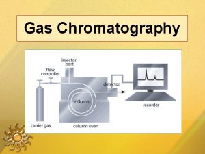
Instrumentation It may be wise to introduce instrumental components before proceeding further in theoretical background. This will help clarify many points, which may, otherwise, seem vague. It should also be noted that a detector will require special gas cylinders depending on the detector type utilized. The column temperature controller is simply an oven, the temperature of which can be varied or programmed 7

To Waste or Flow Meter Two-Stage Regulator Syringe Detector Injector Flow Controller Carrier Gas Cylinder 8 Column

9

Three temperature zones can be identified: 1. Injector temperature, TI, where TI should allow flash vaporization of all sample components. 2. Column temperature, Tc, which is adjusted as the average boiling points of sample components. 3. Detector Temperature, TD, which should exclude any possible condensation inside the detector. Generally, an intuitive equation can be used to adjust all three zones depending on the average boiling point of the sample components. This equation is formulated as: TI = TD = Tc + 50 o. C 10

The Carrier Gas Unlike liquid chromatography where wide varieties of mobile phase compositions are possible, mobile phases in gas chromatography are very limited. Only slight changes between carrier gases can be identified which places real limitations to chromatographic enhancement by change or modification of carrier gases 11

A carrier gas should have the following properties: 1. Highly pure (> 99. 9%) 2. Inert so that no reaction with stationary phase or instrumental components can take place, especially at high temperatures. 3. A higher density (larger viscosity) carrier gas is preferred. 4. Compatible with the detector since some detectors require the use of a specific carrier gas. 5. A cheap and available carrier gas is an advantage. 12

Longitudinal Diffusion Term This is an important factor contributing to band broadening which is a function of the diffusivity of the solute in the gaseous mobile phase as well as the molecular diffusion of the carrier gas itself. HL = K DM /V Where; DM is the diffusion coefficient of solute in the carrier gas. This term can be minimized when mobile phases of low diffusion, i. e. high density, are used in conjunction with higher flow rates. 13

The same van Deemter equation as in LC can be written for GC where: H = A + B/V + CV The optimum carrier gas velocity is given by the derivative of van Deemter equation Vopt = { B/C }1/2 However, the obtained velocity is much greater than that obtained in LC. 14

The carrier gas pressure ranges from 10 -50 psi. Higher pressures potentially increase compression possibility while very low pressures result in large band broadening due to diffusion. Depending on the column dimensions, flow rates from 1 -150 m. L/min are reported. Conventional analytical columns (1/8”) usually use flow rates in the range from 20 -50 m. L/min while capillary columns use flow rates from 1 -5 m. L/min depending on the dimensions and nature of column. In most cases, a selection between helium and nitrogen is made as these two gases are the most versatile and common carrier gases in GC. 15

Gas Chromatography Lecture 37 16

Injectors Septum type injectors are the most common. These are composed of a glass tube where vaporization of the sample takes place. The sample is introduced into the injector through a self-sealing silicone rubber septum. The carrier gas flows through the injector carrying vaporized solutes. The temperature of the injector should be adjusted so that flash vaporization of all solutes occurs. If the temperature of the injector is not high enough (at least 50 degrees above highest boiling component), band broadening will take place. 17

Syringe Septum Carrier Gas Vaporization Chamber To Column 18

19

20

21

22

23

24

25

Column Configurations and Ovens The column in chromatography is undoubtedly the heart of the technique. A column can either be a packed or open tubular. Traditionally, packed columns were most common but fast developments in open tubular techniques and reported advantages in terms of efficiency and speed may make open tubular columns the best choice in the near future. Packed columns are relatively short (~2 meters) while open tubular columns may be as long as 30 -100 meters 26

Packed columns are made of stainless steel or glass while open tubular columns are usually made of fused silica. The temperature of the column is adjusted so that it is close to the average boiling point of the sample mixture. However, temperature programming is used very often to achieve better separations. The temperature of the column is assumed to be the same as the oven which houses the column. The oven temperature should be stable and easily changed in order to obtain reproducible results. 27

Detection Systems Several detectors are available for use in GC. Each detector has its own characteristics and features as well as drawbacks. Properties of an ideal detector include: 28 1. 2. 3. 4. 5. 6. 7. 8. 9. High sensitivity Minimum drift Wide dynamic range Operational temperatures up to 400 o. C. Fast response time Same response factor for all solutes Good reliability (no fooling) Nondestructive Responds to all solutes (universal)

a. Thermal Conductivity Detector (TCD) This is a nondestructive detector which is used for the separation and collection of solutes to further perform some other experiments on each purely separated component. The heart of the detector is a heated filament which is cooled by helium carrier gas. Any solute passes across the filament will not cool it as much as helium does because helium has the highest thermal conductivity. This results in an increase in the temperature of the filament which is related to concentration. The detector is simple, nondestructive, and universal but is not very sensitive and is flow rate sensitive. 29

30

31

Note that gases should always be flowing through the detector including just before, and few minutes after, the operation of the detector. Otherwise, the filament will melt. Also, keep away any oxygen since oxygen will oxidize the filament and results in its destruction. 32 Remember that TCD characteristics include: 1. Rugged 2. Wide dynamic range (105) 3. Nondestructive 4. Insensitive (10 -8 g/s) 5. Flow rate sensitive

b. Flame Ionization Detector (FID) This is one of the most sensitive and reliable destructive detectors. Separate two gas cylinders, one for fuel and the other for O 2 or air are used in the ignition of the flame of the FID. The fuel is usually hydrogen gas. The flow rate of air and hydrogen should be carefully adjusted in order to successfully ignite the flame. 33

34

35

The FID detector is a mass sensitive detector where solutes are ionized in the flame and electrons emitted are attracted by a positive electrode, where a current is obtained. The FID detector is not responsive to air, water, carbon disulfide. This is an extremely important advantage where volatile solutes present in water matrix can be easily analyzed without any pretreatment. 36

Remember that FID characteristics include: • Rugged • Sensitive (10 -13 g/s) • Wide dynamic range (107) • Signal depends on number of carbon atoms in organic analytes which is referred to as mass sensitive rather than concentration sensitive • Weakly sensitive to carbonyl, amine, alcohol, amine groups • Not sensitive to non-combustibles – H 2 O, CO 2, SO 2, NOx • Destructive 37

Electron Capture Detector (ECD) This detector exhibits high intensity for halogen containing compounds and thus has found wide applications in the detection of pesticides and polychlorinated biphenyls. The mechanism of sensing relies on the fact that electronegative atoms, like halogens, will capture electrons from a b emitter (usually 63 Ni). In absence of halogenated compounds, a high current signal will be recorded due to high ionization of the carrier gas, which is N 2, while in presence of halogenated compounds the signal will decrease due to lower nitrogen ionization. 38

39

40

Remember the following facts about ECD: 1. Electrons from a b-source ionize the carrier gas (nitrogen) 2. Organic molecules containing electronegative atoms capture electrons and decrease current 3. Simple and reliable 4. Sensitive (10 -15 g/s) to electronegative groups (halogens) 5. Largely non-destructive 6. Insensitive to amines, alcohols and hydrocarbons 7. Limited dynamic range (102) 8. Mass sensitive detector 41

Gas Chromatography Lecture 38 42

Gas Chromatographic Columns and Stationary Phases Packed Columns These columns are fabricated from glass, stainless steel, copper, or other suitable tubes. Stainless steel is the most common tubing used with internal diameters from 1 -4 mm. The column is packed with finely divided particles (<100 -300 mm diameter), which is coated with stationary phase. However, glass tubes are also used for large-scale separations. 43

44

Several types of tubing were used ranging from copper, stainless steel, aluminum and glass. Stainless steel is the most widely used because it is most inert and easy to work with. The column diameters currently in use are ordinarily 1/16" to 1/4" 0. D. Columns exceeding 1/8" are usually used for preparative work while the 1/8" or narrower columns have excellent working properties and yield excellent results in the analytical range. These find excellent and wide use because of easy packing and good routine separation characteristics. Column length can be from few feet for packed columns to more than 100 ft for capillary columns. 45

46

Capillary/Open Tubular Open tubular or capillary columns are finding broad applications. These are mainly of two types: • Wall-coated open tubular (WCOT) <1 mm thick liquid coating on inside of silica tube • Support-coated open tubular (SCOT) 30 mm thick coating of liquid coated support on inside of silica tube These are used for fast and efficient separations but are good only for small samples. The most frequently used capillary column, nowadays, is the fused silica open tubular column (FSOT), which is a WCOT column. 47

The external surface of the fused silica columns is coated with a polyimide film to increase their strength. The most frequently used internal diameters occur in the range from 260 -320 micrometer. However, other larger diameters are known where a 530 micrometer fused silica open tubular column was recently made and is called a megapore column, to distinguish it from other capillary columns. Megapore columns tolerate a larger sample size. 48

49

50

51

52

53

It should be noted that since capillary columns are not packed with any solid support, but rather a very thin film of stationary phase which adheres to the internal surface of the tubing, the A term in the van Deemter equation which stands for multiple path effects is zero and the equation for capillary columns becomes H = B/V + CV 54

Capillary columns advantages compared to packed columns 1. higher resolution 2. shorter analysis times 3. greater sensitivity Capillary columns disadvantage compared to packed columns 1. smaller sample capacity 2. Need better experience 55

Solid Support Materials The solid support should ideally have the following properties: 1. Large surface area (at least 1 m 2/g) 2. Has a good mechanical stability 3. Thermally stable 4. Inert surface in order to simplify retention behavior and prevent solute adsorption 5. Has a particle size in the range from 100400 mm 56

Selection of Stationary Phases General properties of a good liquid stationary phase are easy to guess where inertness towards solutes is essential. Very low volatility liquids that have good absolute and differential solubilities for analytes are required for successful separations. An additional factor that influences the performance of a stationary phase is its thermal stability where a stationary phase should be thermally stable in order to obtain reproducible results. Nonvolatile liquids assure minimum bleeding of the stationary phase 57

Weight of liquid stationary phase * 100% %Loading = Weight of stationary phase plus solid support Increasing percent loading would allow for increased sample capacity and cover any active sites on the solid support. These two advantages are very important, however increasing the thickness of stationary phase will affect the C term in the van Deemter equation by increasing HS, and therefore Ht. 58

Generally, the film thickness primarily affects the retention character and the sample capacity of a column. Thick films are used with highly volatile analytes, because such films retain solutes for a longer time and thus provide a greater time for separation to take place. Thin films are useful for separating species of low volatility in a reasonable time. On the other hand, a thicker film can tolerate a larger sample size. Film thicknesses in the range from 0. 1 – 5 mm are common. 59

Liquid Stationary Phases In general, the polarity of the stationary phase should match that of the sample constituents ("like" dissolves "like"). Most stationary phases are based on polydimethylsiloxane or polyethylene glycol (PEG) backbones: 60

61

The polarity of the stationary phase can be changed by derivatization with different functional groups such as a phenyl group. Bleeding of the column is cured by bonding the stationary phase to the column; or crosslinking the stationary phase. 62 Liquid Stationary Phases should have the following characteristics: • Low volatility • High decomposition temperature (thermally stable) • Chemically inert (reversible interactions with solvent) • Chemically attached to support (to prevent bleeding) • Appropriate k' and a for good resolution

Bonded and Crosslinked Stationary Phases The purpose of bonding and cross-linking is to prevent bleeding and provide a stable stationary phase. With use at high temperatures, stationary phases that are not chemically bonded or crosslinked slowly lose their stationary phase due to bleeding in which a small amount of the physically immobilized liquid is carried out of the column during the elution process. Crosslinking is carried out in situ after a column is coated with one of the polymers 63

64

In summary, stationary phases are usually bonded and/or crosslinked and the following remarks are usually helpful: 1. Bonding occurs through covalent linking of stationary phase to support 2. Crosslinking occurs through polymerization reactions to join individual stationary phase molecules 3. Nonpolar stationary phases are best for nonpolar analytes where nonpolar analytes are retained preferentially 4. Polar stationary phases are best for polar analytes where polar analytes are retained preferentially 65

Gas Chromatography Lecture 39 66

Gas-liquid chromatography (GLC) Packed columns are fabricated from glass, metal, or Teflon with 1 to 3 m length and 2 to 4 mm in internal diameter. The column is packed with a solid support (100 -400 mm particle diameter made from diatomaceous earth) that has been coated with a thin layer (0. 1 -5 mm) of the stationary liquid phase. Efficiency increases with decreasing particle size as predicted from van Deemter equation. The retention is based on absorption of analyte (partition into the liquid stationary phase) where solutes must have differential solubility in the stationary phase 67

Open tubular capillary columns, either WCOT, SCOT are routinely used. In WCOT the capillary is coated with a thin film (0. 1 -0. 25 mm) of the liquid stationary phase while in SCOT a thin film of solid support material is first affixed to the inner surface of the column the support is coated with the stationary phase. WCOT columns are most widely used. Capillary columns are typically made from fused silica (FSOT) and are 15 to 100 m long with 0. 10 to 0. 5 mm i. d. 68

The thickness of the stationary phase affects the performance of the column as follows: 1. Increasing thickness of stationary phase allows the separation of larger sample sizes. 2. Increasing thickness of stationary phase reduces efficiency since HS increases. 3. Increasing thickness of stationary phase is better for separation of highly volatile compounds due to increased retention. • 69

Much more efficient separations can be achieved with capillary columns, as compared to packed columns, due to the following reasons: 1. Very long capillary columns can be used which increases efficiency 2. Thinner stationary phase films can be used with capillary columns 3. No eddy diffusion term (multiple paths effect) is observed in capillary columns 70

71

Temperature Programming Gas chromatographs are usually capable of performing what is known as temperature programming gas chromatography (TPGC). The temperature of the column is changed according to a preset temperature isotherm. TPGC is a very important procedure, which is used for the attainment of excellent looking chromatograms in the least time possible. For example, assume a chromatogram obtained using isothermal GC at 80 o. C, as shown below: 72

Isothermal at 45° Isothermal at 145° Programmed 30 to 180° 73

74

75

76

The General Elution Problem Look at the chromatogram below in which six components are to be separated by an elution process using isothermal conditions at for example 120 o. C: 77

It is clear from the figure that the separation is optimized for the elution of the first two components. However, the last two components have very long retention and appear as broad peaks. Using isothermal conditions at high temperature (say for example 200 o. C) can optimize the elution of the last two compounds but, unfortunately, results in bad resolution of the earlier eluting compounds as shown in the figure below where the first two components are coeluted while the resolution of the second two components becomes too bad: 78

79

One can also optimize the separation of the middle too components by adjusting the isothermal conditions (for example at say 160 o. C). In this case, a chromatogram like the one below can be obtained: 80

However, in chromatographic separations we are interested in fully separating all components in an acceptable resolution. Therefore, it is not acceptable to optimize the separation for a single component while disregarding the others. The solution of this problem can be achieved by consecutive optimization of individual components as the separation proceeds. In this case, temperature should be changed during the separation process. This is called temperature programming gas chromatography (TPGC) 81

First, a temperature suitable for the separation of the first eluting component is selected, and then the temperature is increased so that the second component is separated and so on. The change in temperature can be linear, parabolic, step, or any other formula. The chromatographic separation where the temperature is changed during the elution process is called TPGC. A separation like the one below can be obtained: 82

83

Temperature Zones in GC Three temperature zones should be adjusted before a GC separation can be done. The injector temperature should be such that fast evaporation of all sample components is achieved. The temperature of the injector is always more than that of the column, which depends on the operational mode of the separation. The detector temperature should be kept at some level so as to prevent any solute condensation in the vicinity of the detector body. 84

Gas-solid chromatography (GSC) Gas-solid chromatography is based upon adsorption of gaseous substances on solid surfaces. Distribution coefficients are generally much larger than those for gasliquid chromatography. Consequently, gassolid chromatography is useful for the separation of species that are not retained by gas-liquid columns, such as the components of air, hydrogen sulfide, carbon disulfide, nitrogen oxides, and rare gases. Gas-solid chromatography is performed with both packed and open tubular columns. 85

Molecular Sieves Molecular sieves are metal aluminum silicate ion exchangers, whose pore size depends upon the kind of cation present, like sodium in sodium aluminum silicate molecular sieves. The sieves are classified according to the maximum diameter of molecules that can enter the pores. Commercial molecular sieves come in pore sizes of 4, 5, 10, and 13 angstroms. Molecular sieves can be used to separate small molecules from large ones. 86

Porous Polymers Porous polymer beads of uniform size are manufactured from styrene crosslinked with divinylbenzene. The pore size of these beads is uniform and is controlled by the amount of crosslinking. Porous polymers have found considerable use in the separation of gaseous species such as hydrogen sulfide, oxides of nitrogen, water, carbon dioxide, methanol, etc. 87

Quantitative Analysis GC is an excellent quantitative technique where peak height or area is proportional to analyte concentration. Thus the GC can be calibrated with several standards and a calibration curve is obtained, then the concentration of the unknown analyte can be determined using the peak area or height. The detector response factor for each analyte should be considered for accurate quantitative analysis. 88

Gas chromatographs are widely used as criteria for establishing the purity of organic compounds. Contaminants, if present, are revealed by the appearance of additional peaks. Qualitative Analysis is usually done by comparison with retention times of standards, which are very reproducible in GC, provided good injection practices are followed. Injection should be done with a suitable Hamilton type syringe through the heated septum injector till all needle disappears, then the needle is drawn back as steadily and fast as possible. This is important for reproducible attainment of retention times. 89

The Retention Index The retention index, RI, was first proposed by Kovats in 1958 as a parameter for identifying solutes from chromatograms. The retention index for any given solute can be derived from a chromatogram of a mixture of that solute with at least two normal alkanes (chain length >four carbons) having retention times that bracket that of the solute. That is, normal alkanes are the standards upon which the retention index scale is based. 90

By definition, the retention index for a normal alkane is equal to 100 times the number of carbons in the compound regardless of the column packing, the temperature, or other chromatographic conditions. The retention index system has the advantage of being based upon readily available reference materials that cover a wide boiling range. The retention index of a compound is constant for a certain stationary phase but can be totally different for other stationary phases. 91

In finding the retention index, a plot of the number of carbons of standard alkanes against the logarithm of the adjusted retention time is first constructed. The value of the logarithm of the adjusted retention time of the unknown is then calculated and the retention index is obtained from the plot. The adjusted retention time, t. R’, is defined as: t 92 R’ = t. R - t. M

93

Interfacing GC with other Methods As mentioned previously, chromatographic methods (including GC) use retention times as markers for qualitative analysis. However, this characteristic does not absolutely confirm the existence of a specific analyte as many analytes may have very similar stationary phases. GC, as other chromatographic techniques, can confirm the absence of a solute rather than its existence. When GC is coupled with structural detection methods, it serves as a powerful tool for identifying the components of complex mixtures. A popular combination is GC/MS. 94

95

Mass Spectrometry Analytical method to measure the molecular or atomic weight of samples 96

Different elements can be uniquely identified by their masses 97

MS Principles Different compounds can be uniquely identified by their masses Butorphanol L-dopa N -CH 2 OH Ethanol COOH HO -CH 2 CH-NH 2 CH 3 CH 2 OH HO HO MW = 327. 1 98 MW = 197. 2 MW = 46. 1

Mass Spectrometry • For small organic molecules the MW can be determined to within 5 ppm or 0. 0005% which is sufficiently accurate to confirm the molecular formula from mass alone • For large biomolecules the MW can be determined within 0. 01% (i. e. within 5 Da for a 50 k. D protein) • Recall 1 dalton = 1 atomic mass unit (1 amu) 99

MS Principles • Find a way to “charge” an atom or molecule (ionization) • Place charged atom or molecule in a magnetic field or subject it to an electric field and measure its speed or radius of curvature relative to its mass-to-charge ratio (mass analyzer) • Detect ions using microchannel plate or electron multiplier tube 100

Mass Spectrometer Schematic Rough pumps Rotary pumps Turbo pumps Diffusion pumps High Vacuum System Inlet Vapor HPLC GC Solids probe 101 Ion Source MALDI ESI FAB EI/CI Mass Filter TOF Quadrupole Ion Trap Mag. Sector FTMS Detector Microch plate Electron Mult. Data System PC’s UNIX Mac

Mass Spec Principles Sample + _ Ionizer 102 Mass Analyzer Detector

Typical Mass Spectrum • Characterized by sharp, narrow peaks • X-axis position indicates the m/z ratio of a given ion (for singly charged ions this corresponds to the mass of the ion • Height of peak indicates the relative abundance of a given ion (not reliable for quantitation) • Peak intensity indicates the ion’s ability to desorb or “fly” (some fly better than others) 103

A Typical Mass Spectrum O H 3 C C N Mass Spectrometer CH C O C H 3 C N H N Typical sample: isolated compound (~1 nanogram) 194 Mass Spectrum Abundance 67 109 55 82 42 136 94 104 40 60 80 100 120 Mass (amu) 140 165 160 180 200

105

106

Electron Impact Ionization Source Electron Collector (Trap) Positive Ions Neutral Molecules Repeller + + + e- e- e_ Filament 107 Inlet + _ _ + + to + + Analyzer Electrons Extraction Plate

Mass Spectrometer Schematic Rough pumps Rotary pumps Turbo pumps Diffusion pumps High Vacuum System Inlet Vapor HPLC GC Solids probe 108 Ion Source MALDI ESI FAB EI/CI Mass Filter TOF Quadrupole Ion Trap Mag. Sector FTMS Detector Microch plate Electron Mult. Data System PC’s UNIX Mac

Magnetic Sector Mass Analyzer ion trajectory in register ion trajectory not in register (too light) S Ion Source Detector N Electromagnet 109 ion trajectory not in register (too heavy)

Quadrupole Mass Analyzer • A quadrupole mass filter consists of four parallel metal rods with different charges • The applied voltages affect the trajectory of ions traveling down the flight path • For given dc and ac voltages, only ions of a certain mass-to-charge ratio pass through the quadrupole filter and all other ions are thrown out of their original path 110

Quadrupole Ion Filter resonant ion non-resonant ion _ Detector + _ + Ion Source DC and AC Voltages 111

Mass Spectrometer Schematic Rough pumps Rotary pumps Turbo pumps Diffusion pumps High Vacuum System Inlet Vapor HPLC GC Solids probe 112 Ion Source MALDI ESI FAB EI/CI Mass Filter TOF Quadrupole Ion Trap Mag. Sector FTMS Detector Microch plate Electron Mult. Data System PC’s UNIX Mac

MS Detectors • Early detectors used photographic film • Today’s detectors (ion channel and electron multipliers) produce electronic signals via 2 ry electronic emission when struck by an ion • Timing mechanisms integrate these signals with scanning voltages to allow the instrument to report which m/z has struck the detector • Need constant and regular calibration 113

Mass Detectors Electron Multiplier 114

115

116

Club Drugs 1. 2. 3. 4. 5. 6. 7. 8. 9. 10. 11. Methamphetamine (0. 18 mg/m. L) 4 -Methoxyamphetamine (0. 18 mg/m. L) 2, 3 -MDA (0. 18 mg/m. L) 3, 4 -MDA (0. 18 mg/m. L) 2, 3 -MDMA (0. 18 mg/m. L) 3, 4 -MDMA (0. 18 mg/m. L) 4 -Bromo-2, 5 -dimethoxyphenethylamine (0. 18 mg/m. L) Ketamine (0. 18 mg/m. L) Phencyclidine (0. 18 mg/m. L) Cocaine (0. 18 mg/m. L) Flunitazepam (0. 18 mg/m. L) Column: Column Temp: Carrier Gas: Detector: 117 Heliflex® AT™-1 ms 30 m x 0. 25 mm x 0. 25µm (Part No. 15897) 140°C (1 min hold) to 300°C (3 min hold) at 10°C/min Helium at 0. 8 m. L/min (24 cm/sec) FID at 340 °C
 01:640:244 lecture notes - lecture 15: plat, idah, farad
 Introduction of chromatography
 Introduction to chromatography
 Percent composition gas chromatography
 Paper chromatography polarity
 Principles of gc
 Hplc slideshare
 Mobile phase in chromatography
 Gas chromatography
 Basic principle of gas chromatography
 Gas chromatography theory
 Basic gas chromatography
 équation van deemter
 Gas chromatography
 Perhitungan rf pada klt
 Gas liquid chromatography
 Gas chromatography history
 Difference between isocratic and gradient elution
 Gas chromatography
 Poisonous gas leaked in bhopal gas tragedy
 Gas exchange key events in gas exchange
 An ideal gas is an imaginary gas
 Gas leaked in bhopal gas tragedy
 Difference between ideal gas and real gas
 Differences between ideal gas and real gas
 Gas reale e gas ideale
 Reaksi pembentukan gas no2f dari gas no2 dan f2
 Computational fluid dynamics
 Flue gas desulfurisation gas filter
 Derive ideal gas equation
 Conclusion of bhopal gas tragedy
 Om306
Om306 Classical mechanics
 Productive skills
 Environmental sociology lecture notes
 Floor of femoral triangle
 Bayesian classification in data mining lecture notes
 Membership function fuzzy logic
 Scotch tape preparation for fungi
 Project management lecture
 Project management for software development
 Outline of sociology
 Drawing lecture
 Network management principles and practice
 In this lecture
 Abaque de lecture hématocrite
 La lecture renoir
 Wbb99
Wbb99 Erp in supply chain management ppt
 Lecture about money
 Tensorflow lecture
 Diapedesis
 Lecture 19
 Data mining lecture notes
 Real estate lecture
 Harvard referencing lecture
 L'histoire du friauche
 Mass spectrometry lecture
 Lecture au quotidien
 Land use planning '' lecture notes
 Nus lecture
 Lecture collocations
 Human resource management lecture chapter 1
 Bmfp
Bmfp Social business letter example
 Computer-aided drug design lecture notes
 Andrew ng machine learning slides
 Fiche de lecture master
 Tirez pas sur le scarabée résumé par chapitre
 Bjt
Bjt Watershed segmentation
 Er diagram ppt
 Anderson localization lecture notes
 Lecture à l'unisson
 What is farsightedness called
 Jean baptiste perrin nobel prize
 According to walter pauk, 10 weeks after lecture
 Micropaleontology lecture notes
 Lecture title
 Physics 101 lecture notes pdf
 Operating system lecture notes
 Epiploic foramen boundaries
 Foundation engineering lecture notes
 Lecture on love courtship and marriage
 Linear regression lecture
 Image processing lecture notes
 Emf equation of a transformer
 Ethem alpaydin
 Banking and finance lecture
 Natural language processing
 Dcac lecture series
 Ideal diode definition
 What does reverend cram want the iroquois to do?
 Comprhension
 Othello lecture
 Streak plate method
 Social psychology lecture
 Land use planning '' lecture notes
 Sltpttch
 Physics 101 lecture 1
 Transformer lecture
 Fuzzy logic lecture
 Grille de lecture systémique
 Lecture collocations
 In this lecture
 Microwave remote sensing lecture notes
 Slagle lecture
 Existential nihilism
 Idsat equation
 Frozenness meaning
 Lecture 8
 Power system dynamics and stability lecture notes
 Semiconductor lecture
 C data types with examples
 Hplc lecture
 Medical ethics lecture
 Orf in bioinformatics
 Nutritive value of watermelon
