Garmin 330 Mode S Transponder Cirrus Transition Course


- Slides: 13

Garmin 330 Mode S Transponder Cirrus Transition Course 08/18/04

The system information, procedures and guidelines found in this presentation are for Reference Only. The information & procedures in this presentation have been taken from the FAA Approved Airplane Flight Manual and Pilot’s Operating Handbook (POH). The Information & Procedures in this presentation DO NOT SUPERSEDE the Information & Procedures in the POH. In the event of conflict, the POH shall take precedence.

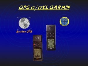
The Garmin GTX 330 transponder system consists of an integrated receiver/transmitter control unit, an antenna, and an altitude digitizer (encoder). In addition to displaying the code, reply symbol, and mode of operation, the GTX 330 displays pressure altitude. The unit also features an altitude monitor and flight timers. Depending on how the transponder is configured (factory set to voice), a voice or tone audio output announces altitude deviation of more than 200 feet and count down timer expiration.

Expected coverage from the GTX 330 is limited to “line of sight. ” Low altitude or aircraft antenna shielding by the airplane itself may result in reduced range. Range can be improved by climbing to a higher altitude.

How TCAS (Skywatch) differs from TIS (Mode S) – Main difference between TCAS (Traffic Collision Avoidance System) and TIS (Traffic Information System) is the source of surveillance. TCAS uses an airborne interrogator with a half second update rate, while TIS uses the terminal Mode S ground interrogator and its datalink to provide a 5 second update rate. The TIS Display on the Garmin 430’s will show up to 8 traffic targets within 7. 5 nm from 3000 ft below to 3500 ft above the requesting aircraft. TIS Information is not intended to be used as collision avoidance

Controls and Functions ON Key - Powers on the GTX 330 in Mode A (identification mode. ). The last active identification code will be selected. In addition to the airplane’s identification code, the transponder will also reply to altitude (Mode C) interrogations with signals that do not contain altitude information. STBY Key - Powers the transponder in standby mode. The last active identification code will be selected. The transponder will not reply to any interrogations. STBY mode is automatically entered from ALT or ON mode during landing ground roll as the groundspeed decreases through 35 knots. OFF Key - Turns off all power to the GTX 330 transponder. The transponder should be off until the engine is started. Normally, the transponder can be left in the STBY position and allow the Avionics Power Switch to control system power.

Controls and Functions ALT Key - Places the transponder in Mode C. The last active identification code will be selected. The transponder will respond to interrogations. ALT mode is automatically entered from STBY mode during takeoff ground roll as the groundspeed increases through 35 kts. IDENT Key - Pressing the IDENT button activates the Special Position Identification (SPI) pulse for approximately 18 seconds allowing ATC to identify your transponder return from other returns on the controller’s scope. The Reply annunciator in the display will illuminate during the SPI pulse. VFR Key - Pressing the VFR key sets the transponder to the pre-programmed VFR code factory set to 1200. Pressing the VFR key a second time will restore the previous identification code.

Controls and Functions FUNC Key - Pressing the FUNC key changes the data shown on the right side of the display. Pressing the FUNC key a second time will cycle the display to the next data. Displayed data includes Pressure Altitude, Flight Time, Count Up Timer, Count Down Timer, Contrast, and Display Brightness. START/STOP Key - Starts and stops the Altitude Monitor, Count Up, Count Down, and Flight timers. In Configuration Mode, steps through functions in reverse. CRSR Key - Initiates starting time entry for the Count Down timer. Returns cursor to last code digit within five seconds after entry. Selects changeable fields in Configuration Mode. CLRL Key - Resets the Count Up, Count Down, and Flight timers. Cancels the previous keypress during code selection and Count Down entry. Returns cursor to the fourth code digit within five seconds after entry.

Controls and Functions Function Displays PRESSURE ALT - Displays pressure altitude in feet. An arrow to the right of the altitude indicates that the airplane is climbing or descending. FLIGHT TIME - Displays the flight time. The timer receives groundspeed from GPS 1. Flight time starts when the groundspeed reaches 35 knots on takeoff and pauses when the groundspeed descends below 35 knots on landing. ALT MONITOR - Controlled by START / STOP key. Activates a voice alarm when altitude limit is exceeded COUNT UP TIMER - The count up timer is controlled by the START / STOP key. Pressing the CLR key zeros the display. COUNT DOWN TIMER - The count down timer is controlled by the START / STOP key. The CRSR and “ 0 - 9” keys are used to set the initial time. Pressing the CLR key resets the timer to the initial value. DISPLAY - The display function is not available in this installation. Display brightness is automatically controlled through a photocell in the front panel.

When making routine code changes, avoid inadvertent selection of code 7500 and all codes within the 7600 series (7600 – 7677) and 7700 series (7700 – 7777). These codes trigger special indicators in automated facilities. 7500 will be decoded as the hijack code. Important Codes 1200 – VFR code for any altitude in U. S. 7000 – VFR code commonly used in Europe 7500 – Hijacking 7600 – Loss of communications 7700 – Emergency 7777 – Military interceptor operations (Never squawk this code) 0000 – Military use only (Not enterable)

Modes Coverage Map

Normal Procedures After Engine Start Avionics Power Switch. . . . ON The transponder will turn on in the same mode of operation selected at the last power down and will display the last entered identification code. Before Takeoff Transponder Mode Selector Keys. . . . ALT If the transponder is in STBY or GND mode, it will automatically switch to ALT during takeoff when the groundspeed increases through approximately 35 knots. The transponder will respond to ATC Mode A/C (altitude and identification) interrogations. Note, Selecting ON puts the transponder in Mode A/S only. The transponder will respond to Mode C (altitude) interrogations with signals that contain no altitude information.

Normal Procedures After Landing Transponder Mode Selector Keys. . . STBY or OFF If the transponder is in the ALT or ON mode for landing, and the airplane is in a Mode S environment, the transponder will automatically switch to GND during landing rollout when the groundspeed decreases through approximately 35 knots. If the airplane is not in a Mode S environment, the transponder will automatically switch to STBY during landing rollout.

