Gaits Cost of Transportation Wheeled Mobile Robots Most

Gaits

Cost of Transportation

Wheeled Mobile Robots • • • Most popular locomotion mechanism Highly efficient Simple mechanical implementation Balancing is not usually a problem Suspension system needed to allow all wheels to maintain ground contact on uneven terrain

Wheeled Mobile Robots • Focus is on – Traction – Stability – Maneuverability – Control
 Standard wheels – 2 DOF b) Castor wheels – 2 DOF")
Wheel Designs a) Standard wheels – 2 DOF b) Castor wheels – 2 DOF
 Swedish (Omni) wheels – 3 DOF d) Ball or spherical wheel")
Wheel Designs c) Swedish (Omni) wheels – 3 DOF d) Ball or spherical wheel – 3 DOF – Think mouse ball – Suspension issue

Wheeled Mobile Robots • Stability of a vehicle is guaranteed with 3 wheel – center of gravity is within the triangle formed by ground contact points of wheels • Stability is improved by 4 and more wheels • Bigger wheels allow to overcome higher obstacles – But require higher torque or reductions in the gear box • Most arrangements are non-holonomic – require high control effort • Combining actuation and steering on one wheel makes design complex and adds additional errors for odometry

Static Stability with Two Wheels • Achieved by ensuring center of mass is below wheel axis • Or using fancy balancing

Motion Control • Kinematic/dynamic model of the robot • Model the interaction between wheel and ground • Definition of required motion – Speed control – Position control • Control law that satisfies the requirements

Mobile Robot Kinematics • Description of mechanical behavior of the robot for design and control • Similar to robot manipulator kinematics • However, mobile robots can move unbound with respect to their environment: – No direct way to measure robot’s position – Position must be integrated over time – Leads to inaccuracies of the position (motion) estimate • Understanding mobile robot motion starts with understanding wheel constraints placed on robot’s mobility

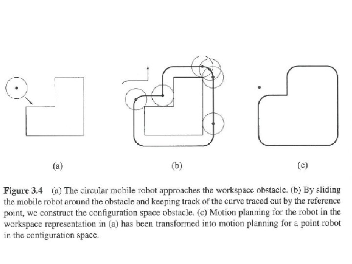
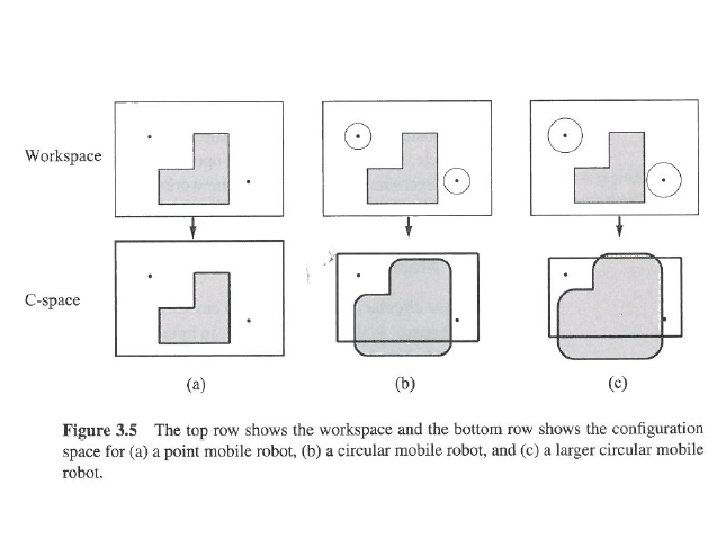
• Configuration: complete specification of the position of every point of the system. Position and orientation. Also, called a pose • Configuration space: space of all possible configurations • Workspace: the 2 D or 3 D ambient space the robot is in.

• Beyond trial and error…. • Establish mathematically how robot should move • Kinematics: how robot will move given motor inputs • Inverse-kinematics: how to move motors to get robot to do what we want https: //www. youtube. com/watch? v=Fz. CORl 5 BU 0 Q
 x. I, y. I, θI Wants to get to")
Robot is at (initial frame) x. I, y. I, θI Wants to get to some location but can’t control x. I, y. I, θI directly

Robot can know • Speeds of wheels: φ1…φn • Steering angle of steerable wheels: β 1…βm • Speed with which steering angles are changing: β 1…βm

Robot can know • Speeds of wheels: φ1…φn • Steering angle of steerable wheels: β 1…βm • Speed with which steering angles are changing: β 1…βm • These define the forward motion of the robot, the forward kinematics: f(φ1…φn, β 1…βm)=[x. I, y. I, θI]T
![Want we want Inverse Kinematics [φ1…φn, β 1…βm] T=f(x. I, y. I, θI)](http://slidetodoc.com/presentation_image_h2/8021270ece867840d3232efe032c17c6/image-19.jpg "Want we want Inverse Kinematics [φ1…φn, β 1…βm] T=f(x. I, y. I, θI)")
Want we want Inverse Kinematics [φ1…φn, β 1…βm] T=f(x. I, y. I, θI)
 • Not")
Robot • Robot knows how movement relative to center of rotation (P) • Not same as knowing how moves in world • Initial Frame • Robot Frame
![• Robot Position: ξI=[x. I, y. I, θI]T • Mapping motion between frames](http://slidetodoc.com/presentation_image_h2/8021270ece867840d3232efe032c17c6/image-21.jpg "• Robot Position: ξI=[x. I, y. I, θI]T • Mapping motion between frames")
• Robot Position: ξI=[x. I, y. I, θI]T • Mapping motion between frames ξR= ? ? ξI
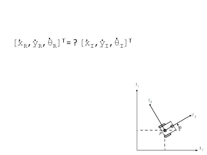
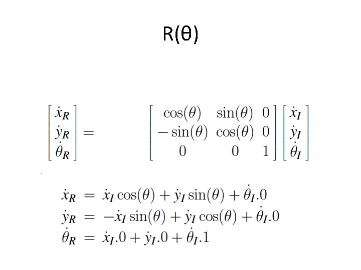
![• Robot Position: ξI=[x. I, y. I, θI]T • Mapping between frames ξR=R(θ)ξI](http://slidetodoc.com/presentation_image_h2/8021270ece867840d3232efe032c17c6/image-23.jpg "• Robot Position: ξI=[x. I, y. I, θI]T • Mapping between frames ξR=R(θ)ξI")
• Robot Position: ξI=[x. I, y. I, θI]T • Mapping between frames ξR=R(θ)ξI =R(θ)[x. I, y. I, θI]T where R(θ)=
ξI • Still isn’t what we want… we want the reverse of")
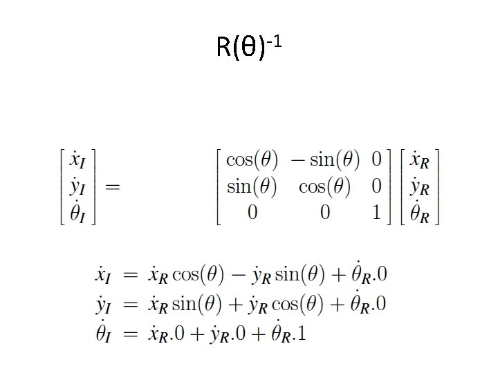
• ξR=R(θ)ξI • Still isn’t what we want… we want the reverse of this • ξI=R(θ)-1ξR

• If we know the relative changes in x, y, and θ, we can find the global position. How do we know what these values are?

• Speed of the wheels • Constraints – Movement on a horizontal plane – Point contact of wheels – Wheels are not deformable – Pure rolling: velocity is 0 at contact point – No friction for rotation – Steering axes orthogonal to surface – Wheels connected by rigid frame

Differential Drive • Wheels rotate at φ • Each wheel contributes rφ/2 to motion of center of rotation • Speed = sum of two wheels • Rotation due to right wheel is ωr=rφ/2 l Counterclockwise about left wheel • l is distance between wheel and center of rotation

Differential Drive • Rotation due to left wheel: ωl=-rφ/2 l Counterclockwise about right wheel • Combining components:

Example 1/3 • • θ=π/2=90 degrees r=1 l=1 φl=4, φr=2 What is the change in the initial frame of reference? sin(π/2)=1, cos(π/2)=0
=1/√ 2,")
Example 2/3 • • θ=π/4=45 degrees rl=2, rr=3 l=5 φl= φr =6 sin(π/4)=1/√ 2, cos(π/4)=1/√ 2
- Slides: 32