
Ga Toroid Vector Magnet Mikko Karppinen Some observations
Ga. Toroid & Vector Magnet Mikko Karppinen
Some observations on Ga. Toroid Defocussing in the H-plane and requires down-stream focussing element(s) • FWD toroid focussing in H-plane • Field uniformity requirements and manufacturing tolerances? • 6 Beam lines combined with +/- 30 deg rotation would cover all angles • 2
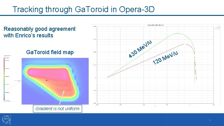
Tracking through Ga. Toroid in Opera-3 D Reasonably good agreement with Enrico’s results u Ga. Toroid field map 0 43 V/ e M 120 V/u e M Gradient is not uniform 3
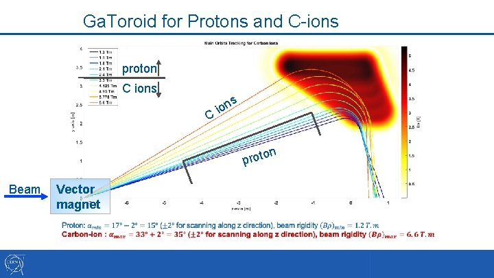
Ga. Toroid for Protons and C-ions proton C ions C s ion o prot Beam Vector magnet n
Straight Vector Magnet • Normal conducting magnet • • 6 -17 tons for Lmag = 2. 5 m Requires very precice actuation through 360° in some 60 s Superferric magnet could be an option Superconducting cos-theta magnet: • • 5 T field for Lmag = 0. 75 m (Nb 3 Sn) Straight magnet excluded (excessive aperture) Tilted (16. 5°) ø 630 mm aperture magnet would still have a mass of 26 tons (*! Actuation even more challenging than iron-dominated magnet *) For Bmean of 2 T in the iron
Curved Combined Function Vector Magnet The concept proposed for SIGNUS could meet the requirements for Vector magnet • Bending angle of 33° +/-2° would still require large aperture • • • 31° (2. 82 T) R 2. 350 m 33° (3. 00 T) R 2. 207 m 35° (3. 18 T) R 2. 081 m => d. R = 269 mm, so with 2/3 GFR the Aperture around ø 403 mm with B nom = 3 T (m ~12 tons) d. R = 162 mm and Ap ~ ø 243 mm with Bnom = 5 T (m ~6 tons) Smaller kick angle range would reduce the aperture and mass Achromat by combining focussing and defocussing CF magnets of 16. 5° • Larger bending angle would reduce the overall length of the gantry • Vector magnet distance from treatment area could allow He bath cooling? • • Both gantry options could benefit from the MBCFD 1 demonstrator development 6
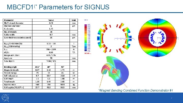
MBCFD 1(* Parameters for SIGNUS *)Magnet Bending Combined Function Demonstrator #1 7
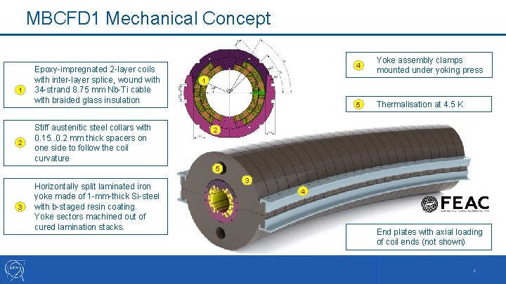
MBCFD 1 Mechanical Concept 1 2 Epoxy-impregnated 2 -layer coils with inter-layer splice, wound with 34 -strand 8. 75 mm Nb-Ti cable with braided glass insulation Stiff austenitic steel collars with 0. 15. . 0. 2 mm thick spacers on one side to follow the coil curvature 4 Yoke assembly clamps mounted under yoking press 5 Thermalisation at 4. 5 K 1 2 5 3 Horizontally split laminated iron yoke made of 1 -mm-thick Si-steel with b-staged resin coating. Yoke sectors machined out of cured lamination stacks. 3 4 End plates with axial loading of coil ends (not shown) 8
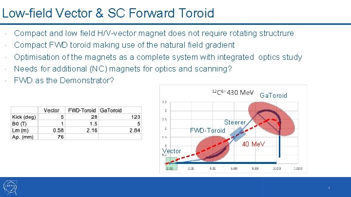
Low-field Vector & SC Forward Toroid • • • Compact and low field H/V-vector magnet does not require rotating structrure Compact FWD toroid making use of the natural field gradient Optimisation of the magnets as a complete system with integrated optics study Needs for additional (NC) magnets for optics and scanning? FWD as the Demonstrator? Ga. Toroid Steerer FWD-Toroid Vector 40 Me. V 9
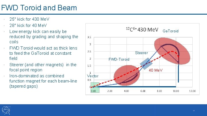
FWD Toroid and Beam • • • 25° kick for 430 Me. V 28° kick for 40 Me. V Low energy kick can easily be reduced by grading and shaping the coils FWD Toroid would act as thick lens to feed the Ga. Toroid at constant field Steerer (and other magnets) in the focal point region Iron-dominated as combined function magnet for each beam-line (tapered gaps) Ga. Toroid Steerer FWD-Toroid 40 Me. V Vector 10
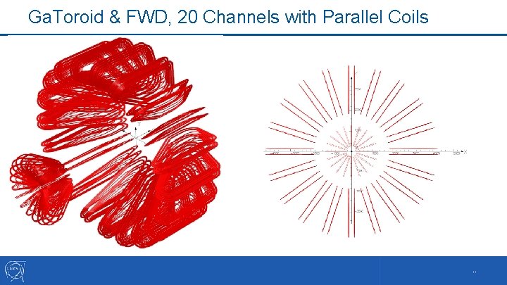
Ga. Toroid & FWD, 20 Channels with Parallel Coils 11
Summary Vector magnet requires precise rotating structure • Normal conducting / superferric vector magnet would have a mass of over 6 tons • Curved superconducting combined function vector magnet: • • • FWD toroid with low-field vector magnet: • • • Reduced king angle range from +/- 2° would reduce the aperture and mass Provides more flexibility for beam optics (F/DF with cold quadrupole, . . ) Increased bending angle would reduce the overall length of the gantry system FWD could be built as a demonstrator and even possibly tested with beam Compact H/V-vector magnet would not require rotation Pushing the complexity of the gantry system Beam dynamics already challenging for the Ga. Toroid Limited gantry rotation would allow reduction of beam channels while covering all treatment angles Gantry requires integrated design study including all magnetic elements 12

- Slides: 13