
Future upgrade of the neutrino beamline for multiMW
Future upgrade of the neutrino beam-line for multi-MW beam 5 th Hyper-Kamiokande open meeting @ Vancouver July-20 -2014 Yuichi Oyama (KEK) (for T 2 K neutrino beam-line group)
Introduction l When the J-PARC project started, the primary goal of the beam power in the neutrino beam line was 750 k. W. Upgrade to 4 MW was second step in the future. l ~750 k. W beam from the accelerators will be within our reach by ~2017 if the budget is funded timely. It is possible to accept this beam power, with significant improvement for steady operation. l For operation beyond 750 k. W, critical improvements are needed. l In this talk, future upgrade required for ~2 MW beam power is reported.
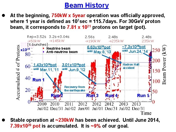
Beam History l At the beginning, 750 k. W x 5 year operation was officially approved, where 1 year is defined as 107 sec = 115. 7 days. For 30 Ge. V proton beam, it corresponds to 7. 81 x 1021 protons on target (pot). Rep=3. 52 s 3. 04 s 145 k. W 50 k. W [6 bunches] Neutrino beam x 1019 Anti-neutrino beam 2. 56 s 190 k. W 2. 48 s 235 k. W 6. 63 x 1020 pot until May. 8, ’ 13 ~7. 3 x 10²⁰ pot until Jun. 24, ’ 14 Hadron Hall accident 1. 43 x 1020 pot 3. 01 x 1020 pot until Mar. 11, ’ 11 until Jun. 9, ’ 12 Run 1 Recovery from the earthquake Run 2 l Run 3 Run 4 Run 5 Stable operation at ~230 k. W has been achieved. Until June 2014, 7. 39 x 1020 pot is accumulated. It is ~9% of our goal.
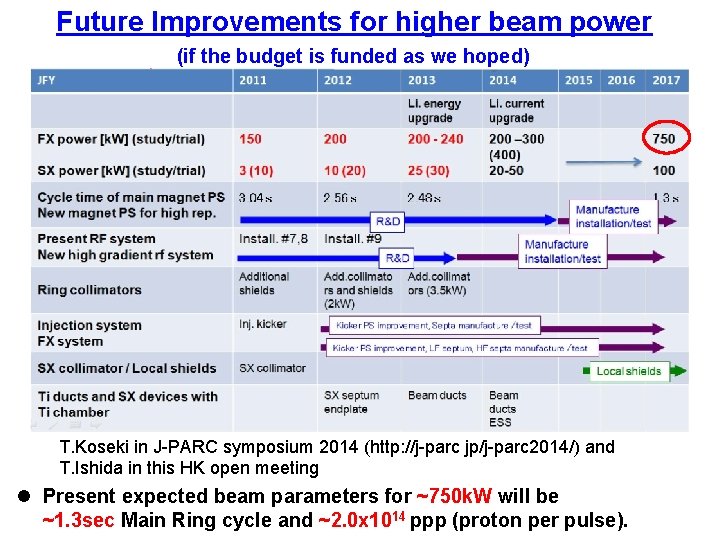
Future Improvements for higher beam power (if the budget is funded as we hoped) T. Koseki in J-PARC symposium 2014 (http: //j-parc jp/j-parc 2014/) and T. Ishida in this HK open meeting l Present expected beam parameters for ~750 k. W will be ~1. 3 sec Main Ring cycle and ~2. 0 x 1014 ppp (proton per pulse).
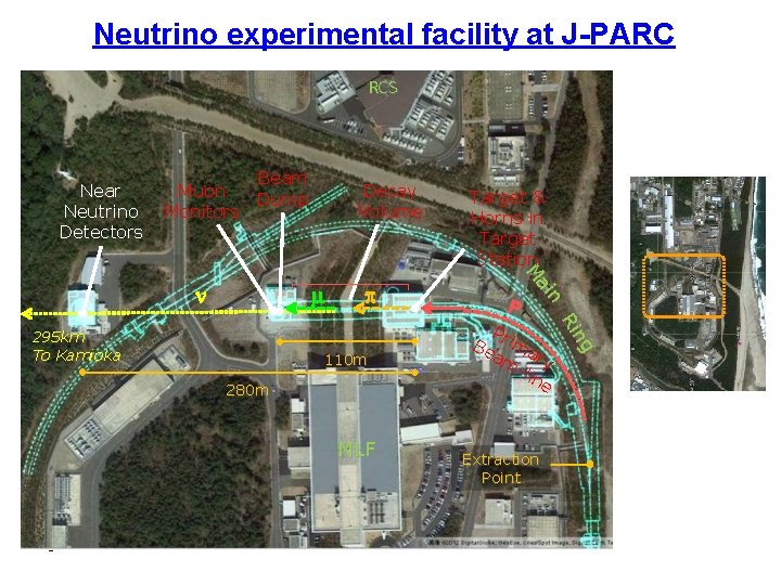
Neutrino experimental facility at J-PARC RCS Near Neutrino Detectors Muon Monitors Beam Dump m 110 m 280 m MLF 5 P P Be rima am ry -li ne Extraction Point ng Ri 295 km To Kamioka p Target & Horns in Target Station n ai M n Decay Volume
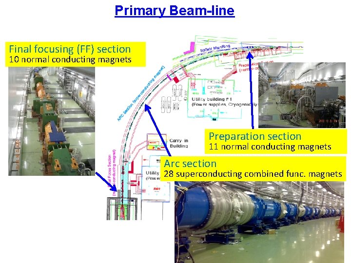
Primary Beam-line Final focusing (FF) section 10 normal conducting magnets Preparation section 11 normal conducting magnets Arc section 28 superconducting combined func. magnets
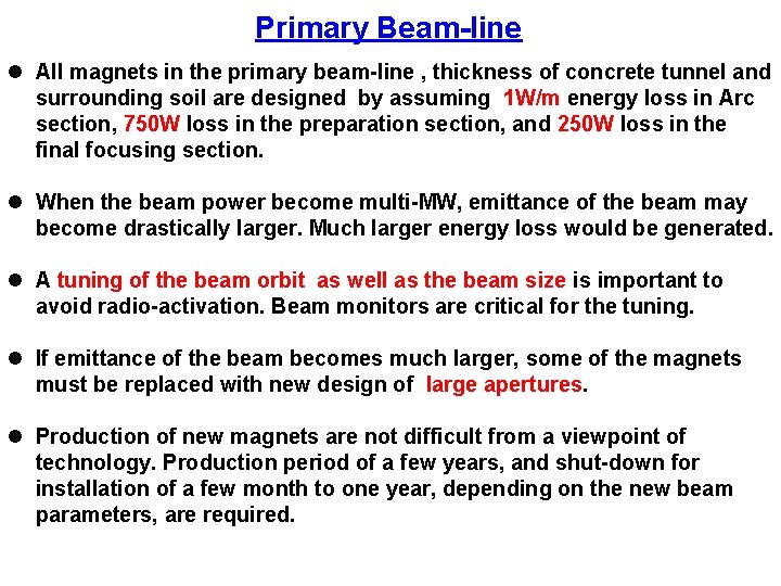
Primary Beam-line l All magnets in the primary beam-line , thickness of concrete tunnel and surrounding soil are designed by assuming 1 W/m energy loss in Arc section, 750 W loss in the preparation section, and 250 W loss in the final focusing section. l When the beam power become multi-MW, emittance of the beam may become drastically larger. Much larger energy loss would be generated. l A tuning of the beam orbit as well as the beam size is important to avoid radio-activation. Beam monitors are critical for the tuning. l If emittance of the beam becomes much larger, some of the magnets must be replaced with new design of large apertures. l Production of new magnets are not difficult from a viewpoint of technology. Production period of a few years, and shut-down for installation of a few month to one year, depending on the new beam parameters, are required.
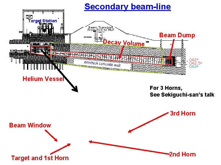
Secondary beam-line Target Station Beam Transport From RCS to MLF Decay Volume 6 m-thick con crete wall Beam Dump OA 2 o OA 2. 5 o OA 3 o Helium Vessel For 3 Horns, See Sekiguchi-san’s talk 3 rd Horn Beam Window Target and 1 st Horn 2 nd Horn
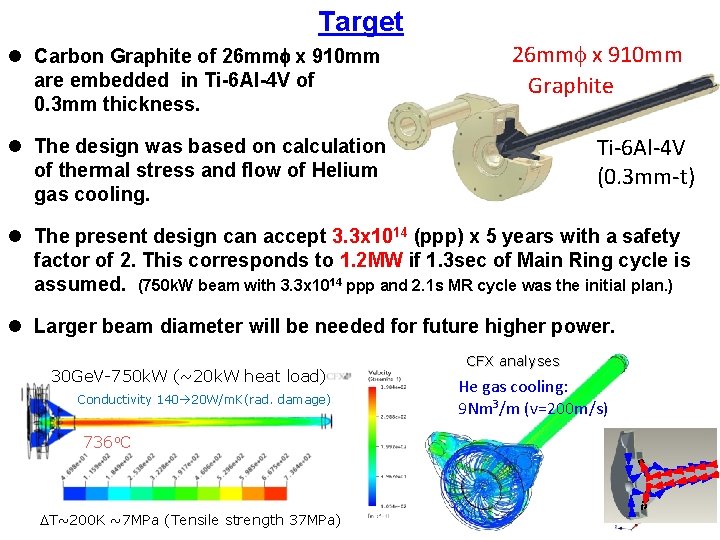
Target l Carbon Graphite of 26 mmf x 910 mm are embedded in Ti-6 Al-4 V of 0. 3 mm thickness. 26 mmf x 910 mm Graphite Ti-6 Al-4 V (0. 3 mm-t) l The design was based on calculation of thermal stress and flow of Helium gas cooling. l The present design can accept 3. 3 x 10¹⁴ (ppp) x 5 years with a safety factor of 2. This corresponds to 1. 2 MW if 1. 3 sec of Main Ring cycle is assumed. (750 k. W beam with 3. 3 x 10¹⁴ ppp and 2. 1 s MR cycle was the initial plan. ) l Larger beam diameter will be needed for future higher power. 30 Ge. V-750 k. W (~20 k. W heat load) Conductivity 140 20 W/m. K(rad. damage) 736 o. C DT~200 K ~7 MPa (Tensile strength 37 MPa) CFX analyses He gas cooling: 9 Nm 3/m (v=200 m/s)
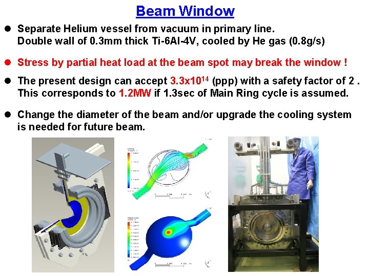
Beam Window l Separate Helium vessel from vacuum in primary line. Double wall of 0. 3 mm thick Ti-6 Al-4 V, cooled by He gas (0. 8 g/s) l Stress by partial heat load at the beam spot may break the window ! l The present design can accept 3. 3 x 10¹⁴ (ppp) with a safety factor of 2. This corresponds to 1. 2 MW if 1. 3 sec of Main Ring cycle is assumed. l Change the diameter of the beam and/or upgrade the cooling system is needed for future beam.
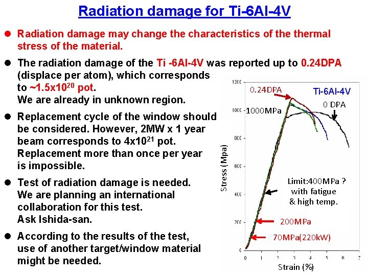
Radiation damage for Ti-6 Al-4 V l Radiation damage may change the characteristics of thermal stress of the material. l The radiation damage of the Ti -6 Al-4 V was reported up to 0. 24 DPA (displace per atom), which corresponds to ~1. 5 x 10²⁰ pot. 0. 24 DPA Ti-6 Al-4 V We are already in unknown region. 0 DPA l Test of radiation damage is needed. We are planning an international collaboration for this test. Ask Ishida-san. l According to the results of the test, use of another target/window material might be needed. 1000 MPa Stress (Mpa) l Replacement cycle of the window should be considered. However, 2 MW x 1 year beam corresponds to 4 x 10²¹ pot. Replacement more than once per year is impossible. Limit: 400 MPa ? with fatigue & high temp. 200 MPa 70 MPa(220 k. W) Strain (%)
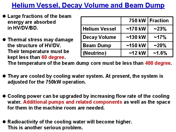
Helium Vessel, Decay Volume and Beam Dump l Large fractions of the beam energy are absorbed in HV/DV/BD. 750 k. W Fraction Helium Vessel ~170 k. W ~23% Decay Volume ~130 k. W ~17% l Thermal stress may damage Beam Dump ~150 k. W ~20% the structure of HV/DV. Their temperature must be (Neutrino) ~12 k. W ~1. 6% kept less than 60 degree. The temperature of the beam dump core must be less than 400 degree. l They are cooled by cooling water system. At present, the system is adjusted for the 750 k. W operation. l Cooling power can be upgraded by increasing flow rate of the cooling water. Additional pumps and related components as well as the space for them in the machine room are needed. l Radioactivity of the cooling water will become higher. This is another serious problem.
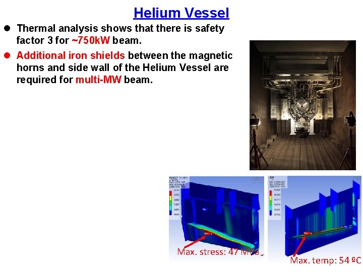
Helium Vessel l Thermal analysis shows that there is safety factor 3 for ~750 k. W beam. l Additional iron shields between the magnetic horns and side wall of the Helium Vessel are required for multi-MW beam. Max. stress: 47 MPa Max. temp: 54 ºC
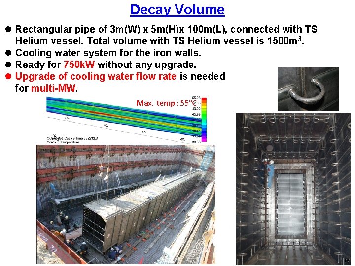
Decay Volume l Rectangular pipe of 3 m(W) x 5 m(H)x 100 m(L), connected with TS Helium vessel. Total volume with TS Helium vessel is 1500 m 3. l Cooling water system for the iron walls. l Ready for 750 k. W without any upgrade. l Upgrade of cooling water flow rate is needed for multi-MW. Max. temp: 55 C 14
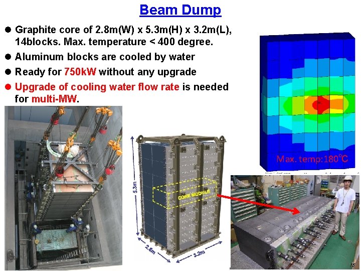
Beam Dump l Graphite core of 2. 8 m(W) x 5. 3 m(H) x 3. 2 m(L), 14 blocks. Max. temperature < 400 degree. l Aluminum blocks are cooled by water l Ready for 750 k. W without any upgrade l Upgrade of cooling water flow rate is needed for multi-MW. Max. temp: 180℃ 15
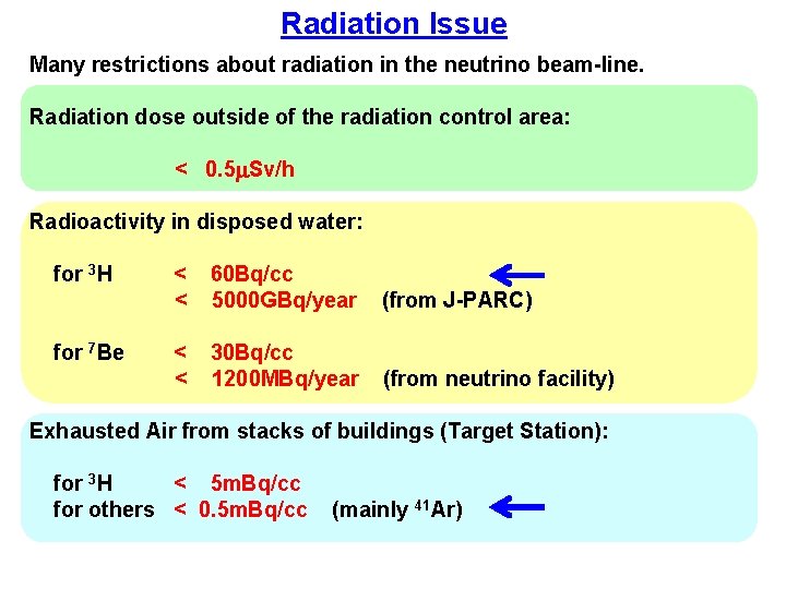
Radiation Issue Many restrictions about radiation in the neutrino beam-line. Radiation dose outside of the radiation control area: < 0. 5 m. Sv/h Radioactivity in disposed water: for 3 H for 7 Be < < 60 Bq/cc 5000 GBq/year (from J-PARC) < < 30 Bq/cc 1200 MBq/year (from neutrino facility) Exhausted Air from stacks of buildings (Target Station): for 3 H < 5 m. Bq/cc for others < 0. 5 m. Bq/cc (mainly 41 Ar)
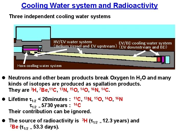
Cooling Water system and Radioactivity Three independent cooling water systems HV/DV water system DV/BD cooling water system (Helium Vessel and DV upstream) (DV downstream and BD) Horn cooling water system l Neutrons and other beam products break Oxygen In H 2 O and many kinds of isotopes are produced as spallation products. They are 3 H, 7 Be, 11 C, 13 N, 15 O, 14 O, 16 N, 14 C. l Lifetime t 1/2 < 20 minutes : 11 C, 13 N, 15 O, 14 O, 16 N t 1/2 = 5730 years : 14 C Their contribution can be ignored. l The source of radioactivity is 3 H (t 1/2 = 12. 3 years) and 7 Be (t 1/2 = 53. 3 days).
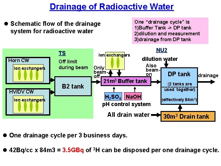
Drainage of Radioactive Water One “drainage cycle” is 1)Buffer Tank -> DP tank 2)dilution and measurement 3)drainage from DP tank l Schematic flow of the drainage system for radioactive water TS Horn CW Ion exchangers HV/DV CW Ion exchangers Off limit during beam B 2 tank Ion exchangers Only beamoff NU 2 dilution water Also beamon 21 m 3 Buffer tank DP tank drainage (2 tanks are used together) H 2 SO 4 Na. OH p. H control system All drain water (effectively 84 m 3) 30 m 3 Drain tank l One drainage cycle per 3 business days. l 42 Bq/cc x 84 m 3 = 3. 5 GBq of 3 H can be disposed per one drainage cycle.
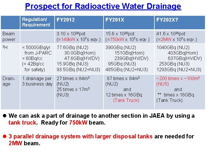
Prospect for Radioactive Water Drainage Regulation/ Requirement Beam power FY 2012 FY 201 X FY 202 X? 3. 10 x 1020 pot (=149 k. W x 107 s eqv. ) 15. 6 x 10²⁰ pot (=750 k. W x 107 s eqv. ) 41. 6 x 10²⁰ pot (=2 MW x 107 s eqv. ) 77. 6 GBq (NU 2) 30. 0 GBq(Horn) 47. 6 GBq(HV/DV) 15. 9 GBq (NU 3) 93. 5 GBq (NU 2+NU 3) 390 GBq (NU 2) 151 GBq(Horn) 239 GBq(HV/DV) 95 GBq (NU 3) 485 GBq (NU 2+NU 3) 1040 GBq (NU 2) 403 GBq(Horn) 637 GBq(HV/DV) 253 GBq (NU 3) 1293 GBq (NU 2+NU 3) 87 times x 84 m 3 (NU 2) and 12 times x 16 GBq (Tank Truck) ~200 times x ~100 m 3 (NU 5) and ** times x 16 GBq (Tank Truck) 3 H < 5000 GBq/yr from J-PARC < 60 Bq/cc (< 42 Bq/cc for safety) Drainage 1 drainage per 27 times x 84 m 3 3 business day (NU 2) 25 times x 17 m 3 (NU 3) l We can ask a part of drainage to another section in JAEA by using a tank truck. Ready for 750 k. W beam. l 3 parallel drainage system with larger disposal tanks are needed for 2 MW beam.
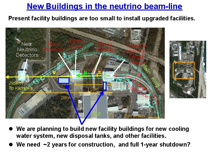
New Buildings in the neutrino beam-line Present facility buildings are too RCS small to install upgraded facilities. Near Neutrino Detectors Muon Monitors Beam Dump m 110 m 280 m MLF P P Be rima am ry -li ne ng Ri 295 km To Kamioka p Target & Horns in Target Station n ai M n Decay Volume Extraction Point l We are planning to build new facility buildings for new cooling water system, new disposal tanks, and other facilities. 20 l We need ~2 years for construction, and full 1 -year shutdown?
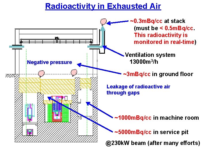
Radioactivity in Exhausted Air ~0. 3 m. Bq/cc at stack (must be < 0. 5 m. Bq/cc. This radioactivity is monitored in real-time) Negative pressure Ventilation system 13000 m 3/h ~3 m. Bq/cc in ground floor Leakage of radioactive air through gaps ~1000 m. Bq/cc in machine room ~5000 m. Bq/cc in service pit @230 k. W beam (after many efforts)
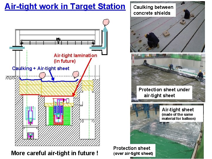
Air-tight work in Target Station Caulking between concrete shields Air-tight lamination (in future) Caulking + Air-tight sheet Protection sheet under air-tight sheet Air-tight sheet (made of the same material for balloon) More careful air-tight in future ! Protection sheet (over air-tight sheet)
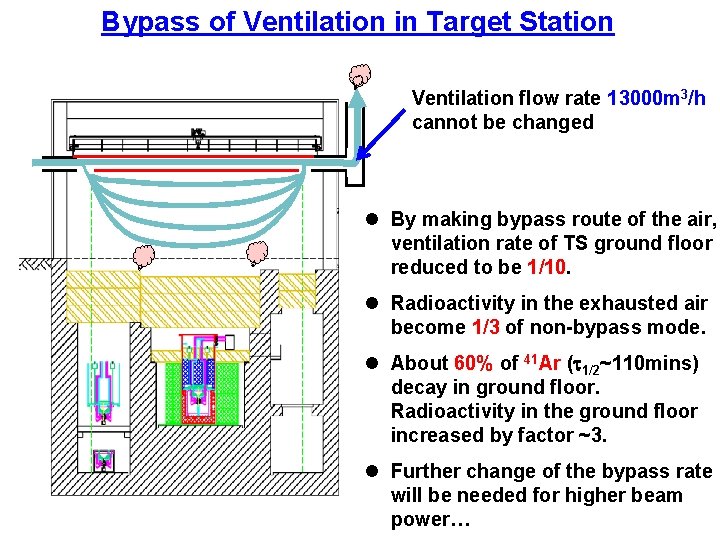
Bypass of Ventilation in Target Station Ventilation flow rate 13000 m 3/h cannot be changed l By making bypass route of the air, ventilation rate of TS ground floor reduced to be 1/10. l Radioactivity in the exhausted air become 1/3 of non-bypass mode. l About 60% of 41 Ar (t 1/2~110 mins) decay in ground floor. Radioactivity in the ground floor increased by factor ~3. l Further change of the bypass rate will be needed for higher beam power…
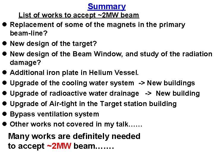
Summary l l l l l List of works to accept ~2 MW beam Replacement of some of the magnets in the primary beam-line? New design of the target? New design of the Beam Window, and study of the radiation damage? Additional iron plate in Helium Vessel. Upgrade of the cooling water system -> New buildings Upgrade of radioactive water drainage -> New building Upgrade of Air-tight in the Target station building Bypass ventilation system Other works not covered in my talk…… Many works are definitely needed to accept ~2 MW beam…….

END
- Slides: 25