
Future interests in high gradients at FERMIElettra FEL
- Slides: 10
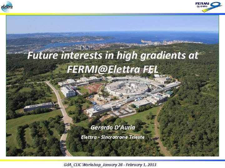
Future interests in high gradients at FERMI@Elettra FEL Gerardo D’Auria Elettra - Sincrotrone Trieste Gd. A_CLIC Workshop_January 28 - February 1, 2013
Outline Ø The FERMI@Elettra FEL project Ø Present machine layout Ø Weaknesses and possible upgradings Ø C/X band test station Ø Outlook and conclusions Gd. A_CLIC Workshop_January 28 - February 1, 2013 2
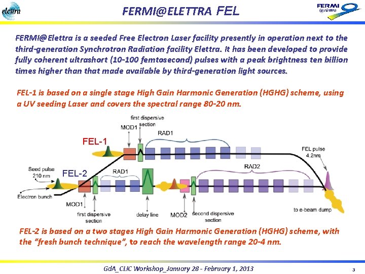
FERMI@ELETTRA FEL FERMI@Elettra is a seeded Free Electron Laser facility presently in operation next to the third-generation Synchrotron Radiation facility Elettra. It has been developed to provide fully coherent ultrashort (10 -100 femtosecond) pulses with a peak brightness ten billion times higher than that made available by third-generation light sources. FEL-1 is based on a single stage High Gain Harmonic Generation (HGHG) scheme, using a UV seeding Laser and covers the spectral range 80 -20 nm. FEL-1 FEL-2 is based on a two stages High Gain Harmonic Generation (HGHG) scheme, with the “fresh bunch technique”, to reach the wavelength range 20 -4 nm. Gd. A_CLIC Workshop_January 28 - February 1, 2013 3
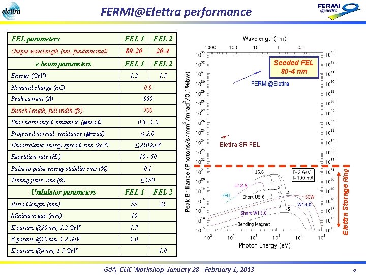
FERMI@Elettra performance FEL parameters FEL 1 FEL 2 Output wavelength (nm, fundamental) 80 -20 20 -4 FEL 1 FEL 2 1. 5 e-beam parameters Energy (Ge. V) Nominal charge (n. C) 0. 8 Peak current (A) 850 Bunch length, full width (fs) 700 Slice normalized emittance (mmrad) 0. 8 - 1. 2 Projected normal. emittance (mmrad) ≤ 2. 0 Uncorrelated energy spread, rms (ke. V) ≤ 250 ke. V 10 - 50 Pulse to pulse energy stability rms (%) 0. 1 Timing jitter, rms (fs) Undulator parameters ≤ 150 FEL 1 FEL 2 Period length (mm) 55 35 Minimum gap (mm) 10 K param. @20 nm, 1. 2 Ge. V 1. 7 K param. @10 nm, 1. 2 Ge. V 1. 0 K param. @4 nm, 1. 5 Ge. V Elettra SR FEL Elettra Storage Ring Repetition rate (Hz) Seeded FEL 80 -4 nm 1. 0 Gd. A_CLIC Workshop_January 28 - February 1, 2013 4
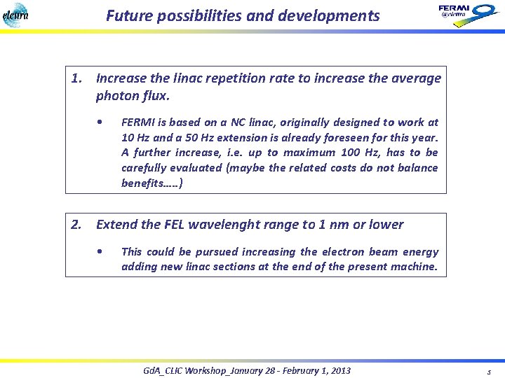
Future possibilities and developments 1. Increase the linac repetition rate to increase the average photon flux. • FERMI is based on a NC linac, originally designed to work at 10 Hz and a 50 Hz extension is already foreseen for this year. A further increase, i. e. up to maximum 100 Hz, has to be carefully evaluated (maybe the related costs do not balance benefits…. . ) 2. Extend the FEL wavelenght range to 1 nm or lower • This could be pursued increasing the electron beam energy adding new linac sections at the end of the present machine. Gd. A_CLIC Workshop_January 28 - February 1, 2013 5
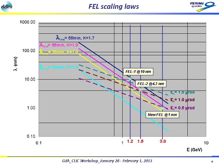
FEL scaling laws l. Und= 55 mm, K=1. 7 l. Und= 55 mm, K=1. 0 l. Und= 35 mm, K=1. 0 l. Und= 10 mm, K=1. 0 FEL-1 @10 nm * FEL-2 @4. 2 nm * * εn= 1. 5 mrad εn= 1. 0 mrad εn= 0. 5 mrad New FEL @1 nm 1. 2 1. 5 Gd. A_CLIC Workshop_January 28 - February 1, 2013 3. 0 6
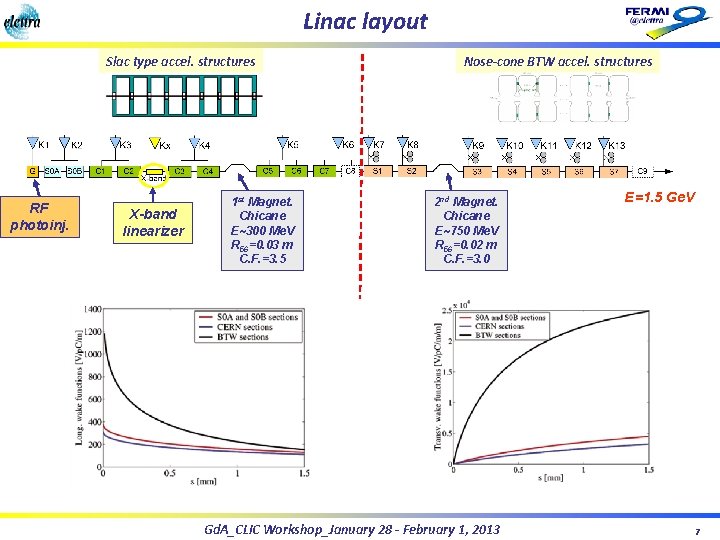
Linac layout Slac type accel. structures RF photoinj. X-band linearizer 1 st Magnet. Chicane E~300 Me. V R 56=0. 03 m C. F. =3. 5 Nose-cone BTW accel. structures 2 nd Magnet. Chicane E~750 Me. V R 56=0. 02 m C. F. =3. 0 Gd. A_CLIC Workshop_January 28 - February 1, 2013 E=1. 5 Ge. V 7
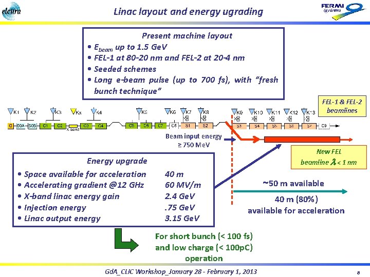
Linac layout and energy ugrading Present machine layout • Ebeam up to 1. 5 Ge. V • FEL-1 at 80 -20 nm and FEL-2 at 20 -4 nm • Seeded schemes • Long e-beam pulse (up to 700 fs), with “fresh bunch technique” FEL-1 & FEL-2 beamlines Beam input energy ≥ 750 Me. V Energy upgrade • Space available for acceleration • Accelerating gradient @12 GHz • X-band linac energy gain • Injection energy • Linac output energy New FEL beamline l < 1 nm 40 m 60 MV/m 2. 4 Ge. V. 75 Ge. V 3. 15 Ge. V ~50 m available 40 m (80%) available for acceleration For short bunch (< 100 fs) and low charge (< 100 p. C) operation Gd. A_CLIC Workshop_January 28 - February 1, 2013 8
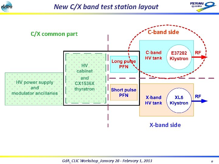
New C/X band test station layout C/X common part C-band side X-band side Gd. A_CLIC Workshop_January 28 - February 1, 2013 9
Outlook and conclusions Ø An important upgrading of the FERMI@Elettra FEL could be the extension of its waveleght range down to 1 nm or lower. Ø This would require an increase of the electron beam energy up to 3. 0 Ge. V. Ø Due to the limited space available in the machine tunnel, the use of very high gradient structures is required. Ø The X-band technology, working at 60 MV/m, meets this requirement. Ø To explore more accurately this possibility, the assembly of a C/X band testing station is now being considered. Gd. A_CLIC Workshop_January 28 - February 1, 2013