
Future Circular Collider Frank Zimmermann for the FCC

- Slides: 57
Future Circular Collider Frank Zimmermann for the FCC collaboration Future Research Infrastructures – Challenges and Opportunities Varenna, 9 July 2015 gratefully acknowledging input from Michael Benedikt & Johannes Gutleber Work supported by the European Commission under Capacities 7 th Framework Programme projest Eu. CARD-2, Grant Agreement 312453, and the HORIZON 2020 project Euro. Cir. Col, Grant Agreement 654305 Photo: courtesy J. Wenninger
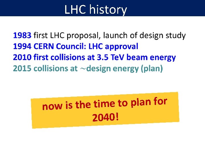
LHC history r o f n la p o t e im t e h now is t 2040!
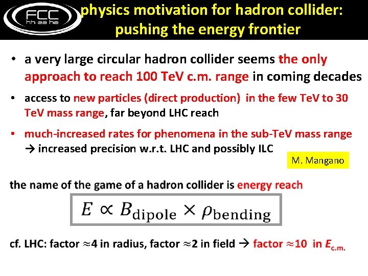
physics motivation for hadron collider: pushing the energy frontier • a very large circular hadron collider seems the only approach to reach 100 Te. V c. m. range in coming decades • access to new particles (direct production) in the few Te. V to 30 Te. V mass range, far beyond LHC reach • much-increased rates for phenomena in the sub-Te. V mass range → increased precision w. r. t. LHC and possibly ILC M. Mangano
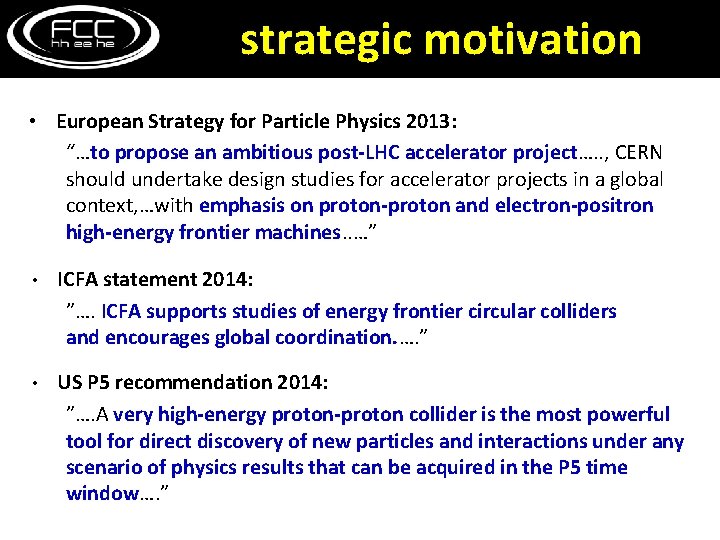
strategic motivation • European Strategy for Particle Physics 2013: “…to propose an ambitious post-LHC accelerator project…. . , CERN should undertake design studies for accelerator projects in a global context, …with emphasis on proton-proton and electron-positron high-energy frontier machines. . …” • ICFA statement 2014: ”…. ICFA supports studies of energy frontier circular colliders and encourages global coordination. …. ” • US P 5 recommendation 2014: ”…. A very high-energy proton-proton collider is the most powerful tool for direct discovery of new particles and interactions under any scenario of physics results that can be acquired in the P 5 time window…. ”
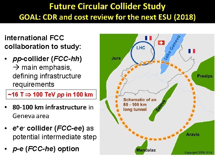
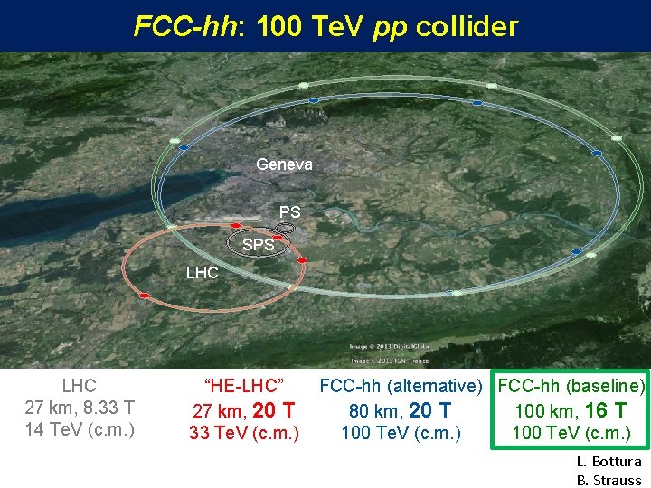
Future Circular Collider Study GOAL: CDR and cost review for the next ESU (2018) international FCC collaboration to study: • pp-collider (FCC-hh) main emphasis, defining infrastructure requirements ~16 T 100 Te. V pp in 100 km • 80 -100 km infrastructure in Geneva area • e+e- collider (FCC-ee) as potential intermediate step • p-e (FCC-he) option
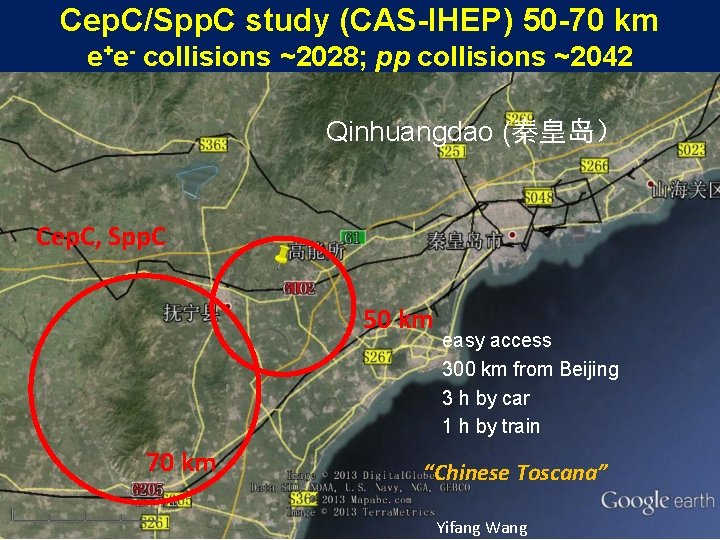
Cep. C/Spp. C study (CAS-IHEP) 50 -70 km e+e- collisions ~2028; pp collisions ~2042 Qinhuangdao (秦皇岛) Cep. C, Spp. C 50 km 70 km easy access 300 km from Beijing 3 h by car 1 h by train “Chinese Toscana” Yifang Wang
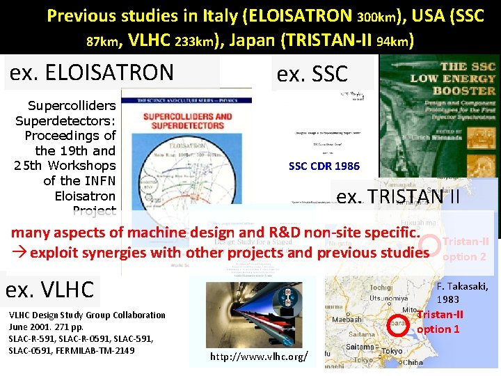
Previous studies in Italy (ELOISATRON 300 km), USA (SSC 87 km, VLHC 233 km), Japan (TRISTAN-II 94 km) ex. ELOISATRON Supercolliders Superdetectors: Proceedings of the 19 th and 25 th Workshops of the INFN Eloisatron Project ex. SSC CDR 1986 ex. TRISTAN II many aspects of machine design and R&D non-site specific. Tristan-II H. Ulrich Wienands, The exploit synergies with other projects and previous studies option 2 SSC Low Energy Booster: Design and Component Prototypes for the First F. Takasaki, Injector Synchrotron, IEEE 1983 Press, 1997 ex. VLHC Design Study Group Collaboration June 2001. 271 pp. SLAC-R-591, SLAC-R-0591, SLAC-591, SLAC-0591, FERMILAB-TM-2149 Tristan-II option 1 http: //www. vlhc. org/
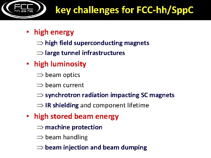
key challenges for FCC-hh/Spp. C • high energy high field superconducting magnets large tunnel infrastructures • high luminosity beam optics beam current synchrotron radiation impacting SC magnets IR shielding and component lifetime • high stored beam energy machine protection beam handling beam injection and beam dumping
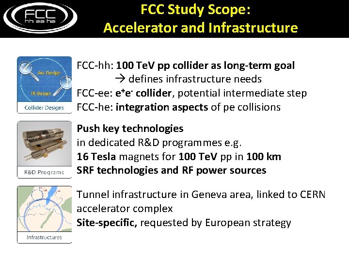
FCC Study Scope: Accelerator and Infrastructure FCC-hh: 100 Te. V pp collider as long-term goal defines infrastructure needs FCC-ee: e+e- collider, potential intermediate step FCC-he: integration aspects of pe collisions Push key technologies in dedicated R&D programmes e. g. 16 Tesla magnets for 100 Te. V pp in 100 km SRF technologies and RF power sources Tunnel infrastructure in Geneva area, linked to CERN accelerator complex Site-specific, requested by European strategy
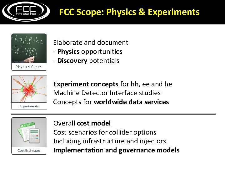
FCC Scope: Physics & Experiments Elaborate and document - Physics opportunities - Discovery potentials Experiment concepts for hh, ee and he Machine Detector Interface studies Concepts for worldwide data services Overall cost model Cost scenarios for collider options Including infrastructure and injectors Implementation and governance models
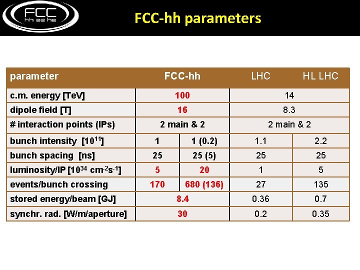
FCC-hh parameters parameter FCC-hh LHC HL LHC c. m. energy [Te. V] 100 14 dipole field [T] 16 8. 3 2 main & 2 # interaction points (IPs) bunch intensity [1011] 1 1 (0. 2) 1. 1 2. 2 bunch spacing [ns] 25 25 (5) 25 luminosity/IP [1034 cm-2 s-1] 5 20 1 5 170 680 (136) 27 135 events/bunch crossing stored energy/beam [GJ] 8. 4 0. 36 0. 7 synchr. rad. [W/m/aperture] 30 0. 2 0. 35
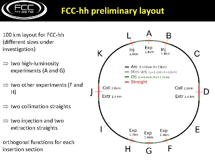
FCC-hh preliminary layout 100 km layout for FCC-hh (different sizes under investigation) two high-luminosity experiments (A and G) two other experiments (F and H) two collimation straights two injection and two extraction straights orthogonal functions for each insertion section
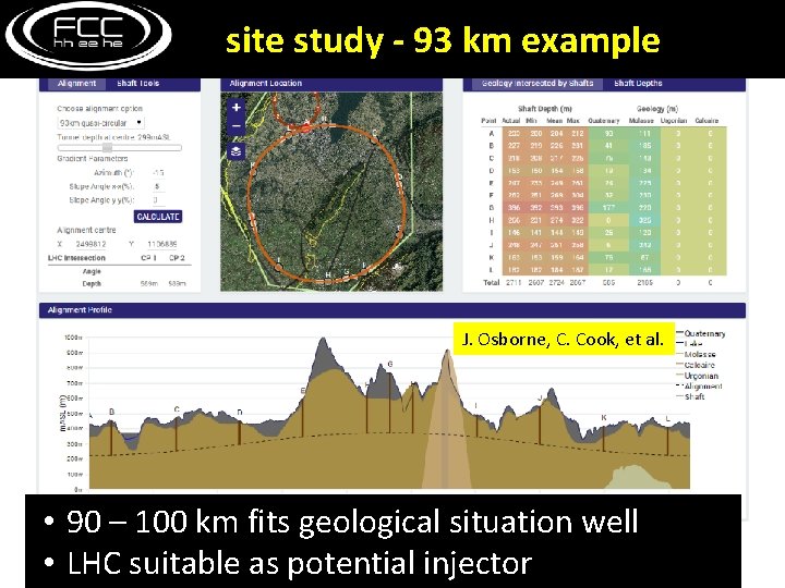
site study - 93 km example J. Osborne, C. Cook, et al. • 90 – 100 km fits geological situation well • LHC suitable as potential injector
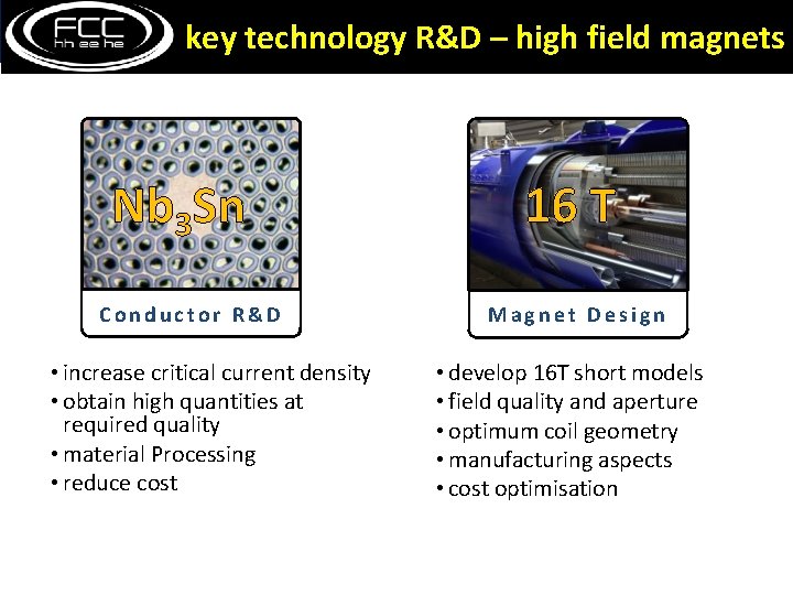
key technology R&D – high field magnets Nb 3 Sn Conductor R&D • increase critical current density • obtain high quantities at required quality • material Processing • reduce cost 16 T Magnet Design • develop 16 T short models • field quality and aperture • optimum coil geometry • manufacturing aspects • cost optimisation
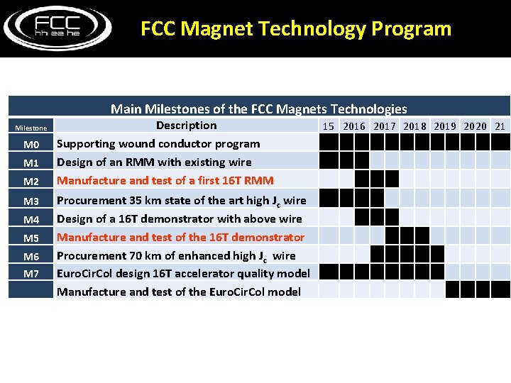
FCC Magnet Technology Program Main Milestones of the FCC Magnets Technologies Milestone M 0 M 1 M 2 M 3 M 4 M 5 M 6 M 7 Description Supporting wound conductor program Design of an RMM with existing wire Manufacture and test of a first 16 T RMM Procurement 35 km state of the art high Jc wire Design of a 16 T demonstrator with above wire Manufacture and test of the 16 T demonstrator Procurement 70 km of enhanced high Jc wire Euro. Cir. Col design 16 T accelerator quality model Manufacture and test of the Euro. Cir. Col model 15 2016 2017 2018 2019 2020 21
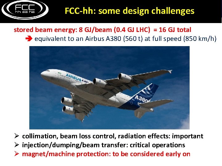
FCC-hh: some design challenges stored beam energy: 8 GJ/beam (0. 4 GJ LHC) = 16 GJ total equivalent to an Airbus A 380 (560 t) at full speed (850 km/h) Ø collimation, beam loss control, radiation effects: important Ø injection/dumping/beam transfer: critical operations Ø magnet/machine protection: to be considered early on
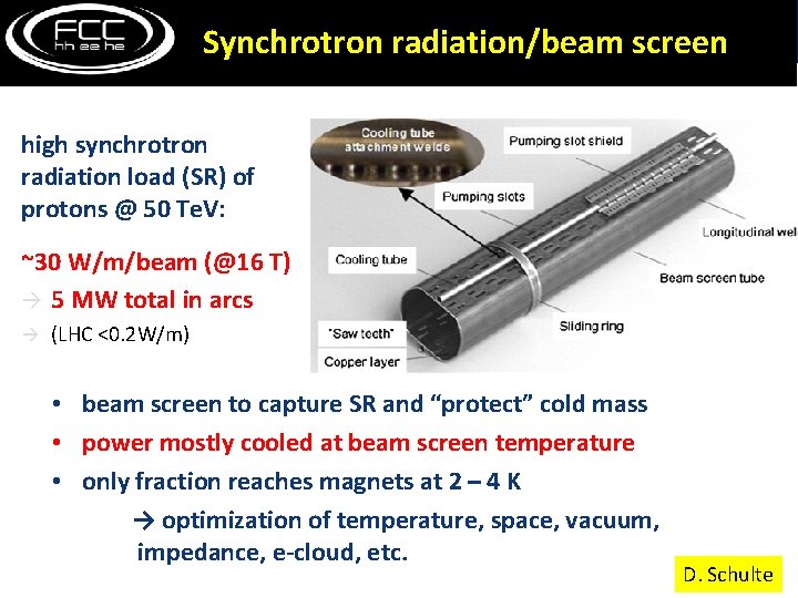
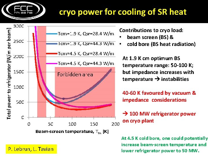
Synchrotron radiation/beam screen high synchrotron radiation load (SR) of protons @ 50 Te. V: ~30 W/m/beam (@16 T) 5 MW total in arcs (LHC <0. 2 W/m) • beam screen to capture SR and “protect” cold mass • power mostly cooled at beam screen temperature • only fraction reaches magnets at 2 – 4 K → optimization of temperature, space, vacuum, impedance, e-cloud, etc. D. Schulte
contributions: beam screen (BS) & cold bore (BS heat radiation) cryo power for cooling of SR heat Contributions to cryo load: • beam screen (BS) & • cold bore (BS heat radiation) At 1. 9 K cm optimum BS temperature range: 50 -100 K; but impedance increases with temperature instabilities 40 -60 K favoured by vacuum & impedance considerations 100 MW refrigerator power on cryo plant P. Lebrun, L. Tavian At 4. 5 K cold bore, one could potentially increase beam-screen temperature and lower refrigerator power to 50 MW.
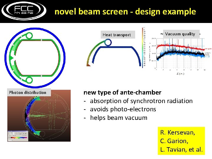
novel beam screen - design example Heat transport Photon distribution Vacuum quality new type of ante-chamber - absorption of synchrotron radiation - avoids photo-electrons - helps beam vacuum R. Kersevan, C. Garion, L. Tavian, et al.
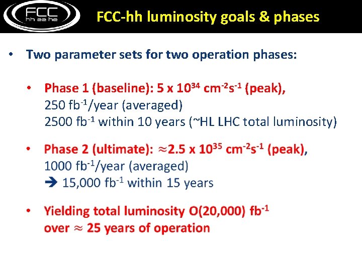
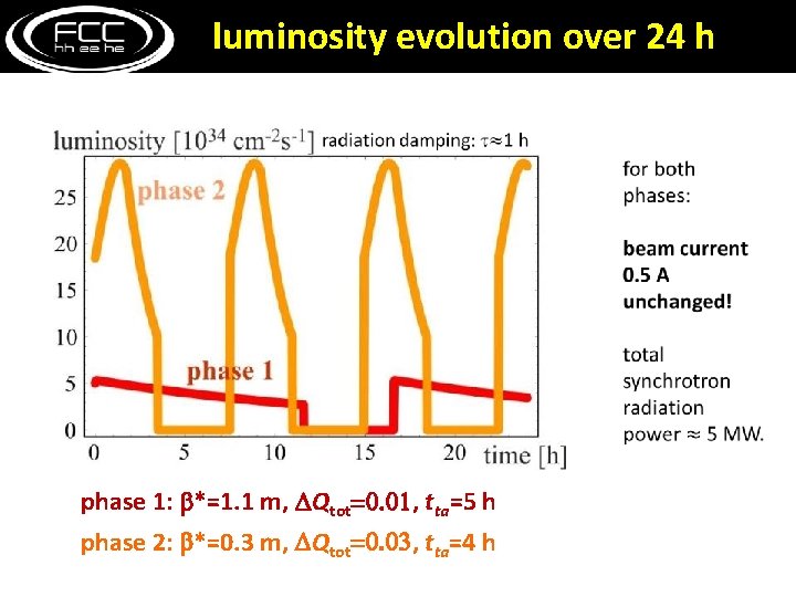
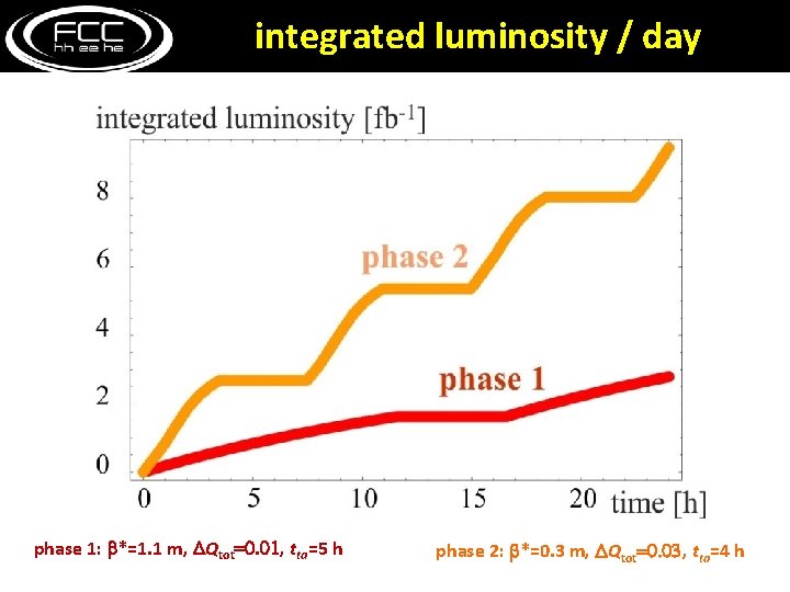
FCC-hh luminosity goals & phases • Two parameter sets for two operation phases: • Phase 1 (baseline): 5 x 1034 cm-2 s-1 (peak), 250 fb-1/year (averaged) 2500 fb-1 within 10 years (~HL LHC total luminosity)
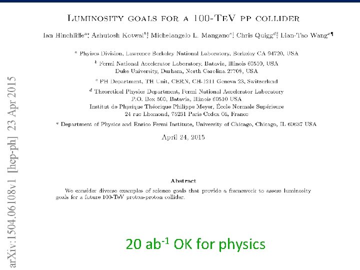
20 ab-1 OK for physics
luminosity evolution over 24 h phase 1: b*=1. 1 m, DQtot=0. 01, tta=5 h phase 2: b*=0. 3 m, DQtot=0. 03, tta=4 h
integrated luminosity / day phase 1: b*=1. 1 m, DQtot=0. 01, tta=5 h phase 2: b*=0. 3 m, DQtot=0. 03, tta=4 h
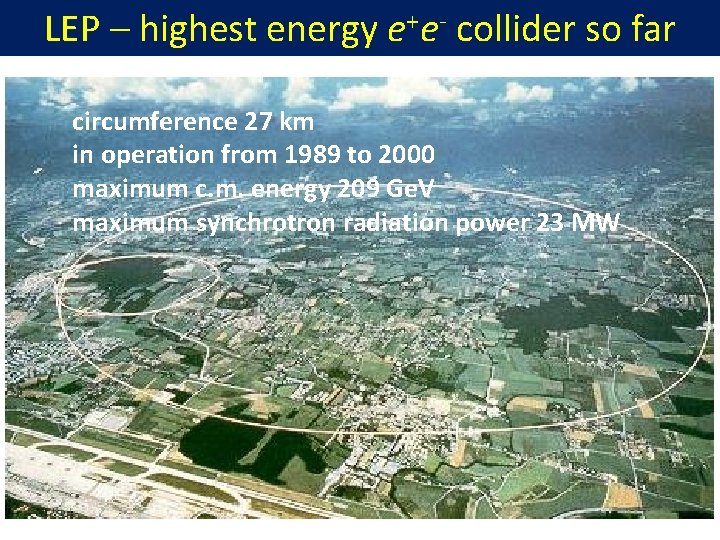
LEP – highest energy e+e- collider so far circumference 27 km in operation from 1989 to 2000 maximum c. m. energy 209 Ge. V maximum synchrotron radiation power 23 MW
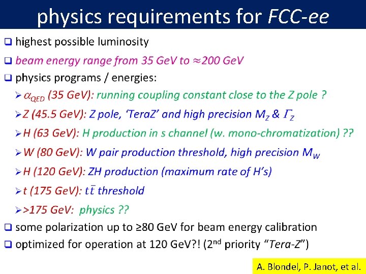
physics requirements for FCC-ee A. Blondel, P. Janot, et al.
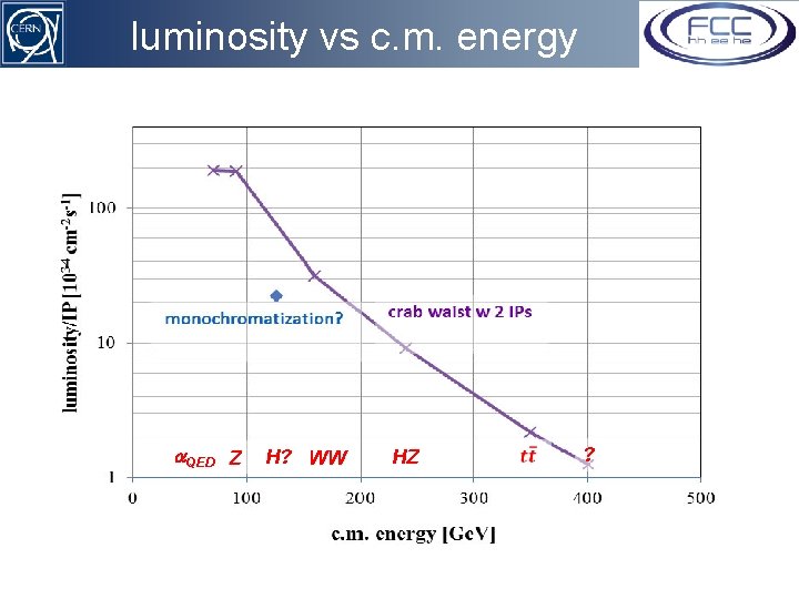
luminosity vs c. m. energy a. QED Z H? WW HZ ?
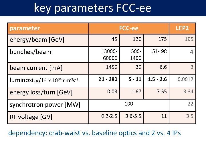
key parameters FCC-ee parameter energy/beam [Ge. V] bunches/beam current [m. A] luminosity/IP x 1034 cm-2 s-1 energy loss/turn [Ge. V] FCC-ee 45 120 175 105 13000 - 60000 500 - 1400 51 - 98 4 1450 30 6. 6 3 21 - 280 5 - 11 1. 5 - 2. 6 0. 0012 0. 03 1. 67 7. 55 3. 34 synchrotron power [MW] RF voltage [GV] LEP 2 100 0. 2 -2. 5 3. 6 -5. 5 22 11 dependency: crab-waist vs. baseline optics and 2 vs. 4 IPs 3. 5
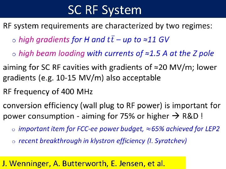
SC RF System J. Wenninger, A. Butterworth, E. Jensen, et al.
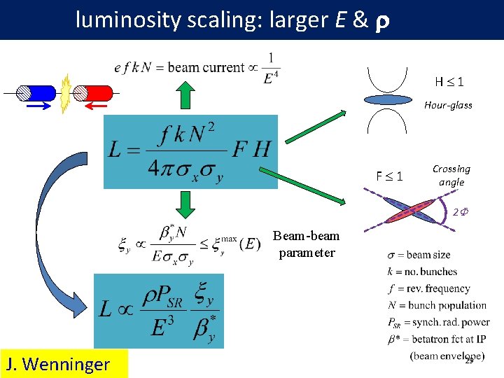
luminosity scaling: larger E & r H 1 Hour-glass F 1 Crossing angle 2 F Beam-beam parameter J. Wenninger 29
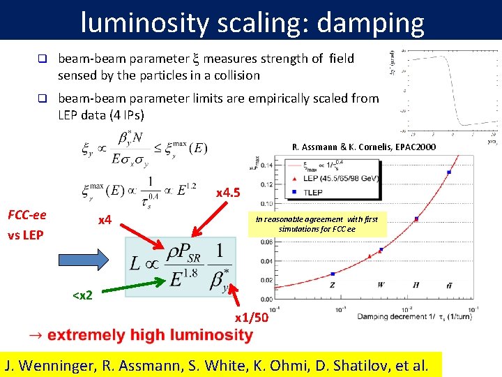
luminosity scaling: damping q beam-beam parameter x measures strength of field sensed by the particles in a collision q beam-beam parameter limits are empirically scaled from LEP data (4 IPs) R. Assmann & K. Cornelis, EPAC 2000 x 4. 5 FCC-ee vs LEP x 4 In reasonable agreement with first simulations for FCC ee <x 2 x 1/50 J. Wenninger, R. Assmann, S. White, K. Ohmi, D. Shatilov, et al.
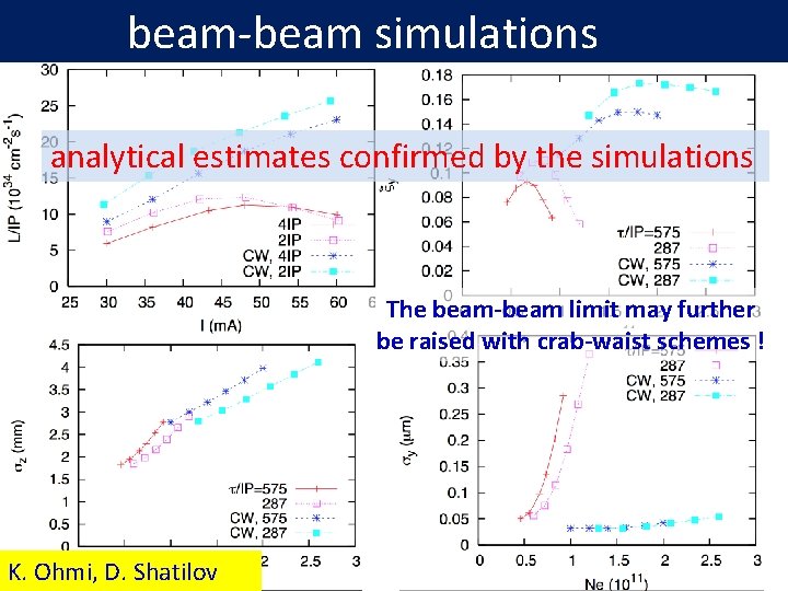
beam-beam simulations analytical estimates confirmed by the simulations The beam-beam limit may further be raised with crab-waist schemes ! K. Ohmi, D. Shatilov
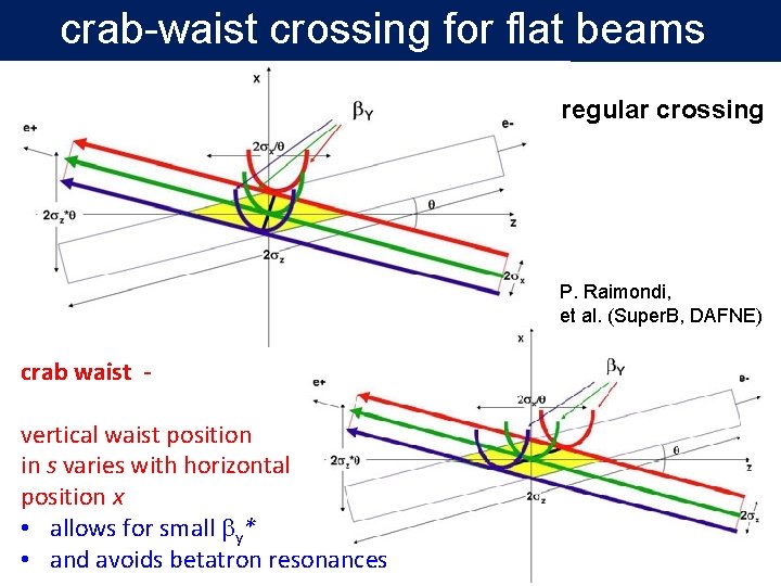
crab-waist crossing for flat beams regular crossing P. Raimondi, et al. (Super. B, DAFNE) crab waist vertical waist position in s varies with horizontal position x • allows for small by* • and avoids betatron resonances
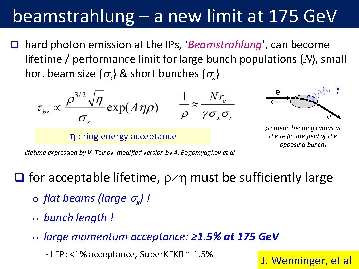
beamstrahlung – a new limit at 175 Ge. V q hard photon emission at the IPs, ‘Beamstrahlung’, can become lifetime / performance limit for large bunch populations (N), small hor. beam size (sx) & short bunches (ss) g e e h : ring energy acceptance lifetime expression by V. Telnov, modified version by A. Bogomyagkov et al q r : mean bending radius at the IP (in the field of the opposing bunch) for acceptable lifetime, r h must be sufficiently large o flat beams (large sx) ! o bunch length ! o large momentum acceptance: ≥ 1. 5% at 175 Ge. V - LEP: <1% acceptance, Super. KEKB ~ 1. 5% J. Wenninger, et al
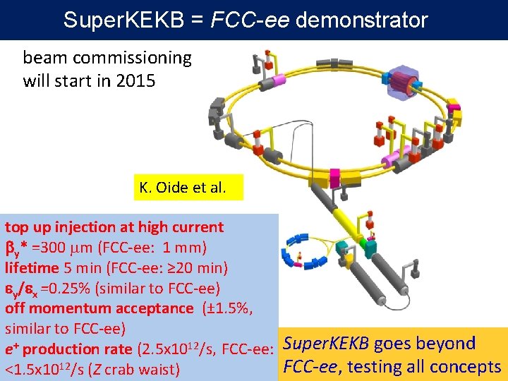
Super. KEKB = FCC-ee demonstrator beam commissioning will start in 2015 K. Oide et al. top up injection at high current by* =300 mm (FCC-ee: 1 mm) lifetime 5 min (FCC-ee: ≥ 20 min) ey/ex =0. 25% (similar to FCC-ee) off momentum acceptance (± 1. 5%, similar to FCC-ee) e+ production rate (2. 5 x 10¹²/s, FCC-ee: Super. KEKB goes beyond FCC-ee, testing all concepts <1. 5 x 10¹²/s (Z crab waist)
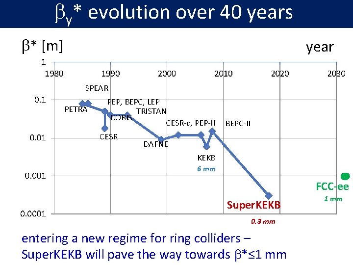
by* evolution over 40 years b* [m] year SPEAR PETRA PEP, BEPC, LEP TRISTAN DORIS CESR-c, PEP-II CESR BEPC-II DAFNE KEKB 6 mm FCC-ee Super. KEKB 0. 3 mm entering a new regime for ring colliders – Super. KEKB will pave the way towards b*≤ 1 mm
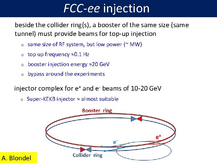
FCC-ee injection beside the collider ring(s), a booster of the same size (same tunnel) must provide beams for top-up injection o same size of RF system, but low power (~ MW) o top up frequency ≈0. 1 Hz o booster injection energy ≈20 Ge. V o bypass around the experiments injector complex for e+ and e- beams of 10 -20 Ge. V o Super-KEKB injector ≈ almost suitable A. Blondel
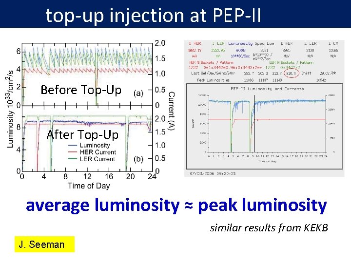
top-up injection at PEP-II Before Top-Up After Top-Up average luminosity ≈ peak luminosity similar results from KEKB J. Seeman
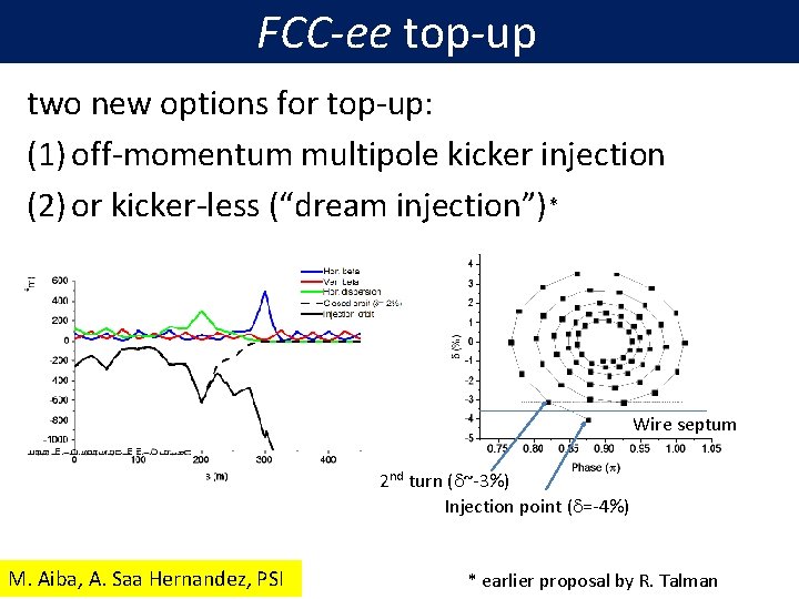
FCC-ee top-up two new options for top-up: (1) off-momentum multipole kicker injection (2) or kicker-less (“dream injection”) * Wire septum 2 nd turn (d~-3%) Injection point (d=-4%) M. Aiba, A. Saa Hernandez, PSI * earlier proposal by R. Talman
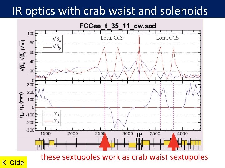
IR optics with crab waist and solenoids K. Oide these sextupoles work as crab waist sextupoles
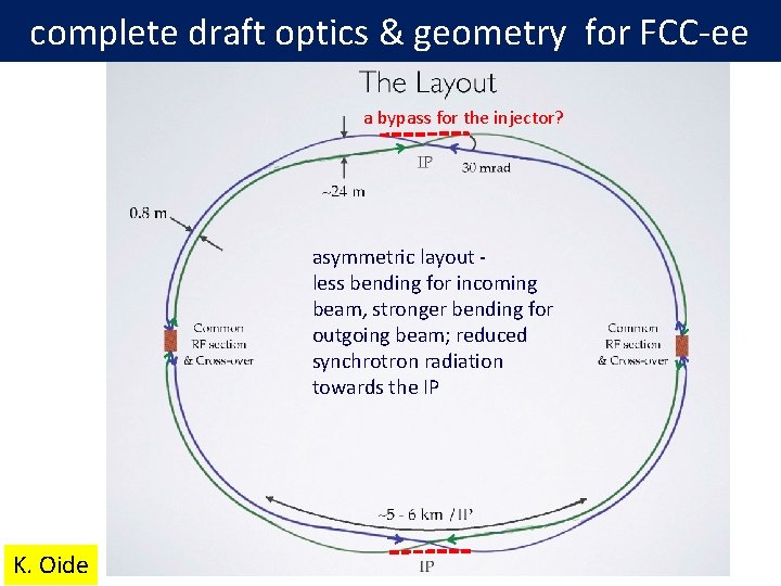
complete draft optics & geometry for FCC-ee a bypass for the injector? asymmetric layout - less bending for incoming beam, stronger bending for outgoing beam; reduced synchrotron radiation towards the IP K. Oide
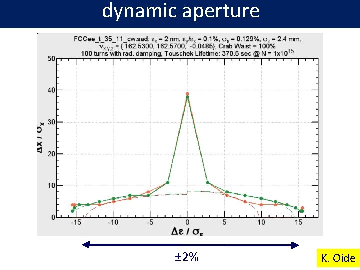
dynamic aperture ± 2% K. Oide
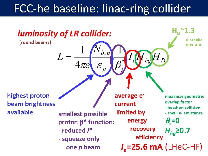
FCC-he baseline: linac-ring collider luminosity of LR collider: (round beams) HD~1. 3 D. Schulte LHe. C 2010 highest proton average emaximize geometric overlap factor beam brightness current - head-on collision available - small e- emittance smallest possible limited by energy qc=0 proton b* function: recovery H ≥ 0. 7 - reduced l* hg efficiency - squeeze only one p beam Ie=25. 6 m. A (LHe. C-HF)
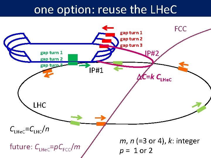
one option: reuse the LHe. C gap turn 1 gap turn 2 gap turn 3 IP#1 FCC IP#2 DC=k CLHe. C LHC CLHe. C=CLHC/n future: CLHe. C=p. CFCC/m m, n (=3 or 4), k: integer p = 1 or 2
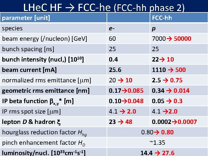
LHe. C HF → FCC-he (FCC-hh phase 2) parameter [unit] species beam energy (/nucleon) [Ge. V] bunch spacing [ns] e 60 25 FCC-hh p 7000→ 50000 25 bunch intensity (nucl, ) [1010] beam current [m. A] normalized rms emittance [mm] 0. 4 25. 6 20 → 10 22→ 10 1110 → 500 2. 5 → 0. 75 geometric rms emittance [nm] IP beta function bx, y* [m] IP rms spot size [mm] lepton D & hadron x hourglass reduction factor Hhg pinch enhancement factor HD luminosity/nucl. [1033 cm-1 s-1] 0. 17→ 0. 085 0. 34 → 0. 014 0. 10→ 0. 048 0. 05 → 0. 3 4. 1 → 2. 0 23 → 48 0. 0002→ 0. 0007 0. 80→ 0. 80 ~1. 35 14. 4 → 27. 6
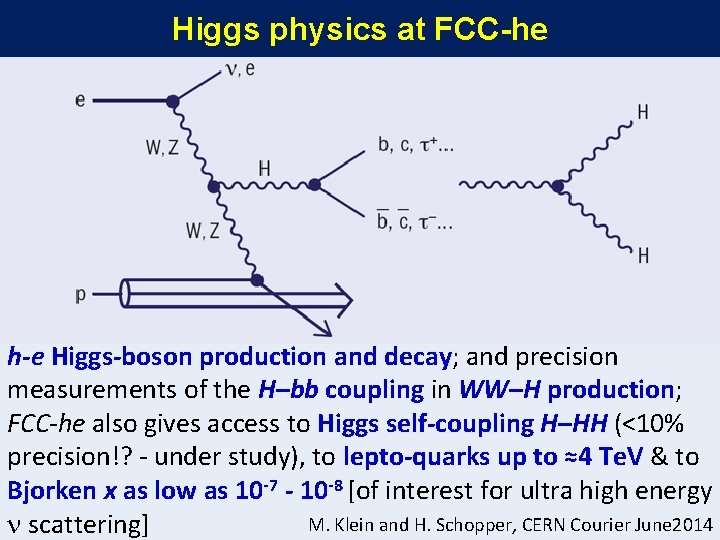
Higgs physics at FCC-he h-e Higgs-boson production and decay; and precision measurements of the H–bb coupling in WW–H production; FCC-he also gives access to Higgs self-coupling H–HH (<10% precision!? - under study), to lepto-quarks up to ≈4 Te. V & to Bjorken x as low as 10 -7 - 10 -8 [of interest for ultra high energy M. Klein and H. Schopper, CERN Courier June 2014 n scattering]
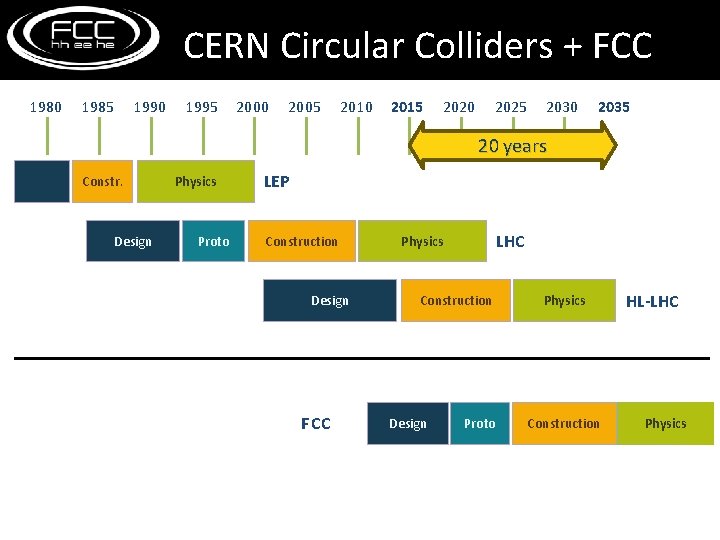
CERN Circular Colliders + FCC 1980 1985 1990 1995 2000 2005 2010 2015 2020 2025 2030 2035 20 years Constr. Design Physics Proto LEP Construction Design FCC LHC Physics Construction Design Proto Physics Construction HL-LHC Physics
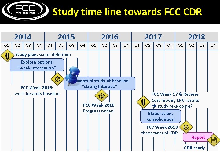
Study time line towards FCC CDR 2014 Q 1 Q 2 Q 3 2015 Q 4 Q 1 Q 2 Q 3 2016 Q 4 Q 1 Q 2 Q 3 2017 Q 4 Q 1 Q 2 Q 3 2018 Q 4 Q 1 Q 2 Q 3 Study plan, scope definition Explore options “weak interaction” FCC Week 2015: work towards baseline conceptual study of baseline “strong interact. ” FCC Week 2016 Progress review FCC Week 17 & Review Cost model, LHC results study re-scoping? Elaboration, consolidation FCC Week 2018 contents of CDR Report CDR ready Q 4
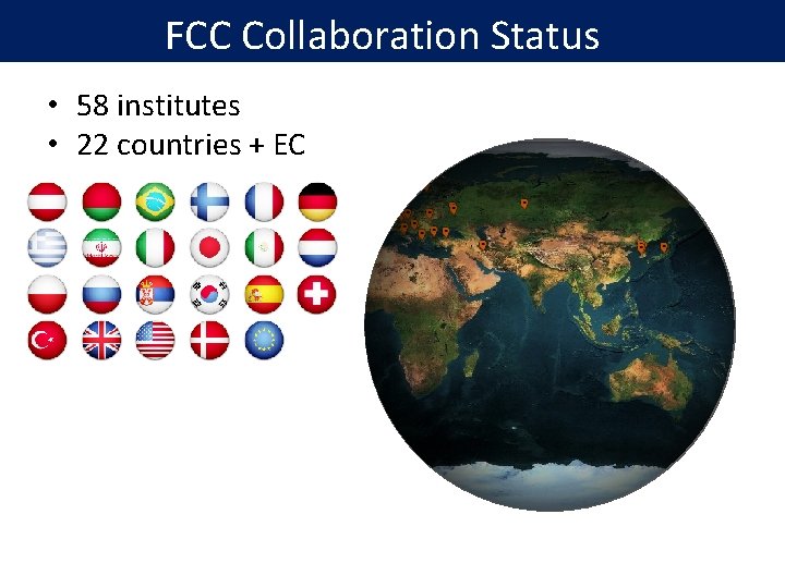
FCC Collaboration Status • 58 institutes • 22 countries + EC
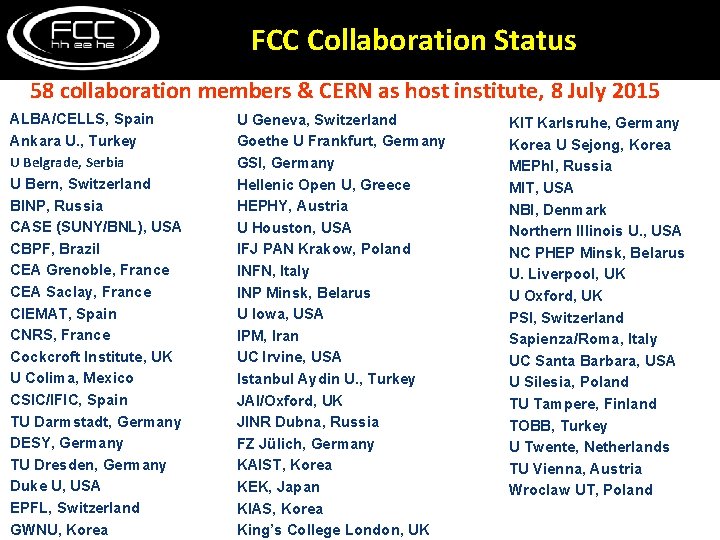
FCC Collaboration Status 58 collaboration members & CERN as host institute, 8 July 2015 ALBA/CELLS, Spain Ankara U. , Turkey U Belgrade, Serbia U Bern, Switzerland BINP, Russia CASE (SUNY/BNL), USA CBPF, Brazil CEA Grenoble, France CEA Saclay, France CIEMAT, Spain CNRS, France Cockcroft Institute, UK U Colima, Mexico CSIC/IFIC, Spain TU Darmstadt, Germany DESY, Germany TU Dresden, Germany Duke U, USA EPFL, Switzerland GWNU, Korea U Geneva, Switzerland Goethe U Frankfurt, Germany GSI, Germany Hellenic Open U, Greece HEPHY, Austria U Houston, USA IFJ PAN Krakow, Poland INFN, Italy INP Minsk, Belarus U Iowa, USA IPM, Iran UC Irvine, USA Istanbul Aydin U. , Turkey JAI/Oxford, UK JINR Dubna, Russia FZ Jülich, Germany KAIST, Korea KEK, Japan KIAS, Korea King’s College London, UK KIT Karlsruhe, Germany Korea U Sejong, Korea MEPh. I, Russia MIT, USA NBI, Denmark Northern Illinois U. , USA NC PHEP Minsk, Belarus U. Liverpool, UK U Oxford, UK PSI, Switzerland Sapienza/Roma, Italy UC Santa Barbara, USA U Silesia, Poland TU Tampere, Finland TOBB, Turkey U Twente, Netherlands TU Vienna, Austria Wroclaw UT, Poland
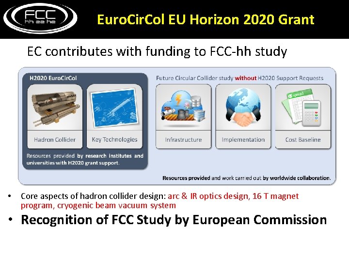
Euro. Cir. Col EU Horizon 2020 Grant EC contributes with funding to FCC-hh study • Core aspects of hadron collider design: arc & IR optics design, 16 T magnet program, cryogenic beam vacuum system • Recognition of FCC Study by European Commission
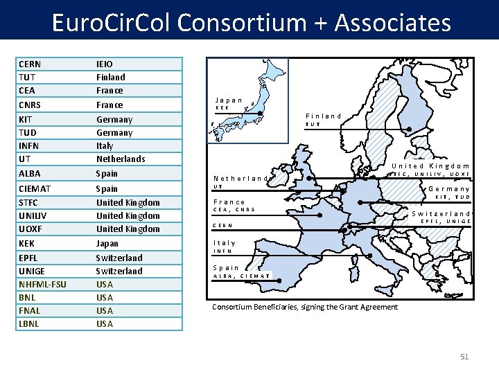
Euro. Cir. Col Consortium + Associates CERN TUT CEA CNRS KIT TUD INFN UT ALBA IEIO Finland France Germany Italy Netherlands Spain CIEMAT STFC UNILIV UOXF KEK EPFL UNIGE NHFML-FSU BNL FNAL LBNL Spain United Kingdom Japan Switzerland USA USA Japan KEK Finland TUT United Kingdom Netherlands STFC, UNILIV, UOXF UT France CEA, CNRS CERN Germany KIT, TUD Switzerland EPFL, UNIGE Italy INFN Spain ALBA, CIEMAT Consortium Beneficiaries, signing the Grant Agreement 51
Conclusions • • bright future for accelerator-based HEP! we now need to urgently prepare for post-LHC period circular hadron collider - only path available in this century towards direct discoveries at 10 s of Te. V energy FCC-hh further develops the new Nb 3 Sn magnet technology of the HL-LHC, it also promotes many other technological innovations (cryogenics, chamber production, …) FCC-ee: attractive intermediate step towards FCC-hh & highly synergetic (infrastructure, time, physics, + SRF) FCC-he: complementary physics, extension of LHe. C great worldwide interest - forming global collaboration
FCC Week 2016 Rome, 11 -15 April 2016
… surely great times ahead!
spare slides
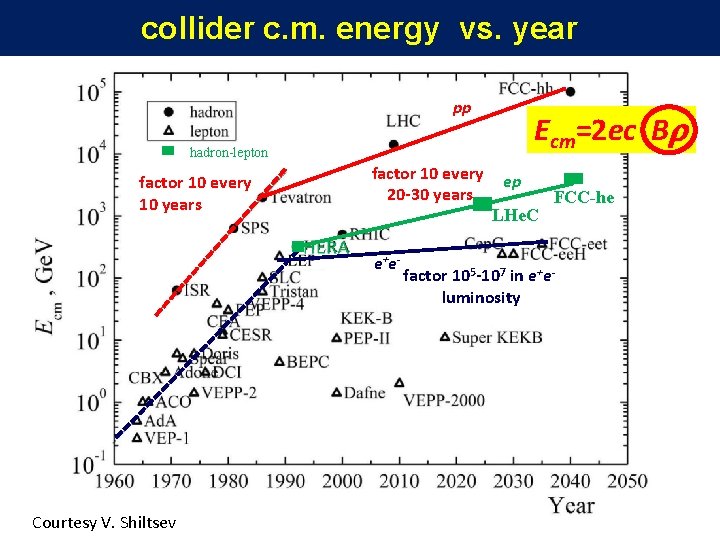
collider c. m. energy vs. year pp Ecm=2 ec Br hadron-lepton factor 10 every 10 years factor 10 every 20 -30 years e+e- Courtesy V. Shiltsev ep LHe. C FCC-he factor 105 -107 in e+eluminosity
FCC-hh: 100 Te. V pp collider Geneva PS SPS LHC 27 km, 8. 33 T 14 Te. V (c. m. ) “HE-LHC” 27 km, 20 T 33 Te. V (c. m. ) FCC-hh (alternative) FCC-hh (baseline) 80 km, 20 T 100 km, 16 T 100 Te. V (c. m. ) L. Bottura B. Strauss