
Further Studies on longitudinal dynamics in the CR


- Slides: 32
Further Studies on longitudinal dynamics in the CR T. Agoh*, D. Alesini, C. Biscari, R. Corsini**, A. Ghigo, LNF, INFN, Frascati *KEK, Japan ** CERN 11 th CTF 3 Collaboration Meeting – 16 -17 January 2007
Contents • CSR in Combiner Ring (Tom Agoh, KEK) • Transverse effects of rf deflectors (David Alesini) • Possible Measurements (Roberto Corsini, Andrea Ghigo)
Previous studies on CSR in CR • Roberto (1999) analytical and simulations for first CR design • Mikhail analytical approach (2001) with present dipoles and chambers To be on the safe path Bunch length of the order of 2 mm to limit energy spread below 1% R 56 tuning chicane
T. Agoh at Frascati for SUPERB studies – Nov 06 has dedicated some time to simulate the CR dynamics and validate the previous analytical approach results Ø CSR calculation using paraxial approximation • Parabolic equation • Comparison with analytic solutions Ø CSR effect in the CTF 3 combiner ring • Wakefield, Impedance, Loss factor • Energy spread growth due to CSR
Numerical method * (1) Begin with Maxwell equations in vacuum (E, B) Time domain : (2) Fourier transform EM field w. r. t z Frequency domain : (3) Approximate these equations in Paraxial approximation (chamber cross section much smaller than radius of curvature) (4) Solve them by finite difference Beam pipe = boundary condition (5) Inverse Fourier transform Back to the time domain *T. Agoh, K. Yokoya, PRST-AB, 7, 054403 (2004)
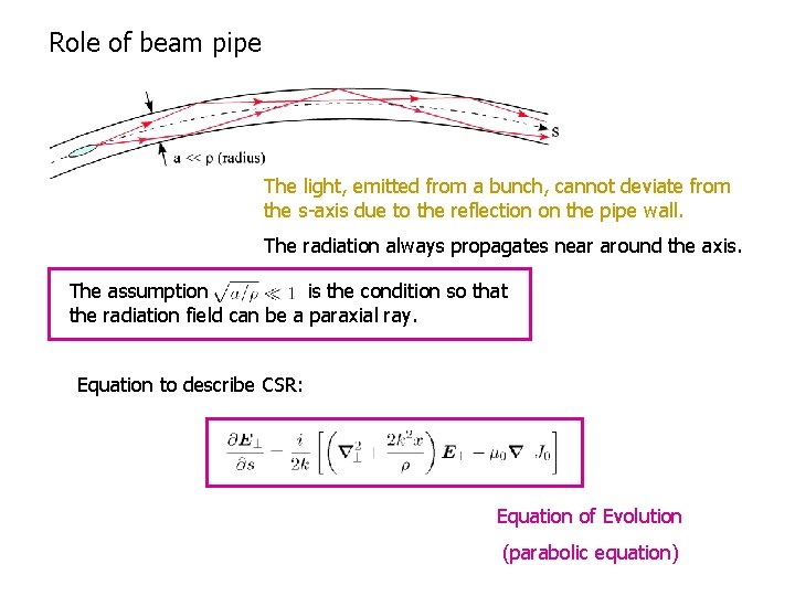
Role of beam pipe The light, emitted from a bunch, cannot deviate from the s-axis due to the reflection on the pipe wall. The radiation always propagates near around the axis. The assumption is the condition so that the radiation field can be a paraxial ray. Equation to describe CSR: Equation of Evolution (parabolic equation)
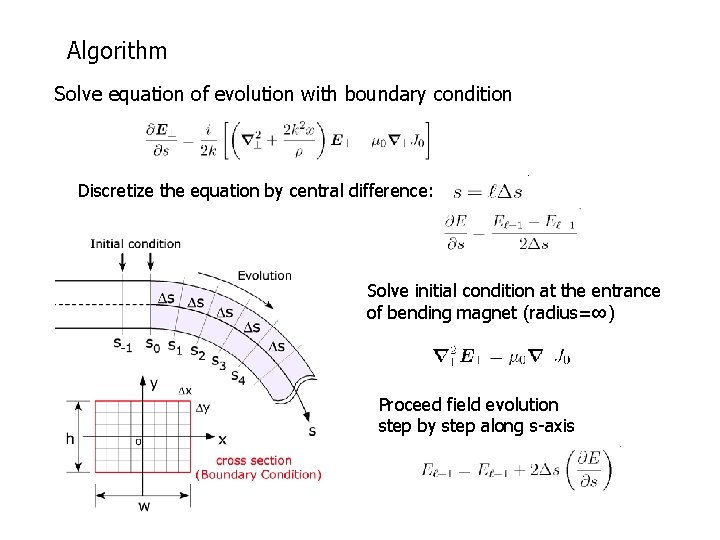
Algorithm Solve equation of evolution with boundary condition Discretize the equation by central difference: Solve initial condition at the entrance of bending magnet (radius=∞) Proceed field evolution step by step along s-axis
Examples to which this approach cannot be applied Ø Free space or very large vacuum chamber • EM field is no longer a paraxial ray. Ø Chamber structure so that backward waves are produced • Bellows, Cavity Chamber wall must be smooth. Ø Ultra-short bunch, or fine structure in the bunch • Fine mesh is required to resolve the field. (expensive) The shortest bunch length I computed is 10 microns in 6 cm pipe. • Bunch profile with sharp edge, e. g. rectangular, triangular, etc Bunch profile must be smooth.
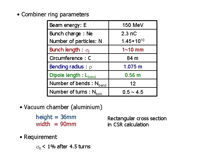
• Combiner ring parameters Beam energy: E 150 Me. V Bunch charge : Ne Number of particles: N 2. 3 n. C 1. 45× 1010 Bunch length : sz 1~10 mm Circumference : C 84 m Bending radius : r 1. 075 m Dipole length : Lbend 0. 56 m Number of bends : Nbend Number of turns : Nturn 12 0. 5 ~ 4. 5 • Vacuum chamber (aluminium) height = 36 mm width = 90 mm • Requirement sd < 1% after 4. 5 turns Rectangular cross section in CSR calculation
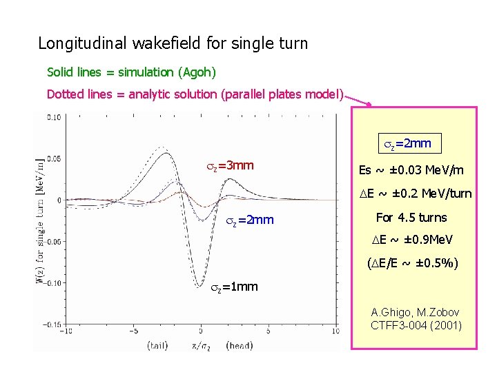
Longitudinal wakefield for single turn Solid lines = simulation (Agoh) Dotted lines = analytic solution (parallel plates model) sz=2 mm sz=3 mm Es ~ ± 0. 03 Me. V/m DE ~ ± 0. 2 Me. V/turn sz=2 mm For 4. 5 turns DE ~ ± 0. 9 Me. V (DE/E ~ ± 0. 5%) sz=1 mm A. Ghigo, M. Zobov CTFF 3 -004 (2001)
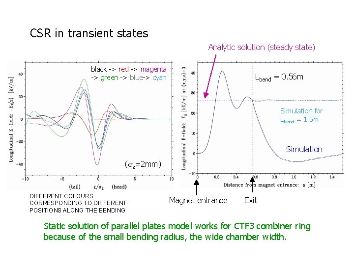
CSR in transient states Analytic solution (steady state) black -> red -> magenta -> green -> blue-> cyan Lbend = 0. 56 m Simulation for Lbend = 1. 5 m Simulation (sz=2 mm) DIFFERENT COLOURS CORRESPONDING TO DIFFERENT POSITIONS ALONG THE BENDING Magnet entrance Exit Static solution of parallel plates model works for CTF 3 combiner ring because of the small bending radius, the wide chamber width.
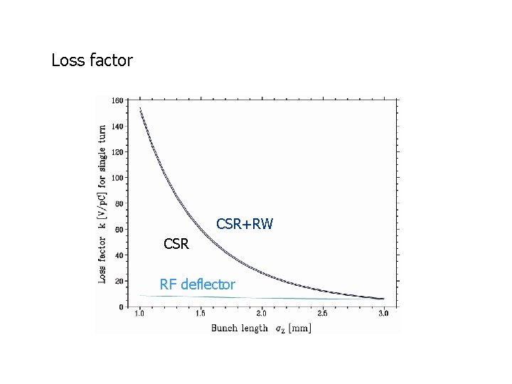
Loss factor CSR+RW CSR RF deflector
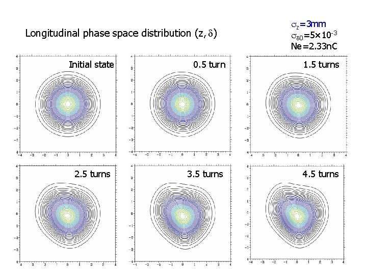
Longitudinal phase space distribution (z, d) Initial state 2. 5 turns sz=3 mm sd 0=5× 10 -3 Ne=2. 33 n. C 0. 5 turn 1. 5 turns 3. 5 turns 4. 5 turns
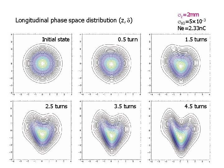
Longitudinal phase space distribution (z, d) Initial state 2. 5 turns sz=2 mm sd 0=5× 10 -3 Ne=2. 33 n. C 0. 5 turn 1. 5 turns 3. 5 turns 4. 5 turns
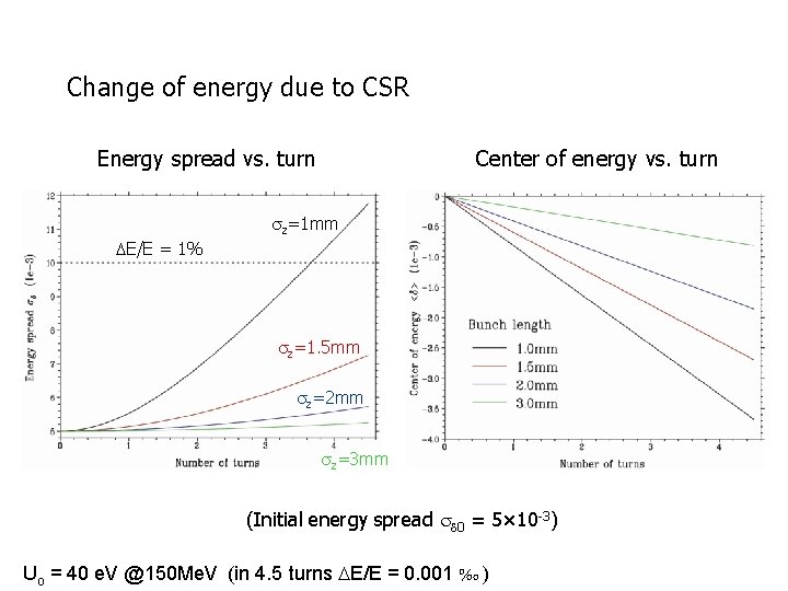
Change of energy due to CSR Energy spread vs. turn Center of energy vs. turn sz=1 mm DE/E = 1% sz=1. 5 mm sz=2 mm sz=3 mm (Initial energy spread sd 0 = 5× 10 -3) Uo = 40 e. V @150 Me. V (in 4. 5 turns DE/E = 0. 001 ‰ )
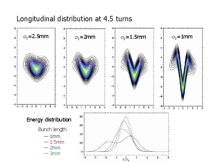
Longitudinal distribution at 4. 5 turns sz=2. 5 mm Energy distribution Bunch length — 1 mm — 1. 5 mm — 2 mm — 3 mm sz=2 mm sz=1. 5 mm sz=1 mm
Energy spread vs. Bunch length sz=1. 2 mm DE/E = 1% sd=9. 4× 10 -3 4. 5 turns If the bunch length is shorter than 1. 2 mm, the energy spread exceeds 1% at 4. 5 turns.
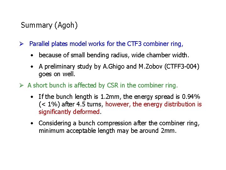
Summary (Agoh) Ø Parallel plates model works for the CTF 3 combiner ring, • because of small bending radius, wide chamber width. • A preliminary study by A. Ghigo and M. Zobov (CTFF 3 -004) goes on well. Ø A short bunch is affected by CSR in the combiner ring. • If the bunch length is 1. 2 mm, the energy spread is 0. 94% (< 1%) after 4. 5 turns, however, the energy distribution is significantly deformed. • Considering a bunch compression after the combiner ring, minimum acceptable length may be around 2 mm.
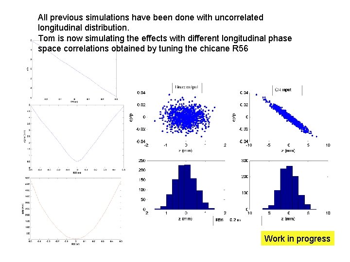
All previous simulations have been done with uncorrelated longitudinal distribution. Tom is now simulating the effects with different longitudinal phase space correlations obtained by tuning the chicane R 56 Work in progress
Missing: start to end simulations for overall beam dynamics behaviour • Longitudinal plane : linac acceleration, csr, wake fields, RF deflector effects, non-linear isochronicity, CSR • Transverse plane: transverse non linearities, betatron beating from mismatch, chromaticity, high order terms, …
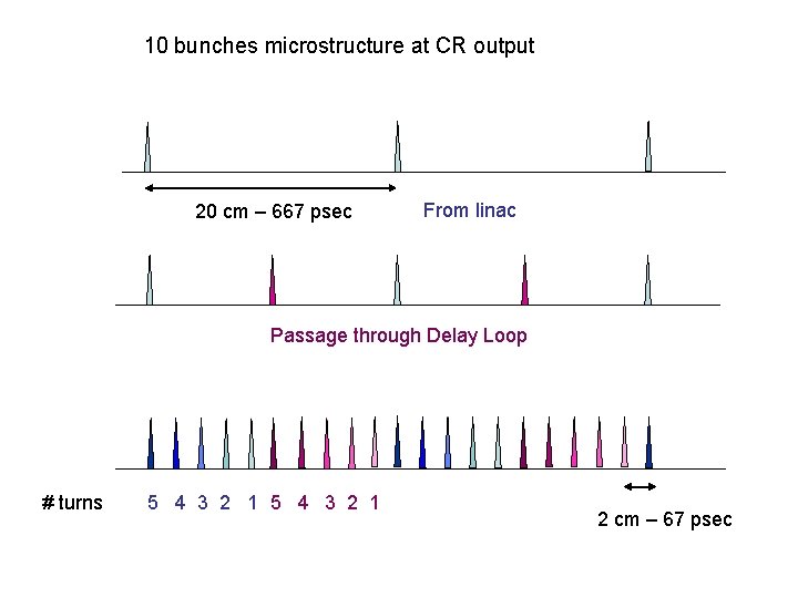
10 bunches microstructure at CR output 20 cm – 667 psec From linac Passage through Delay Loop # turns 5 4 3 2 1 2 cm – 67 psec
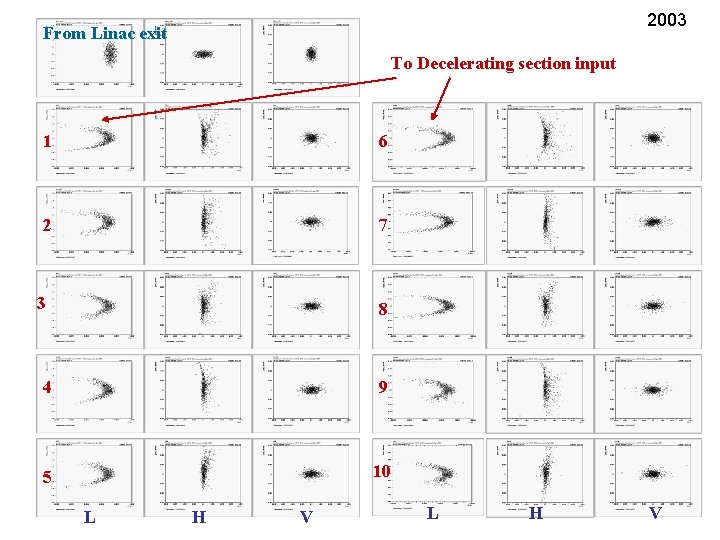
2003 From Linac exit To Decelerating section input 1 6 2 7 3 8 4 9 5 10 L H V
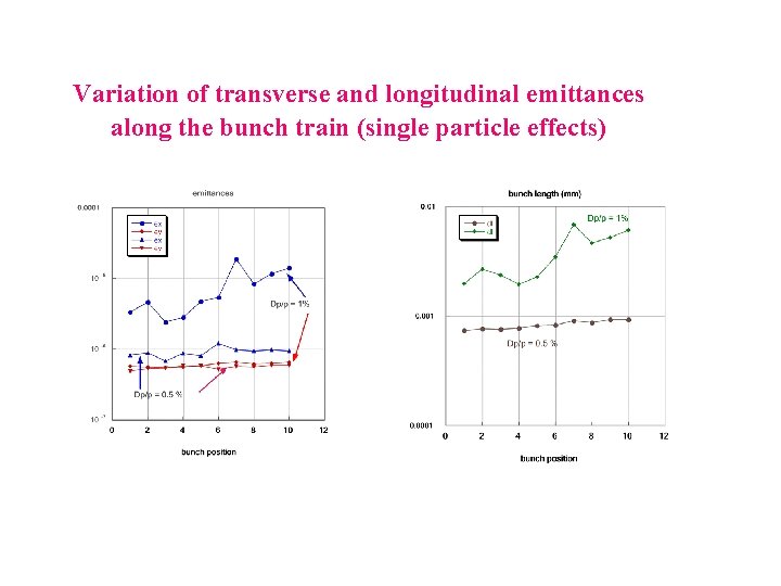
Variation of transverse and longitudinal emittances along the bunch train (single particle effects)
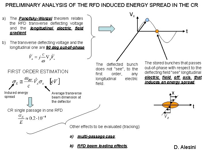
PRELIMINARY ANALYSIS OF THE RFD INDUCED ENERGY SPREAD IN THE CR Vx a) The Panofsky-Wenzel theorem relates the RFD transverse deflecting voltage and the longitudinal electric field gradient; t b) The transverse deflecting voltage and the longitudinal one are 90 deg out-of-phase The deflected bunch does not “see”, to the first order, any longitudinal electric field. FIRST ORDER ESTIMATION Induced energy spread The stored bunches that passes out-of-phase with respect to the deflecting field “see” longitudinal electric field off axis that induces an energy spread. x Average transverse beam dimension at the deflector t CR single passage in one RFD Vz Other effects to be evaluated (tracking): a) multi-passage case; b) RFD beam loading effects; D. Alesini
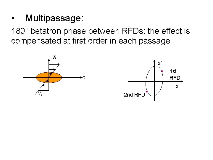
• Multipassage: 180° betatron phase between RFDs: the effect is compensated at first order in each passage X x’ 1 st RFD t x Vz 2 nd RFD
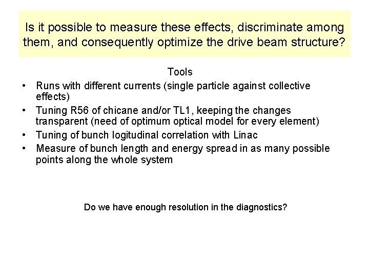
Is it possible to measure these effects, discriminate among them, and consequently optimize the drive beam structure? • • Tools Runs with different currents (single particle against collective effects) Tuning R 56 of chicane and/or TL 1, keeping the changes transparent (need of optimum optical model for every element) Tuning of bunch logitudinal correlation with Linac Measure of bunch length and energy spread in as many possible points along the whole system Do we have enough resolution in the diagnostics?
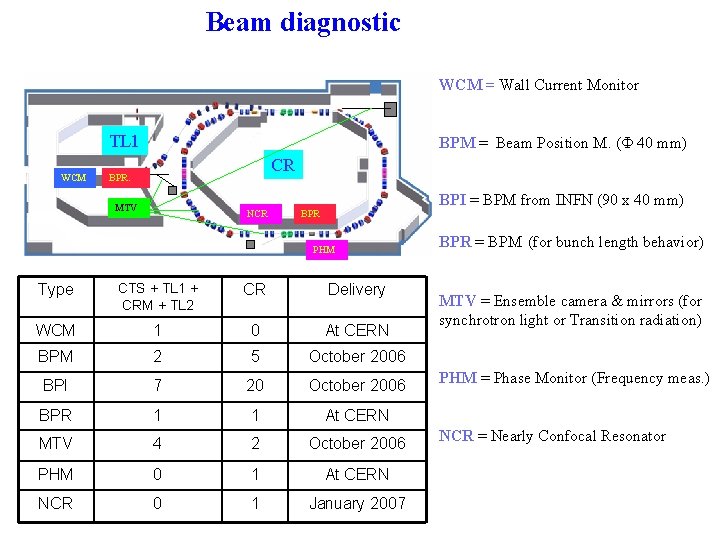
Beam diagnostic WCM = Wall Current Monitor TL 1 WCM BPM = Beam Position M. ( 40 mm) CR BPR. MTV NCR BPI = BPM from INFN (90 x 40 mm) BPR PHM Type CTS + TL 1 + CRM + TL 2 CR Delivery WCM 1 0 At CERN BPM 2 5 October 2006 BPI 7 20 October 2006 BPR 1 1 At CERN MTV 4 2 October 2006 PHM 0 1 At CERN NCR 0 1 January 2007 BPR = BPM (for bunch length behavior) MTV = Ensemble camera & mirrors (for synchrotron light or Transition radiation) PHM = Phase Monitor (Frequency meas. ) NCR = Nearly Confocal Resonator
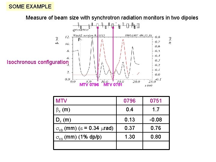
SOME EXAMPLE Measure of beam size with synchrotron radiation monitors in two dipoles Isochronous configuration MTV 0796 MTV 0751 MTV 0796 0751 bx (m) 0. 4 1. 7 Dx (m) 0. 13 -0. 08 sxb (mm) (e = 0. 34 mrad) 0. 37 0. 76 sxs (mm) (1% dp/p) 1. 30 0. 80
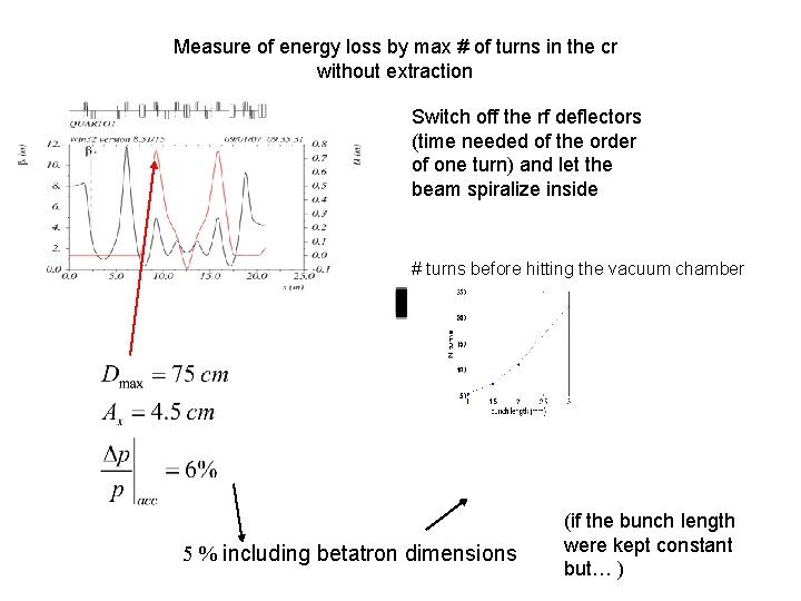
Measure of energy loss by max # of turns in the cr without extraction Switch off the rf deflectors (time needed of the order of one turn) and let the beam spiralize inside # turns before hitting the vacuum chamber 5 % including betatron dimensions (if the bunch length were kept constant but… )
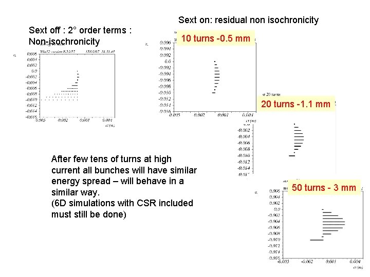
Sext off : 2° order terms : Non-isochronicity Sext on: residual non isochronicity 10 turns -0. 5 mm 20 turns -1. 1 mm After few tens of turns at high current all bunches will have similar energy spread – will behave in a similar way. (6 D simulations with CSR included must still be done) 50 turns - 3 mm
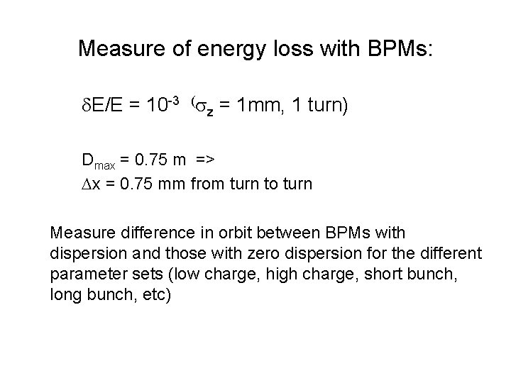
Measure of energy loss with BPMs: d. E/E = 10 -3 (sz = 1 mm, 1 turn) Dmax = 0. 75 m => Dx = 0. 75 mm from turn to turn Measure difference in orbit between BPMs with dispersion and those with zero dispersion for the different parameter sets (low charge, high charge, short bunch, long bunch, etc)
Conclusions • Beam dynamics calculations in progress (Cern, KEK, Frascati, …) • Main aim: find the best configuration for power production • Opportunity to use the 2007 commissioning as a test bench for emittance preservation, csr studies, . . applicable to other accelerators