Furnace aa Do you like spaghetti Electrothermal Analyzer


 Graphite Furnace • A hollow graphite tube which is purged with")


 is available for")


- Slides: 48
Furnace aa
Do you like spaghetti?
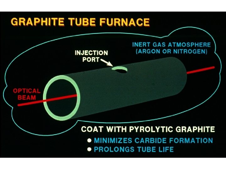
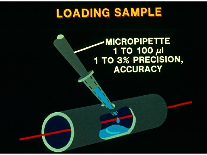
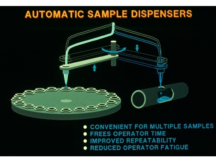
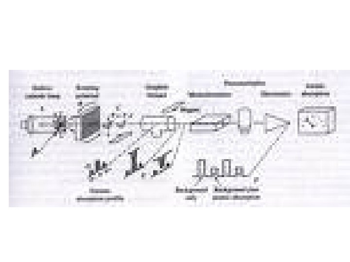
Electrothermal Analyzer (ETA) Graphite Furnace • A hollow graphite tube which is purged with inert gas, usually Argon, to prevent oxidation of tube • Positioned so light passes through tube • Liquid samples are added through injection hole • Solid samples are put in in grahite boat • Sample introduction = least precise step – may introduce contamination
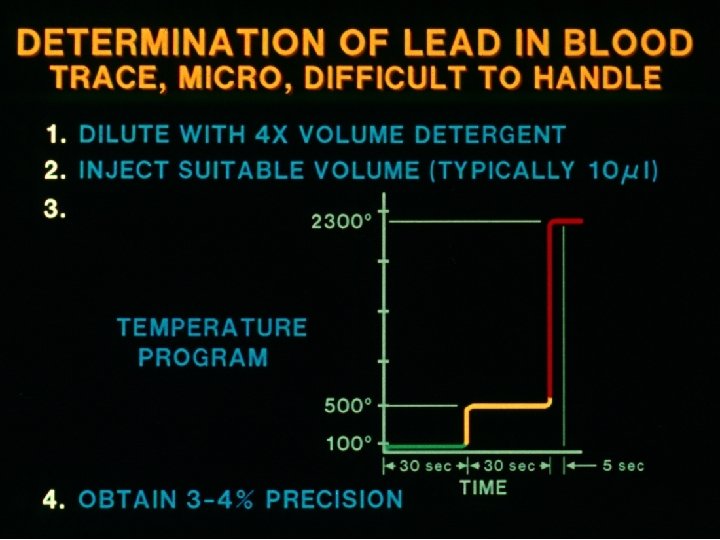
L’vov platform furnace • Sample is placed on platform • Temp of platform rises more slowly than that of walls • Atomization is delayed until temp within furnace is nearly constant • Helps eliminate matrix effects
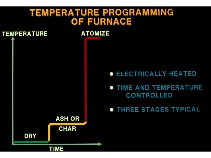
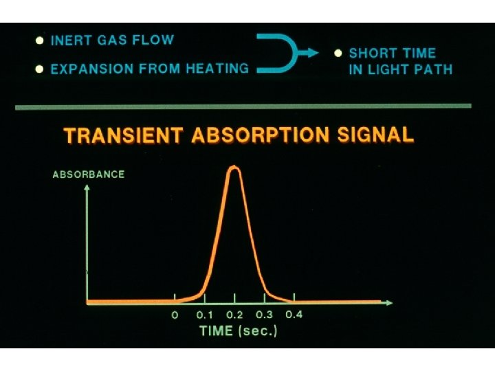
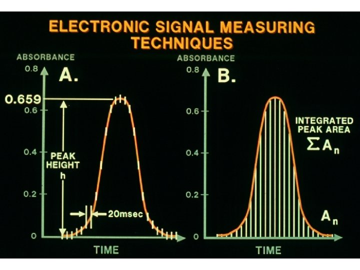
Third Stage -Atomization • Temperature depends on the element • Generally 1000 – 3000 o. C • The atoms have a very short residence time in the light path because they diffuse easily • The inert gas flow is often stopped briefly at this point so that sample is not flushed away too quickly
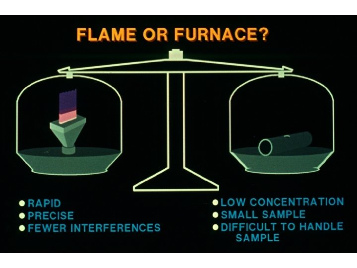
Absorption • Measured during atomization • Want fast atomization so there is a large concentration of free atoms • Transient signal as compared to continuous from flame • Detects 10 -10 – 10 -13 g sample • Relative precision 5 -10% • Usually need background correction because of matrix interference
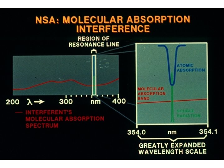
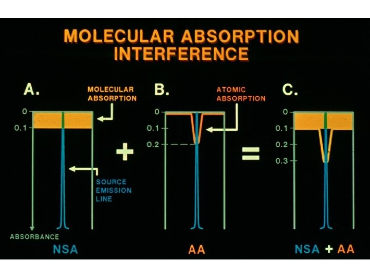
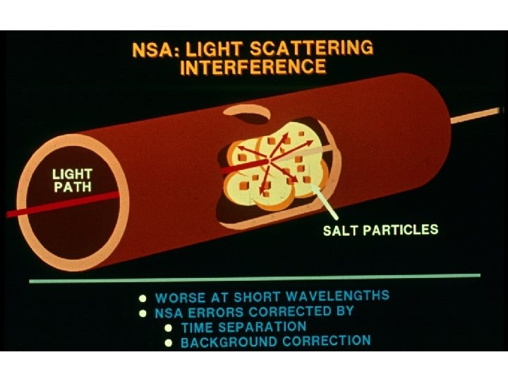
NSA- a particular problem in furnaces • The interference is non-atomic and therefore broad • It arises from – Molecular absorption – Light scattering • Worse in furnace than flame because the molecules are not decomposed as thoroughly in the furnace – flame has heat and chemistry
Two-line Correction Method • A line from HCL can be used as reference – but can’t be absorbed by sample • Must be near analyte line • From Ne or Ar or impurity • Suitable line often not available
Continuum Source Correction Method • D 2 lamp provides continuum of radiation • Passes through sample alternately with light from HCL (via chopper) • Fraction of continuum absorbed by atoms is negligible • Therefore gives • absorbance by • background
Zeeman Background Correction • Zeeman applies to the shifting of energy levels of atoms & molecules which occurs in a magnetic field. When atomic vapour is exposed to a strong magnetic field, a splitting of electronic energy levels of atoms occurs. • This forms several absorbance lines for each electronic transition. • The sum of the absorbance for all these lines is equal to the absorbance of the original unshifted line. • When a magnetic field is applied parallel to the light path through a flame or furnace, the absorption line is split into 3 lines. • The central line has the original wavelength with an absorbance twice that of the satellite line.
The Zeeman Effect is based on the differing response of these two types of absorbance peaks to polarised radiation. The control line only absorbs radiation that is plane polarised in a direction parallel to the external magnetic field. In contrast the satellite peaks absorb radiation polarised at 90 degrees to the field.
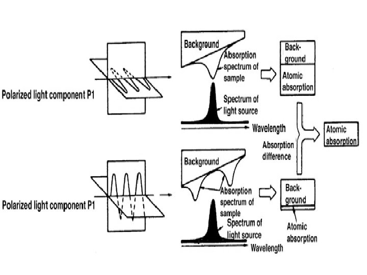
• Light from the HCL is passed through a rotating polariser, which separates the beam into 2 components, plane polarised at 90 degrees to one another. • These beams pass through the atom cell, which has a magnetic field applied, resulting in shift of absorbancies. • When incident radiation is plane polarised in a direction parallel to magnetic field, the central line can absorb the radiation. Absorbance is due to the analyte metal & background absorbance.
• When incident radiation is polarised at 90 degrees to direction of applied field, the central line no longer absorbs. But back ground still absorbs. • The data aquisition system is programmed to subtract the two signals giving the corrected signal.
Advantages of Zeeman and Smith. Hieftje over Background Correction • • Background corrected more accurately Corrected at close to absorption Don’t need extra lamp Single light source eliminates alignment problems • Can correct to higher levels of NSA
Disadvantages • • Some loss of sensitivity for most elements Greater calibration curvature Increased cost for Zeeman Smith-Hieftje requires additional power supply and may reduce lamp life
• http: //www. shsu. edu/~chm_tgc/sounds/so und. html
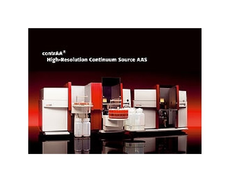
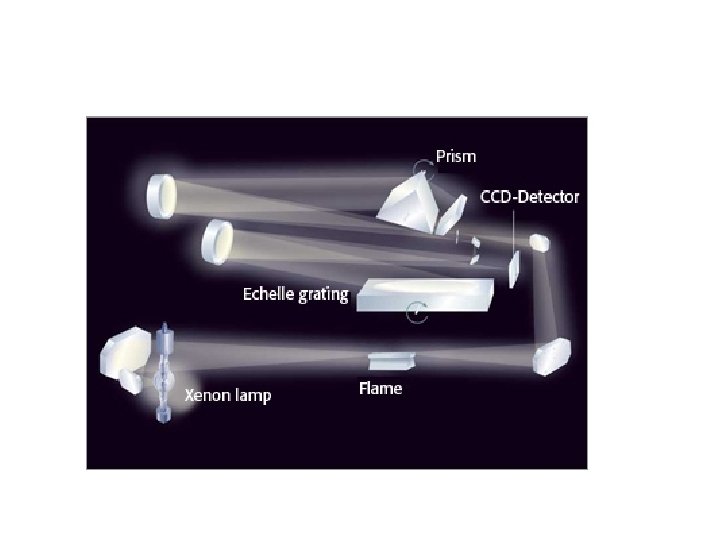
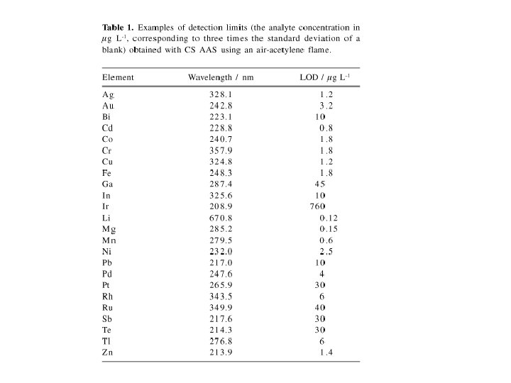
Continuum Source AAS • High Resolution Continuum Source AAS (HR-CS AAS) is available for both flames and graphite furnaces • Single Xenon Arc Lamp – High Intensity so better S/N ratio so lower LOD – up to 10 times lower than conventional AAS.
Echelle monochromator • Made up of two dispersing elements – an echelle grating and a prism in series. • Uses higher orders of light- gets high resolution
• The radiation emitted by the continuum radiation source, after its attenuation in the atomization unit, is conducted to the double monochromator, which consists of an entrance slit, a prism pre-monochromator, an intermediate slit and an echelle grating monochromator. The intermediate slit has to separate the part of the spectrum that contains the analytical line. That part enters the second monochromator, where it is highly resolved. The second monochromator does not have an exit slit, so that the entire part of the spectrum transmitted by the intermediate slit reaches the detector, a linear CCD array that not only detects the analytical line, but also its spectral environment at high resolution.
CCD array detector • Reverse-biased photodiodes discharge a capacitor at a rate proportional to the photon flux • When the integration period of the detector is complete, a series of switches closes and transfers the charge to a shift register.
• After the transfer to the shift register is complete, the switches open and the capacitors attached to the photodiodes are recharged and a new integration period begins. • At the same time that light energy is being integrated, the data is read out of the shift register by an A/D converter. The digitized data is then displayed on your computer.
Correction for Flicker Noise • Shows marine sediment reference material around line for Tl at 276. 787 nm • a) Abs over time and λ • b) after correction for all events that were recorded identically by all pixels
• Can analyse 10 elements/minute • Use CCD detectors • Background measured simultaneously