Fundamentals of IT Westminster International University in Tashkent


")


")
")

 that a computer microprocessor can access more")


- Slides: 34
Fundamentals of IT Westminster International University in Tashkent 2015 -2016 Lecture 5: Computer systems architecture
Fundamentals of IT Westminster International University in Tashkent 2011 Arrangements • EC and BIS 3 group will have a substitute tutor this week • BA – need 2 -3 Supermen tomorrow. . . to carry in the processors from IT • COURSEWORK finally on the intranet – 40% – Deadline: 3 March 2016
Layers of Computing Systems Communications Applications Operating Systems Programming Hardware Information
Something familiar. . . Hardware
Fundamentals of IT Westminster International University in Tashkent 2015 -2016 Lecture Outline • Logical structure of Computer System • Computer Architecture – Levels within computer architecture – Physical organization of the computer – Main components of digital logic layer – Processor – Control unit – ALU
Fundamentals of IT Westminster International University in Tashkent 2015 -2016 Logical structure of Computer System
Fundamentals of IT Westminster International University in Tashkent 2011 Computer Architecture: Basic Levels 7 SOFTWARE LEVEL 6 5 4 3 2 1 HARDWARE LEVEL
Fundamentals of IT Westminster International University in Tashkent 2011 Computer Architecture: Levels in detail 7 SOFTWARE LEVEL Application Layer 6 Higher-Order Software Layer 5 Operating System Layer 4 HARDWARE LEVEL Machine Layer 3 Microprogrammed Layer 2 Digital Logic Layer 1 Physical Device Layer • Arrange following in the table: – Physical Device Layer – Application Layer – Microprogrammed Layer – Higher-Order Software Layer – Operating System Layer – Machine Layer – Digital Logic Layer
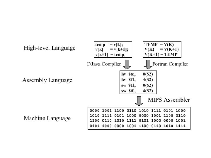
Fundamentals of IT Westminster International University in Tashkent 2011 Computer Architecture: Levels in detail 7 SOFTWARE LEVEL Application Layer 6 Higher-Order Software Layer 5 Operating System Layer 4 HARDWARE LEVEL Machine Layer • Machine language instructions 3 Microprogrammed Layer • Interprets the machine language instructions and directly causes the digital logic elements to perform operations 2 Digital Logic Layer • Gates that are combined onto a single chip 1 Physical Device Layer • Transistors • Capacitors • Resistors
Fundamentals of IT Westminster International University in Tashkent 2011 Physical organisation of the computer • Modular construction • Many different microcomputers contain the same microprocessors • Bus – collection of parallel electrical conductors called “lines” onto which a number of components may be connected – Internal buses – External buses
Physical organisation of the computer (processor)
Physical organisation of the computer
Fundamentals of IT Westminster International University in Tashkent 2011 Physical organisation of the computer • Buses convey: – – Data signals Data address signals Control signals Power • Bus lines – Data lines (Data bus) – Address lines (Address bus) – Control lines (Control bus)
Fundamentals of IT Westminster International University in Tashkent 2011 Physical organisation of the computer • Single-chip computers • Single-board computers – Small general-purpose microcomputers (ex. basic PC) – Small special-purpose computers (ex. Systems controlling small-scale chemical distillation plant) • Multiple-board, bus-based computers
Fundamentals of IT Westminster International University in Tashkent 2011 Processor • Functions – To control the use of main storage to store data and instructions – To control the sequence of operations – To give commands to all parts of the computer system – To carry out processing • Consists of two primary elements – Control Unit (CU) – Arithmetic and Logic Unit (ALU)
Fundamentals of IT Westminster International University in Tashkent 2011 Example of Bus connections MDR – Memory Data Register MAR – Memory Address Register MBR -
Fundamentals of IT Westminster International University in Tashkent 2011 Example of Bus connections
Fundamentals of IT Westminster International University in Tashkent 2011 Example of Bus connections
Fundamentals of IT Westminster International University in Tashkent 2011 Processor • Registers – special-purpose temporarystorage locations within the processor or other devices • Types of registers – Memory Address Register (MAR) – Memory Data Register (MDR) – Memory Buffer Register (MBR) – Data Buffer Registers
Fundamentals of IT Westminster International University in Tashkent 2011 Processor • Memory Data Register (MDR) – Handles all data and instructions passing in and out of the processor • Memory Buffer Register (MBR) – Handles all data and instructions passing in and out of main storage • Memory Address Register (MAR) – Handles location addresses (source/destination) during transfer between the MDR and MBR • Data Buffer Registers – Exists in I/O units connected to the processor and have similar purpose to the MBR
Fundamentals of IT Westminster International University in Tashkent 2011 Details of a processor
Fundamentals of IT Westminster International University in Tashkent 2011 Processor registers • Registers in the processor are constructed so that their contents can be accessed and altered much faster than the contents of locations of main storage
Fundamentals of IT Westminster International University in Tashkent 2011 Processor registers • IR (Instruction Register) – Holds an instruction to be executed which was first taken from main storage via the MDR and placed in). There it is rapidly decoded and performed • DR (Data Registers) within ALU – Hold data to be processed that was taken from main memory via MDR. The required arithmetic or logic operation is rapidly performed. ALU provides result in one DR from which it is taken and stored in main storage • AR (address registers) – hold addresses from Memory Address Register (MAR) • STATUS register – is used by the control unit as a means of detecting conditions which have occurred such as the ALU detecting the arithmetic error of division by zero.
Fundamentals of IT Westminster International University in Tashkent 2011 Control Unit • Is a nerve centre of the computer – Coordinates and controls all-hardware operations (ie, those of peripheral units, main memory and the processor itself)
Fundamentals of IT Westminster International University in Tashkent 2011 Control Unit operation • Fetch-execute cycle – Control unit causes the requisite instruction to be fetched from main storage via the MDR and placed in IR. When main storage receives an appropriate signal from the control unit it transfers the instruction, whose address is specified in the MAR, into the processor’s MDR via the data bus – The control unit interprets the instruction in the IR and causes the instruction to be executed by sending command signals to the appropriate hardware devices.
Fundamentals of IT Westminster International University in Tashkent 2011 Control Unit – Control of sequence of instructions • PC (Program Counter) or SCR (Sequence Control Register) registers – Hold the location address of the next instruction to be performed
Fundamentals of IT Westminster International University in Tashkent 2011 Control Unit – Pipelining • Is a method of speeding up the fetchexecute cycle by fetching not just the next instruction but the next few that follow it in main storage. The instructions are placed in a queue of registers feeding into the IR.
Fundamentals of IT Westminster International University in Tashkent 2011 Arithmetic and logic unit (ALU) • Functions – Carries out the arithmetic (add, substract, multiply and divide) – Performs certain “logical operations” (testing whether two data items match)
Fundamentals of IT Westminster International University in Tashkent 2011 Arithmetic and logic unit (ALU) operation 1. Loading data into the data register from main storage – Data items to be processed are taken from main storage, as directed by the control unit, and pass via the MDR into the data registers in the ALU, where they are stored. 2. ALU performs the required operation(s) on the data (eg. adding) as directed by control unit. The ALU leaves the result in a data register. While such ALU is carrying out an operation it may make use of other registers of its own such as “OPERAND” and “RESULT” 3. Storing data (the result) – Results are taken from data registers and placed in main storage under the control unit signal.
Performance and cost
Cache • is random access memory (RAM) that a computer microprocessor can access more quickly than it can access regular RAM. • LFU (Least Frequently Used) and LRU (Least Recently Used) • The difference is that determining which data items to overwrite.
Fundamentals of IT Westminster International University in Tashkent 2011 Reading • C. S. French “Computer Science”, 5 th edition, Chapter 13 • Dale, “Computer Science Illuminated”, Chapter 5
POWER POINT TEMPLATE Company's new low-cost and easy-to-use Web-site design tool will help entrepreneurs spiff up their online. THANK YOU !!