Fundamentals of Electrochemistry CHEM7234 CHEM 720 Lecture 4


![Example: I=? V=I*R I = 0. 5 [A] I=V/R I = 9 [V] /](https://slidetodoc.com/presentation_image_h/d193b4d0749e465b598e978cb7db66d6/image-4.jpg "Example: I=? V=I*R I = 0. 5 [A] I=V/R I = 9 [V] /")


 Vc max = XC. Imax")


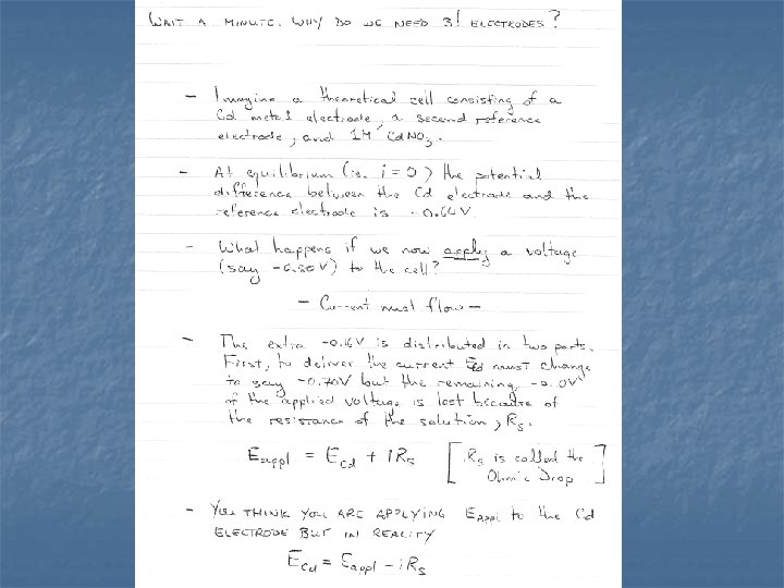
 What are they and why do we need them ? -")
 has high")

 Rin = Rout")


, counter electrode and reference electrode")


 response of a good and (b) bad reference electrode.")
 the most popular R.")


: W. E.")
:")
- Slides: 53
Fundamentals of Electrochemistry CHEM*7234 / CHEM 720 Lecture 4 INSTRUMENTATION
OHM'S LAW Ohms law, or more correctly called Ohm's Law, named after Mr. Georg Ohm, German mathematician and physicist (b. 1789 - d. 1854), defines the relationship between voltage, current and resistance.
Where: V = Voltage I = Current R = Resistance or V=I·R V/I = R
Example: I=? V=I*R I = 0. 5 [A] I=V/R I = 9 [V] / 18 [Ω]
Series connection I = I 1 = I 2 = I 3 Vtotal = V 1 + V 3 Since V = I R, then and Vtotal = I 1 R 1 + I 2 R 2 + I 3 R 3 Vtotal = I Rtotal Setting both equations equal, we get: I Rtotal = I 1 R 1 + I 2 R 2 + I 3 R 3 We know that the current through each resistor (from the first equation) is just I. so I Rtotal = I(R 1 + R 2 + R 3) Rtotal = R 1 + R 2 + R 3
Parallel connection Kirchhoff’s Current Law states that Itotal = I 1 + I 2 + I 3 from Ohm’s Law Itotal = V 1/R 1 + V 2/R 2 + V 3/R 3 but V 1 = V 2 = V 3 = V and Itotal = V/Rtotal gives us:
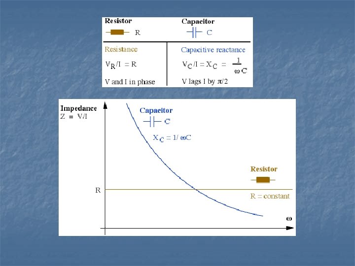
Capacitors where: Vc – voltage across the capacitor qc – charge stored C – capacitance
Vc = Xc · Imax (sin t - /2) Vc max = XC. Imax n n there is 90º difference in phase between current and voltage Xc is called capacitive reactance Xc = 1/( C) = 1/(2 f. C) Xc – a frequency dependent resistor
Impedance, resistance and reactance n n n Impedance, Z, is the general name we give to the ratio of voltage to current. Resistance, R, is a special case of impedance where voltage and current are NOT phase shifted relative to each other. Reactance, Xc, is an another special case in which the voltage and current are out of phase by 90° Generalized Ohm’s Law V=I·Z
RC circuit Because of the 90º phase shift between VC and VR the resistance and capacitive reactance add according to vector addition !!! so Z 2 RC = R 2 + XC 2
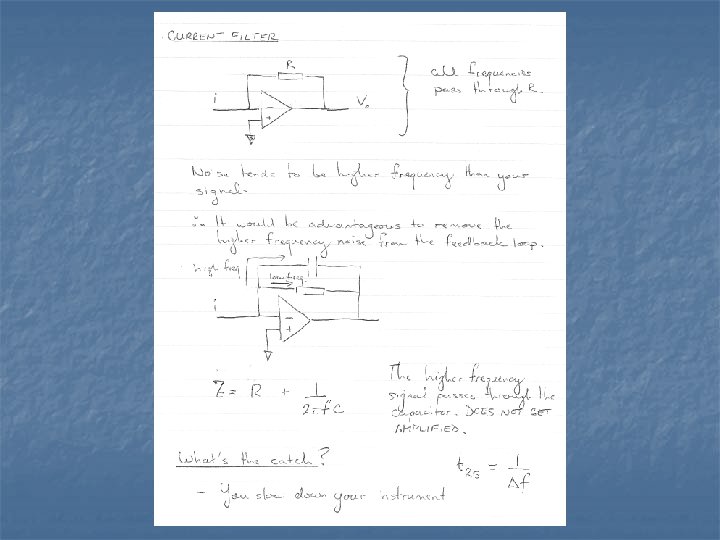
Low Pass Filter Vin = ZRC· I and Vout = XC · I
f XC Z small large XC Vout Vin f XC XC/Z large small Vout 0
For LPF with R = 10 k and C = 0. 1 µF
High Pass Filter Vin = ZRC· I and Vout = R · I
f XC Z small large XC Vout 0 f XC Z large small R Vout Vin
For HPF with R = 10 k and C = 0. 1 µF
Band Pass Filter Cascade an LPF and a HPF and you get BPF In practice use Operational Amplifiers to construct a BPF
Why RC circuits? n n RC series creates filters electrochemical cell may be simplified with RC circuit (recall from lecture 2) or, if faradaic process present:
http: //www. phy. ntnu. edu. tw/java/rc/rc. html
Operational Amplifiers (Op-amps) What are they and why do we need them ? - very high DC (and to a lesser extent AC) gain amplifiers - proper design of circuits containing Op-amps allows electronic algebraic arithmetic to be performed as well as many more useful applications. - they are essential components of modern-day equipment including your POTENTIOSTAT / GALVANOSTAT !!
General Characteristics n n n very high input gain (104 to 106) has high unity gain bandwidth two inputs and one output very high input impedance (109 to 1014 ) GOLDEN RULE #1 : an Op-amp draws no appreciable current into its input terminals. General Response n. Electronically speaking, the output will do whatever is necessary to make the voltage difference between the inputs zero !! n. GOLDEN RULE #2
+ 15 V I N P U T S - OUTPUT + - 15 V In op-amps (as in life) you never get anything for free. The gain ( ) is achieved by using power from a power supply (usually 15 V). Thus the output of your op-amp can never exceed the power supply voltage !
Ideal Op-Amp Behaviour n n n infinite gain ( = ) Rin = Rout = 0 Bandwidth = The + and – terminals have nothing to do with polarity they simply indicate the phase relationship between the input and output signals. + +
Open - loop Configuration - - + + V 0 Even if + - - 0 then Vo is very large because is so large (ca. 106) Therefore an open-loop configuration is NOT VERY USEFUL.
Close-loop Configuration Often it is desirable to return a fraction of the output signal from an operational amplifier back to the input terminal. This fractional signal is termed feedback. Rf Vin Rin S - + + V 0
Frequency Response of Op-Amps The op-amp doesn’t respond to all frequencies equally.
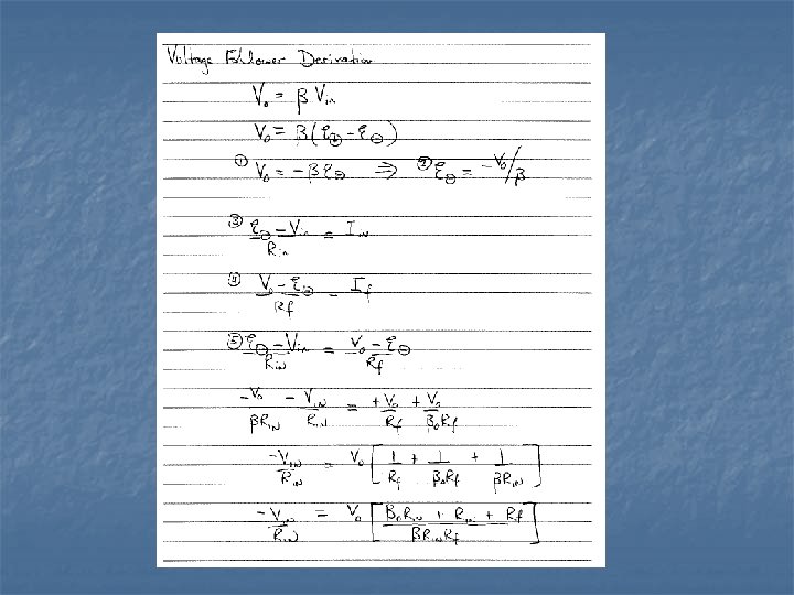
Voltage Follower Vin V 0 + Vo = V in Why would this be of any use ? Allows you to measure a voltage without drawing any current – almost completely eliminates loading errors.
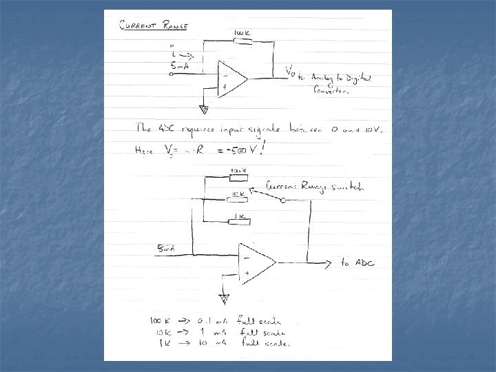
Current Amplifiers Rf Iin + Vo = - Iin Rf V 0
Summing Amplifiers Rf V 1 R 1 V 2 R 2 - V 3 R 3 + V 0
Integrating Amplifier C R Vi + V 0 And if you wanted to integrate currents ?
A Simple Galvanostat
A Simple Potentiostat
A Real Potentiostat
The design of electrochemical experiments n. Equilibrium techniques potentiometry, amperometry differential capacitance n. Steady state techniques voltammetry, polarography, coulometry and rotating electrodes n. Transient techniques chronoamperometry, chronocoulometry, chronopotentiometry In all experiments, precise control or measurements of potential, charge and/or current is an essential requirement of the experiment.
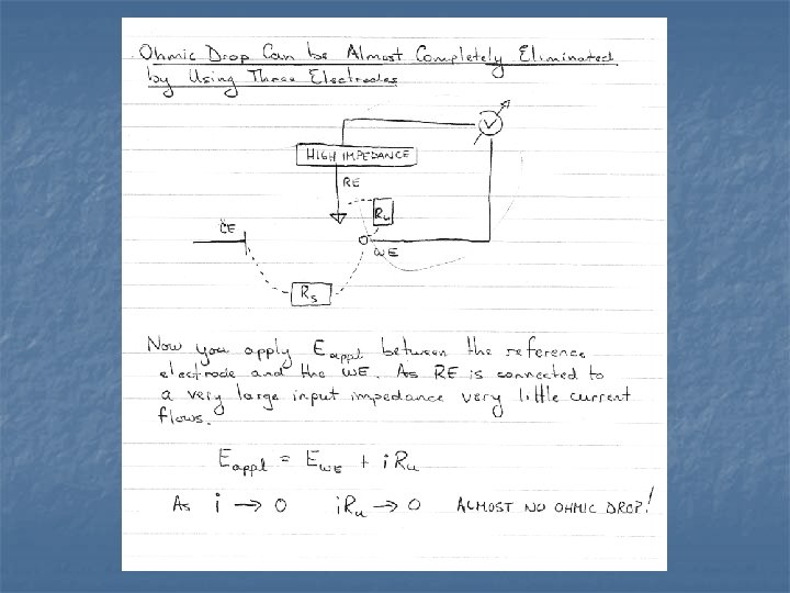
The design of electrochemical cell n Electrodes working electrode(s), counter electrode and reference electrode n n Electrolyte Cell container
Working electrode n n most common is a small sphere, small disc or a short wire, but it could also be metal foil, a single crystal of metal or semiconductor or evaporated thin film has to have useful working potential range can be large or small – usually < 0. 25 cm 2 smooth with well defined geometry for even current and potential distribution
Working electrode - examples n mercury and amalgam electrodes reproducible homogeneous surface, large hydrogen overvoltage. n wide range of solid materials – most common are “inert” solid electrodes like gold, platinum, glassy carbon. reproducible pretreatment procedure, proper mounting
Counter electrodes n n to supply the current required by the W. E. without limiting the measured response. current should flow readily without the need for a large overpotential. products of the C. E. reaction should not interfere with the reaction being studied. it should have a large area compared to the W. E. and should ensure equipotentiality of the W. E.
Reference electrode The role of the R. E. is to provide a fixed potential which does not vary during the experiment. A good R. E. should be able to maintain a constant potential even if a few microamps are passed through its surface.
Micropolarisation tests (a) response of a good and (b) bad reference electrode.
Reference electrodes - examples n mercury – mercurous chloride (calomel) the most popular R. E. in aq. solutions; usually made up in saturated KCl solution (SCE); may require separate compartment if chloride ions must be kept out of W. E. n silver – silver halide gives very stable potential; easy to prepare; may be used in non aqueous solutions
The electrolyte solution n n it consists of solvent and a high concentration of an ionised salt and electroactive species to increase the conductivity of the solution, to reduce the resistance between n n W. E. and C. E. (to help maintain a uniform current and potential distribution) and between W. E. and R. E. to minimize the potential error due to the uncompensated solution resistance i. Ru
Troubleshooting n n n is there any response? is the response incorrect or erratic? is the response basically correct but noisy?
For resistor as a dummy cell: W. E. C. E. + R. E.
For RC as a dummy cell (with some filtering in pot. ): W. E. C. E. + R. E.
For RC as a dummy cell (without any filtering in pot. ):