FUNCTIONS OF THE GOVERNING SYSTEM To contain the


 Signal")


- Slides: 19
FUNCTIONS OF THE GOVERNING SYSTEM Ø To contain the speed rise within acceptable limits if the unit gets disconnected from load. Ø To regulate the steam control valve position and hence load generated. Ø To control the initial run up and synchronization of the machine Ø To assist in matching the power generated to that demanded by responding to the network frequency changes.
SALENT FEATURES OF 200 MW KWU TURBINE GOVERNING SYSTEM Ø KWU 200 mw turbine is a throttle governed machine. Ø Two governors, electro-hydraulic and hydraulic are incorporated. Both the governors are connected in parallel. Ø Only one governor can be selected at a time through the process of hydraulic minimum selection. Ø The control valve opening depends on secondary oil pressure and there is a definite relationship between the opening of HP control valve and IP control valve. Ø Between 40 to 200 mw the turbine load is varied by changing the HP control valve throttling alone.
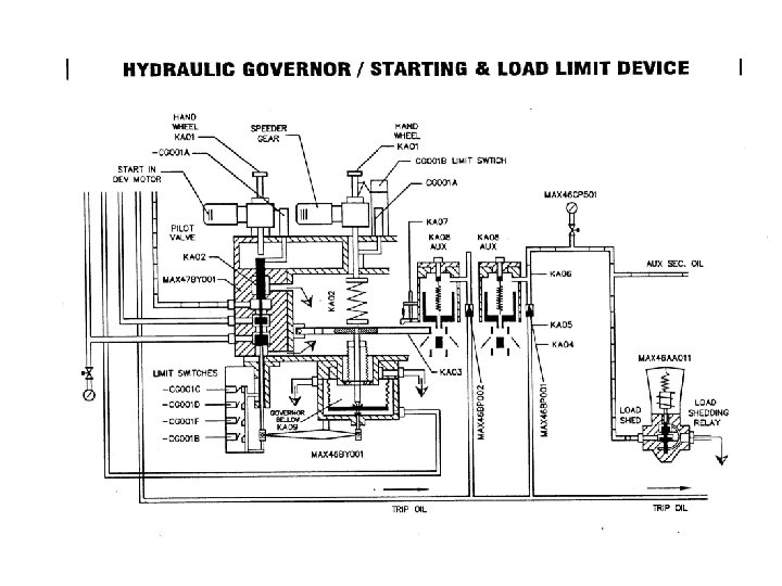
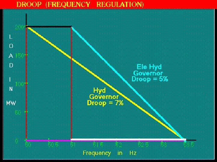
HYDRAULIC GOVERNOR SALENT FEATURES Ø Hydraulic governor is having only one control loop called speed controller. Ø HG consists of mechanical arrangement of spring and bellow. Ø Machine speed is measured and indicated as primary oil pressure. Ø Range of speed control is 2800 -3210 rpm. Ø Speed regulation range (droop) of HG is 7% and can not be changed while the machine is running. Ø HG acts as a back-up to the EHG. Ø HG can not be isolated mechanically like EHG and HG is considered to be the primary governor of the KWU turbine
ELECTRO-HYDRAULIC GOVERNOR SALENT FEATURES Ø EHG consists of three control loops for speed, load and pressure. Ø EHG optimizes the turbine life by conservative operation with the aid of TSE. Ø Faster response and precise frequency control. Ø Actual speed of the turbine is measured by using hall probes Ø Range of speed control is wider (0 -3210) rpm. Ø Speed regulation (Droop) can be changed from 2. 5% to 8% in a step of 0. 5% even when the machine runs on load. The usual setting of droop in EHG is 5%. Ø EHG can be mechanically isolated by closing the secondary oil line from the local.
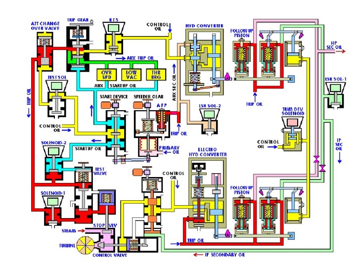
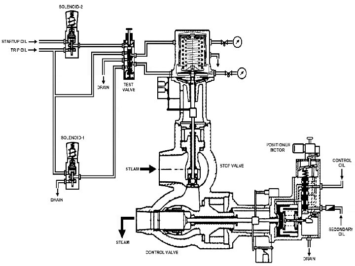
DIFFERENT OILS USED IN KWU TURBINE • • • Control oil (source oil) Signal oil (LP bypass operation) Auxiliary start-up oil Start-up oil Auxiliary trip oil Trip oil Auxiliary secondary oil Test oil Primary oil Lub oil Jacking oil
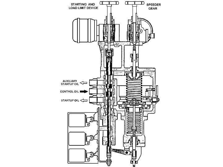
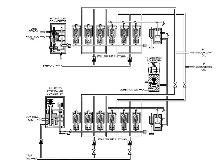
GOVERNING SYSTEM DEVICES • • • Remote trip solenoids Turbine trip gear (Main trip valve) Starting and load limiting device Speeder gear Auxiliary follow-up piston Follow-up piston Hydraulic amplifier Electro-hydraulic convertor Sequence trimming device Solenoid for load sheeding relay Extaction valve relay
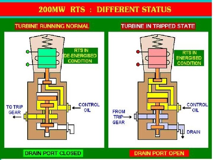
REMOTE TRIP SOLENOIDS
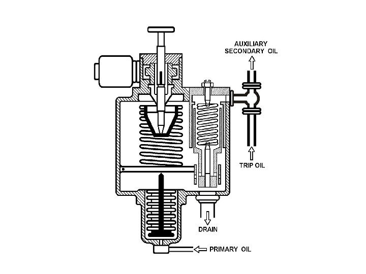
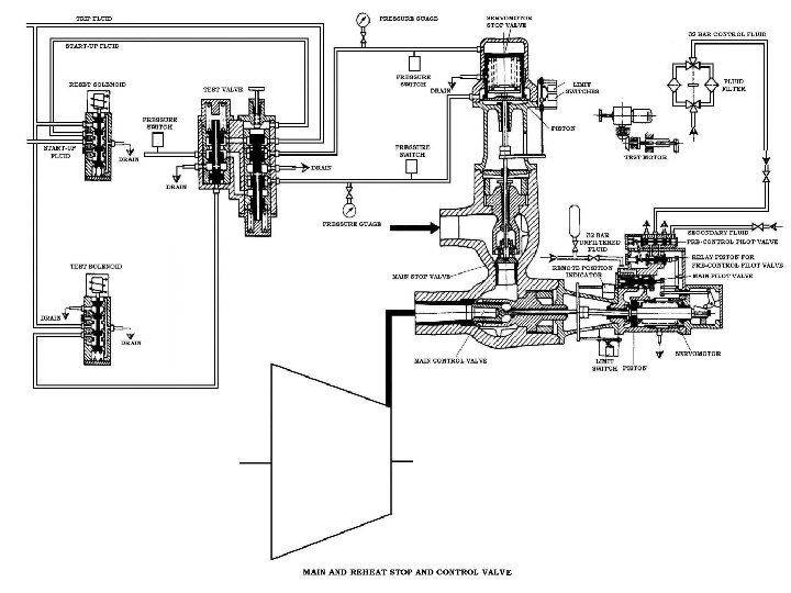
TURBINE TRIP GEAR
AUXILIARY TRIP FLUID DRAIN
DRAIN TRIP OIL CONTROL OIL AUXILIARY TRIP OIL AUXILIARY START-UP OIL MAIN TRIP VALVE