
Functional Verification of Hardware Designs n n EE
- Slides: 15
Functional Verification of Hardware Designs n n EE 764 – Functional Verification of Hardware Designs Course Objectives n n Learn to use verification tools and experiment on actual circuits designed in industry (or equal to) Learn to plan & carry out effective functional verification of a design Learn to work in teams to debug designs Both code and debug HDL design code Lecture 1 – Overview (r. Sp 06) © 2008 Joanne De. Groat, ECE, OSU -1 -
Functional Verification of Hardware Designs (cont) n By the end of the course the student will have n n n Verified several examples provided by the instructor (some may come from industry) Have an understanding of why verification is important Have an understanding of the level of complexity present in the verification of modern microcircuits Lecture 1 – Overview (r. Sp 06) © 2008 Joanne De. Groat, ECE, OSU -2 -
Syllabus/Grading/Project n n Syllabus Projects - Project 1 – Floating Point Adder Project 2 – Develop a package for injected error testing. - - - Students will work on projects 1, 2 in a group of two. Each is due 2 weeks from when assigned Project 3 – Fault tolerant circuit example which will include combinational and possibly sequential components. Project 4 – Floating Point Execution Sub Unit. - Students will work on projects 3 and 4 in a group of three. Each will be due three weeks from when assigned. Lecture 1 – Overview (r. Sp 06) © 2008 Joanne De. Groat, ECE, OSU -3 -
History 101 n VHDL 1 st standardized in 1987 by IEEE n n n VHDL about to be standardized again and will include many new aspects, several aimed specifically aimed toward verification (PSL) Verilog 1 st standardized in 1995 by IEEE Hardware Description Languages were the beginning of several new advances in chip and system design n Simulation of chips and systems Synthesis of digital hardware Verification Lecture 1 – Overview (r. Sp 06) © 2008 Joanne De. Groat, ECE, OSU -4 -
History continued n 1990 focus – Does chip work at all? n n 2000 focus – Does chip work in the system environment as specified? Today – more efficient verification than in 2000. Lecture 1 – Overview (r. Sp 06) © 2008 Joanne De. Groat, ECE, OSU -5 -
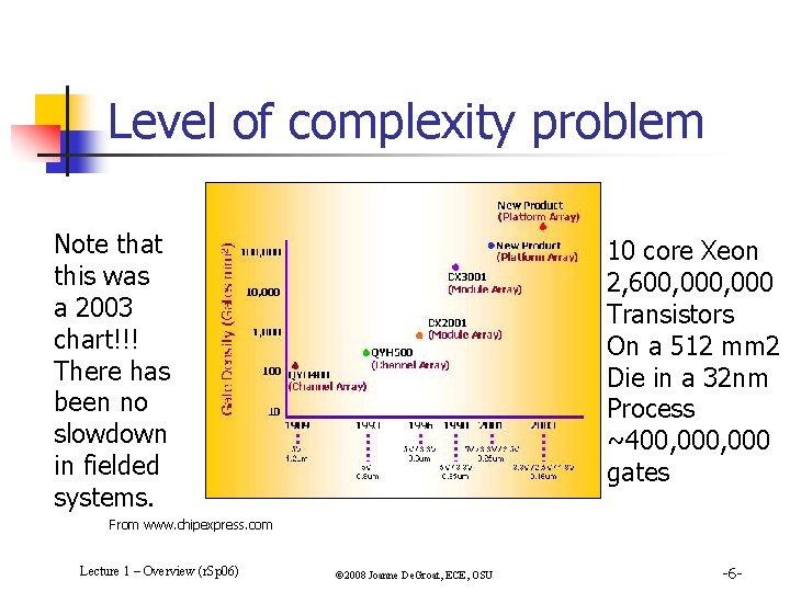
Level of complexity problem Note that this was a 2003 chart!!! There has been no slowdown in fielded systems. 10 core Xeon 2, 600, 000 Transistors On a 512 mm 2 Die in a 32 nm Process ~400, 000 gates From www. chipexpress. com Lecture 1 – Overview (r. Sp 06) © 2008 Joanne De. Groat, ECE, OSU -6 -
Today’s design issue n n Gate counts and system complexity growing exponentially Bulk of time in design of an new IC is spent on verification n n In most companies there is at least a 1 -to-1 ratio of design engineers to verification engineers. Real problem is not how to create the 12 million (or more) gate IC but how to verify it. Lecture 1 – Overview (r. Sp 06) © 2008 Joanne De. Groat, ECE, OSU -7 -
What is verification? n n n Verification is not a testbench or a series of testbenches. Verification is a process used to demonstrate the functional correctness of a design. It is the act of ensuring that the logic design conforms to the specifications. Verification does not insure that the specification is correct. (Next real advance in design will likely be specification languages! – Note new topics in text – Open Vera and e!) Lecture 1 – Overview (r. Sp 06) © 2008 Joanne De. Groat, ECE, OSU -8 -
Testbenches n n VHDL (and Verilog) testbenches refer to the code used to create an input sequence to the design under test (DUT) and optionally observe the response. In EE 762 the testbenches do both and the error signal indicates that the results do not equal what is expected. Lecture 1 – Overview (r. Sp 06) © 2008 Joanne De. Groat, ECE, OSU -9 -
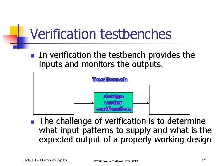
Verification testbenches n n In verification the testbench provides the inputs and monitors the outputs. The challenge of verification is to determine what input patterns to supply and what is the expected output of a properly working design Lecture 1 – Overview (r. Sp 06) © 2008 Joanne De. Groat, ECE, OSU -10 -
EE 762 testbenches n n The testbenches used in EE 762 check the essentials of basic correct operation and are less than a typical verification testbench. The goal of the EE 762 testbenches is to catch typical mistakes, check the operation in central and corner cases, and provide feedback to the student (the error signal). They are somewhat less than a testbench to be used for production of an IC. Lecture 1 – Overview (r. Sp 06) © 2008 Joanne De. Groat, ECE, OSU -11 -
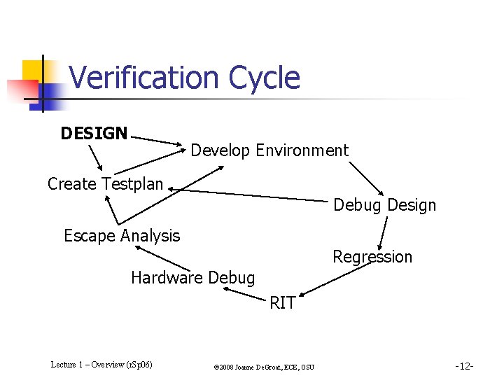
Verification Cycle DESIGN Develop Environment Create Testplan Debug Design Escape Analysis Regression Hardware Debug RIT Lecture 1 – Overview (r. Sp 06) © 2008 Joanne De. Groat, ECE, OSU -12 -
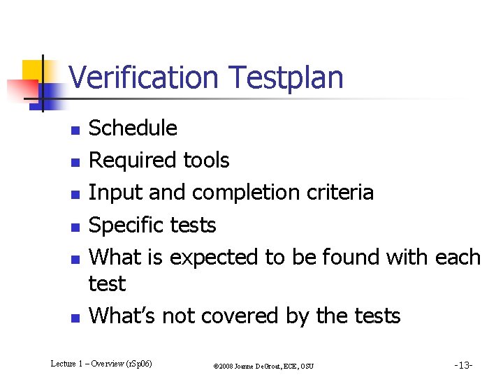
Verification Testplan n n n Schedule Required tools Input and completion criteria Specific tests What is expected to be found with each test What’s not covered by the tests Lecture 1 – Overview (r. Sp 06) © 2008 Joanne De. Groat, ECE, OSU -13 -
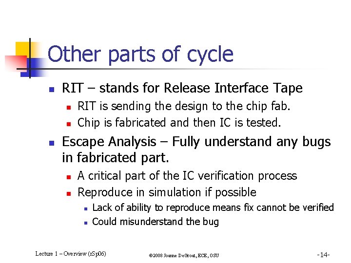
Other parts of cycle n RIT – stands for Release Interface Tape n n n RIT is sending the design to the chip fab. Chip is fabricated and then IC is tested. Escape Analysis – Fully understand any bugs in fabricated part. n n A critical part of the IC verification process Reproduce in simulation if possible n n Lack of ability to reproduce means fix cannot be verified Could misunderstand the bug Lecture 1 – Overview (r. Sp 06) © 2008 Joanne De. Groat, ECE, OSU -14 -
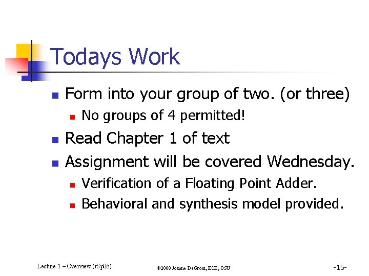
Todays Work n Form into your group of two. (or three) n n n No groups of 4 permitted! Read Chapter 1 of text Assignment will be covered Wednesday. n n Verification of a Floating Point Adder. Behavioral and synthesis model provided. Lecture 1 – Overview (r. Sp 06) © 2008 Joanne De. Groat, ECE, OSU -15 -