Functional Block of a Computer Block diagram of

Functional Block of a Computer

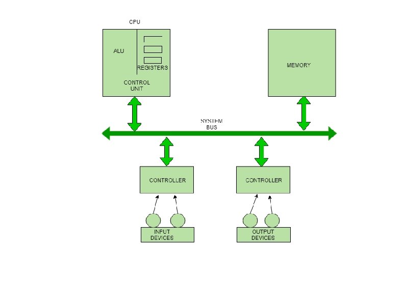
Block diagram of a computer gives you the pictorial representation of a computer that how computer works from feeding the data/problem to getting the result.
, Input/Output")
Computer system consists of three parts, that are central processing unit (CPU), Input/Output Devices and Memory. The Central Processing Unit (CPU) is divided into two parts again: arithmetic logic unit (ALU) and the control unit (CU). The input devices takes the input, the central processing unit does the processing of data and the output devices produces the output. The memory unit holds the data and instructions during the processing.

Input Devices Input devices take input and convert it into binary language that the computer understands. The information fed through the input unit is stored in computer's memory for processing and the final result stored in memory can be recorded or display on the output medium. Example - keyboard, mouse, joystick, scanner etc.
 Brain of the computer system. All major calculation and comparisons")
Central Processing Unit (CPU) Brain of the computer system. All major calculation and comparisons are made inside the CPU. Process all the Instruction which is given to computer. Responsible for activation and controlling the operation of other unit.

CPU Continue. . It first fetches instructions from memory/Input device and then interprets them so as to know what is to be done. Thereafter CPU executes or performs the required computation and then either stores the output in memory or displays on the output device. The CPU has three main components which are responsible for different functions – 1. Arithmetic Logic Unit (ALU) 2. Control Unit (CU) 3. Memory registers
 performs all arithmetic operations such as addition,")
CPU Continue. . Arithmetic Logic Unit (ALU) performs all arithmetic operations such as addition, subtraction, multiplication and division. It also uses logic operation for comparison.
 of a CPU controls the entire operation of")
CPU Continue. . Control Unit (CU) of a CPU controls the entire operation of the computer. It also controls all devices such as memory, input/output devices connected to the CPU. Control Unit fetches instructions from memory, decodes the instruction, interprets the instruction to know what the task are to be performed and executes the instruction.

CPU Continue. . Memory Registers A register is a temporary unit of memory in the CPU. Register store the data which is directly used by the CPU. Registers can be of different sizes(16 bit, 32 bit, 64 bit and so on) Each register in CPU has a specific function like storing data, storing an instruction, storing address of a location in memory etc. Accumulator is the main register in the ALU and contains one of the operands of an operation to be performed in the ALU.

Memory Memory attached to the CPU is used for storage of data and instructions and is called internal memory. The internal memory is divided into many storage locations, each of which can store data or instructions. Each memory location is of the same size and has an address. With the help of the address, the computer can read any memory location easily without having to search the entire memory.

Memory Continue. . When a program is executed, it’s data is copied to the internal memory and is stored in the memory till the end of the execution. The internal memory is also called the Primary memory or Main memory.

Memory Continue. . Internal Memory 1. RAM – Static RAM, Dynamic RAM 2. ROM – PROM, EEPROM External Memory or Auxillary Memory or Secondary Memory, example – Magnetic disk, Magnetic tape, Pen Drive etc Cache Memory Note – Refer memory hierarchy of module 4 for detail.

Output Devices The output devices produce or generate the desired result according to our input. The computer system is linked or connected to the outside world with the help of output devices. features: 1. These devices receive or accept the data in the binary form. 2. The output devices convert the binary code into the human-readable form. 3. These devices produce the converted result and show to the user.
- Slides: 14