FULL WAVE RECTIFIER DR A ANBARASI ASSOCIATE PROFESSOR

FULL WAVE RECTIFIER DR. A. ANBARASI ASSOCIATE PROFESSOR DEPARTMENT OF PHYSICS CUDDALORE

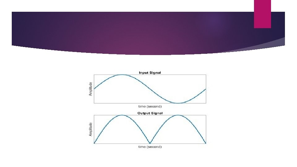
Full wave rectifier

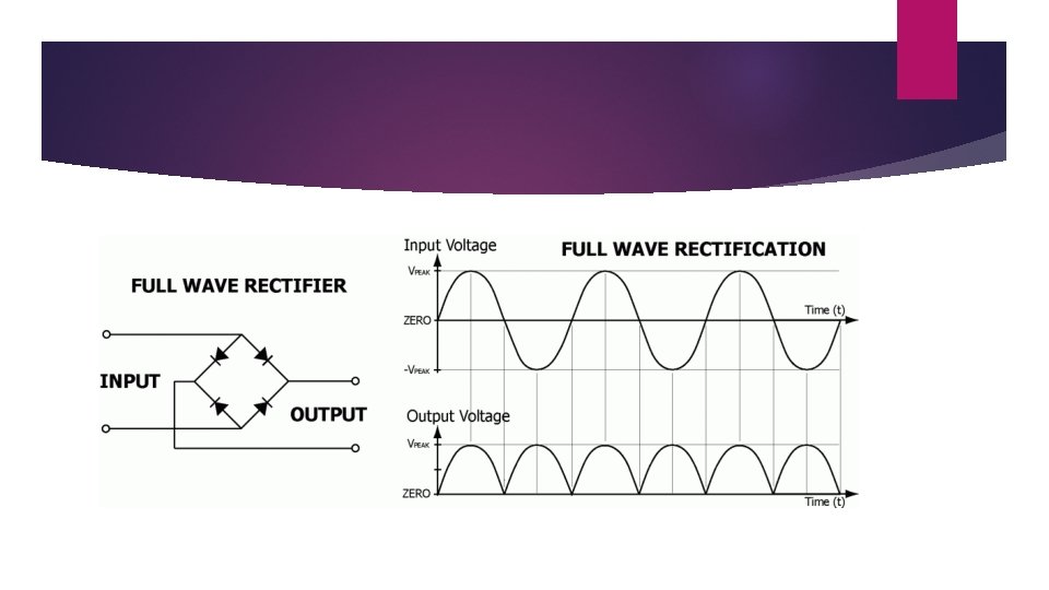
Full wave rectifier The full wave rectifier circuit consists of two power diodes connected to a single load resistance (RL) with each diode taking it in turn to supply current to the load resistor. When point A of the transformer is positive with respect to point A, diode D 1 conducts in the forward direction as indicated by the arrows. When point B is positive in the negative half of the cycle with respect to C point, the diode D 2 conducts in the forward direction and the current flowing through resistor R is in the same direction for both half-cycles of the wave.

Working of full wave rectifier The four diodes labelled D 1 to D 4 are arranged in series pairs with only two diodes conducting current during each half cycle duration. When the positive half cycle of the supply goes, D 1, D 2 diodes conduct in a series while diodes D 3 and D 4 are reverse biased and the current flows through the load. During the negative half cycle, D 3 and D 4 diodes conduct in a series and diodes D 1 and D 2 switch off as they are now reverse biased configuration.

Working of full wave rectifier Given Circuit gives a overview on working of full wave rectifier. A circuit that produces the same output waveform as the full wave rectifier circuit a is that of the Full Wave Bridge Rectifier. Single phase rectifier uses four individual rectifying diodes connected in a closed loop bridge configuration to produce the desired output wave. The advantage of this bridge circuit is that it does not require a special center tapped transformer, so it reduces its size and cost. Single secondary winding is connected to one side of the diode bridge network and the load to the other side.

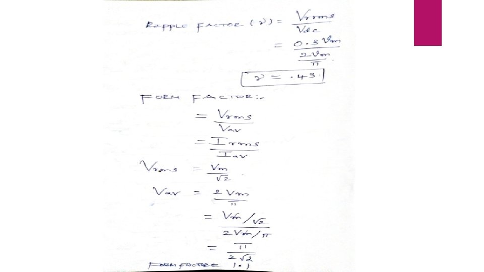
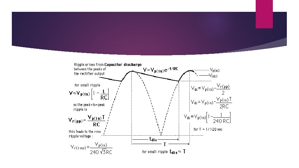
RIPPLE FACTOR the rectifier output mainly includes the AC component as well as the DC component. The ripple can be defined as the AC component within the resolved output. The A. C component within the output is unwanted as well as estimates the pulsations within the output of the rectifier. Here the ripple voltage is nothing but the AC component within o/p of the rectifier. Similarly, the ripple current is an AC component within o/p current.

The RMS value and the DC component and RMS value within the output of the rectifier. The symbol is denoted with gamma

Ripple factor derivation Derivation According to the definition of R. F, the whole load current RMS value can be given by IRMS = √I 2 dc + I 2 ac (or) Iac = √I 2 rms + I 2 dc When the above equation is divided by using Idc then we can get the following equation.
 of Centre Tap Full Wave Rectifier: PIV")
FULL WAVE RECTIFIER Peak Inverse Voltage (PIV) of Centre Tap Full Wave Rectifier: PIV is defined as the maximum possible voltage across a diode during its reverse bias. During the first half that is positive half of the input, the diode D 1 is forward bias and thus conducts providing no resistance at all. Thus, the total voltage Vs appears in the upper-half of the ac supply, provided to the load resistance R. Similarly, in the case of diode D 2 for the lower half of the transformer total secondary voltage developed appears at the load. The amount of voltage that drops across the two diodes in reverse bias is given as PIV of D 2 = Vm + Vm = 2 Vm PIV of D 1 = 2 Vm Vm is the voltage developed across upper and lower halves.

Peak current The peak current is the instantaneous value of the voltage applied to the rectifier. It can be written as Vs = Vsm Sinwt Let us assume that the diode has a forward resistance of RF ohms and a reverse resistance is equal to infinity, thus current flowing through the load resistance RL is given as Im = Vsm / (RF + RL)

Output current Since the current is same through the load resistance RL in the two halves of the ac cycle, magnitude of dc current Idc, which is equal to the average value of ac current, can be obtained by integrating the current i 1 between 0 and pi or current i 2 between pi and 2 pi.

“ FULL WAVE RECTIFIER DERIVATION ”


FULL WAVE RECTIFIER

During positive half cycle

Negative half cycle

- Slides: 24