
Full Duplex Low Power Systems for High Throughput
- Slides: 41
Full Duplex, Low Power Systems, for High Throughput Communication and Computing Platforms Ahmed M. Eltawil Wireless Systems and Circuits Laboratory University of California, Irvine
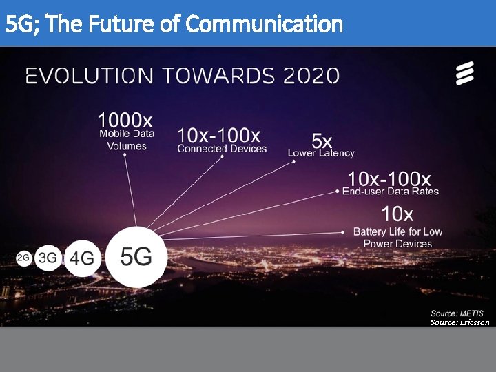
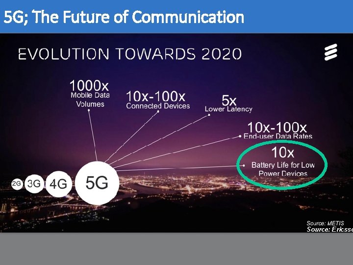
5 G; The Future of Communication Source: Ericsson
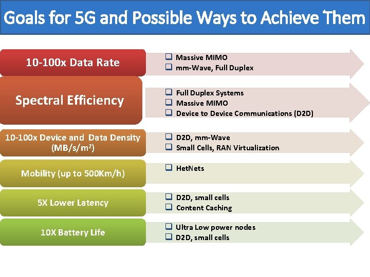
Goals for 5 G and Possible Ways to Achieve Them 10 -100 x Data Rate Spectral Efficiency 10 -100 x Device and Data Density (MB/s/m 2) Mobility (up to 500 Km/h) 5 X Lower Latency 10 X Battery Life q Massive MIMO q mm-Wave, Full Duplex q Full Duplex Systems q Massive MIMO q Device to Device Communications (D 2 D) q D 2 D, mm-Wave q Small Cells, RAN Virtualization q Het. Nets q D 2 D, small cells q Content Caching q Ultra Low power nodes q D 2 D, small cells
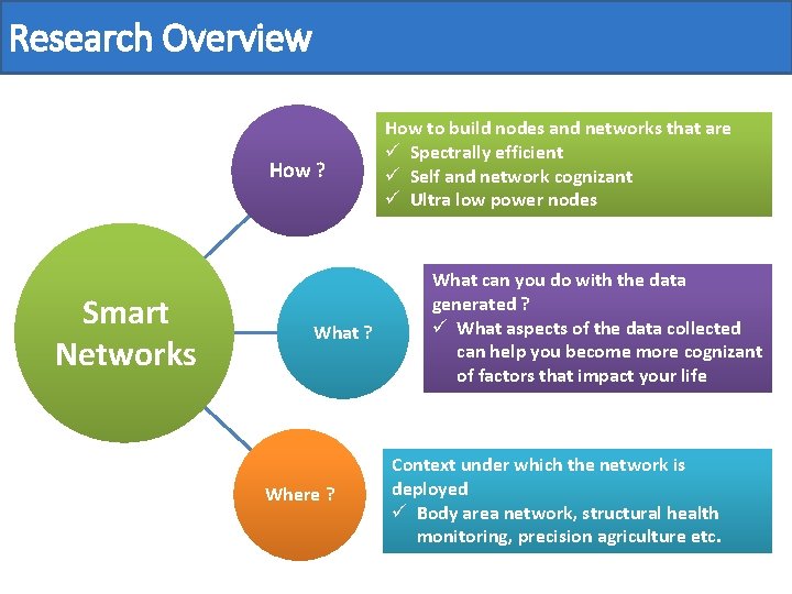
Research Overview How ? Smart Networks What ? Where ? How to build nodes and networks that are ü Spectrally efficient ü Self and network cognizant ü Ultra low power nodes What can you do with the data generated ? ü What aspects of the data collected can help you become more cognizant of factors that impact your life Context under which the network is deployed Ericsson ü Body area network, structural. Source: health monitoring, precision agriculture etc.
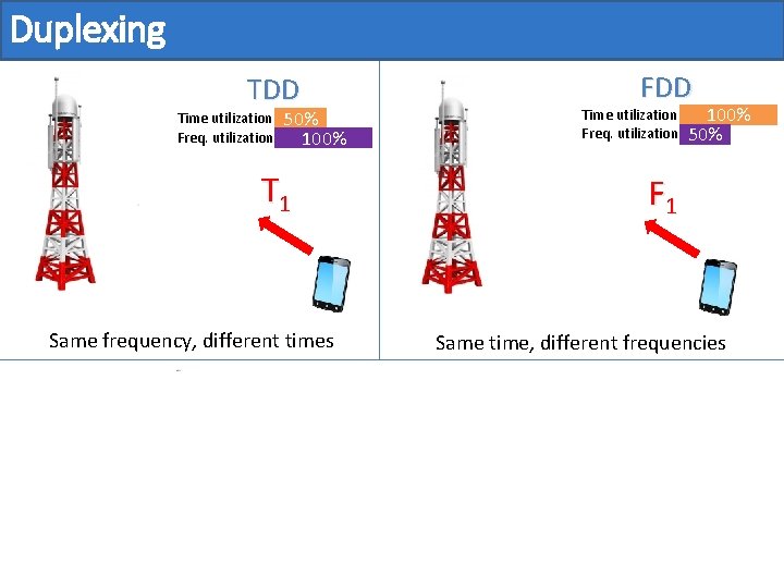
Duplexing FDD Time utilization Freq. utilization T 2 Time utilization Freq. utilization 50% 100% F 2 T 1 Same frequency, different times 100% 50% F 1 Same time, different frequencies Full Duplex Time utilization Freq. utilization Same time, same frequency 100%
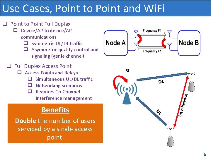
Use Cases, Point to Point and Wi. Fi q Point to Point Full Duplex q Device/AP to device/AP communications q Symmetric UL/DL traffic q Asymmetric quality control and signaling (genie channel) Double the number of users serviced by a single access point. ce DL UL Benefits SI feren q Access Points and Relays q Simultaneous UL/DL traffic q Networking scenarios q Requires Co-Channel Interference management Inter q Full Duplex Access Point 6
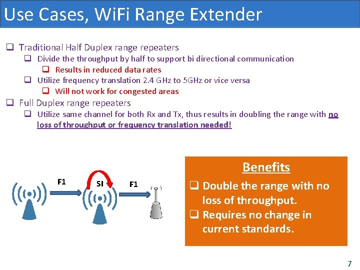
Use Cases, Wi. Fi Range Extender q Traditional Half Duplex range repeaters q Divide throughput by half to support bi directional communication q Results in reduced data rates q Utilize frequency translation 2. 4 GHz to 5 GHz or vice versa q Will not work for congested areas q Full Duplex range repeaters q Utilize same channel for both Rx and Tx, thus results in doubling the range with no loss of throughput or frequency translation needed! Benefits F 1 SI F 1 q Double the range with no loss of throughput. q Requires no change in current standards. 7
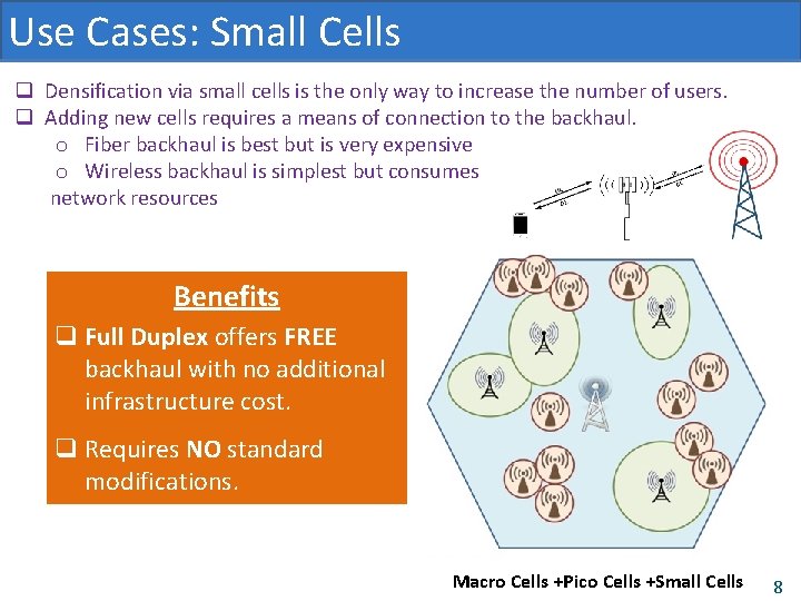
Use Cases: Small Cells q Densification via small cells is the only way to increase the number of users. q Adding new cells requires a means of connection to the backhaul. o Fiber backhaul is best but is very expensive o Wireless backhaul is simplest but consumes network resources Benefits q Full Duplex offers FREE backhaul with no additional infrastructure cost. q Requires NO standard modifications. Macro Cells. Macro +Pico Cells +Small Cells Macro Cells 8
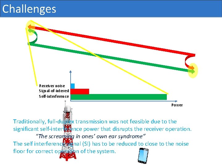
Challenges Receiver noise Signal-of-interest Self-interference Power Traditionally, full-duplex transmission was not feasible due to the significant self-interference power that disrupts the receiver operation. “The screaming in ones’ own ear syndrome” The self interference signal (SI) has to be reduced to close to the noise floor for correct operation of the system.
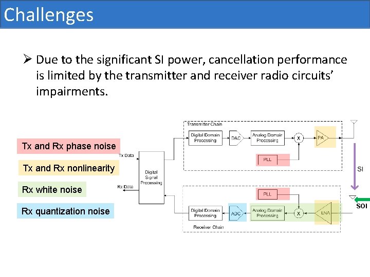
Challenges Ø Due to the significant SI power, cancellation performance is limited by the transmitter and receiver radio circuits’ impairments. Tx and Rx phase noise Tx and Rx nonlinearity Rx white noise Rx quantization noise SOI
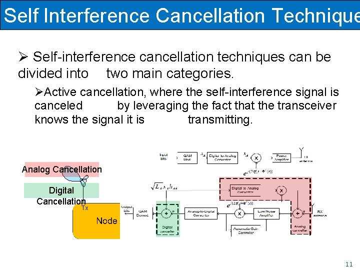
Self Interference Cancellation Technique Ø Self-interference cancellation techniques can be divided into two main categories. ØActive Passive cancellation, suppression, where thethe self-interference signal is is canceled suppressed by leveraging in thethe propagation fact that the domain. transceiver knows the signal it is transmitting. Analog Cancellation Digital Cancellation Tx Rx 11
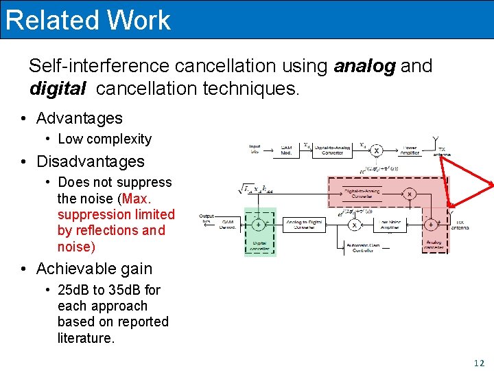
Related Work Self-interference cancellation using analog and digital cancellation techniques. • Advantages • Low complexity • Disadvantages • Does not suppress the noise (Max. suppression limited by reflections and noise) • Achievable gain • 25 d. B to 35 d. B for each approach based on reported literature. 12
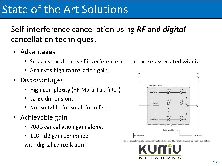
State of the Art. Related Solutions Work Self-interference cancellation using RF and digital cancellation techniques. • Advantages • Suppress both the self interference and the noise associated with it. • Achieves high cancellation gain. • Disadvantages • High complexity (RF Multi-Tap filter) • Large dimensions • Not suitable for small form factor • Achievable gain • 70 d. B cancellation gain alone. • 110+ d. B gain combined with digital cancellation 13
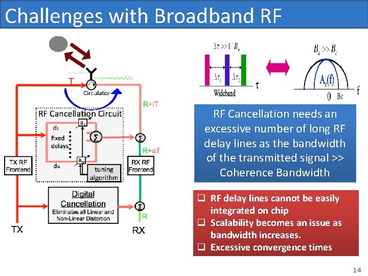
Challenges with Broadband RF Cancellation needs an excessive number of long RF delay lines as the bandwidth of the transmitted signal >> Coherence Bandwidth q RF delay lines cannot be easily integrated on chip q Scalability becomes an issue as bandwidth increases. q Excessive convergence times 14
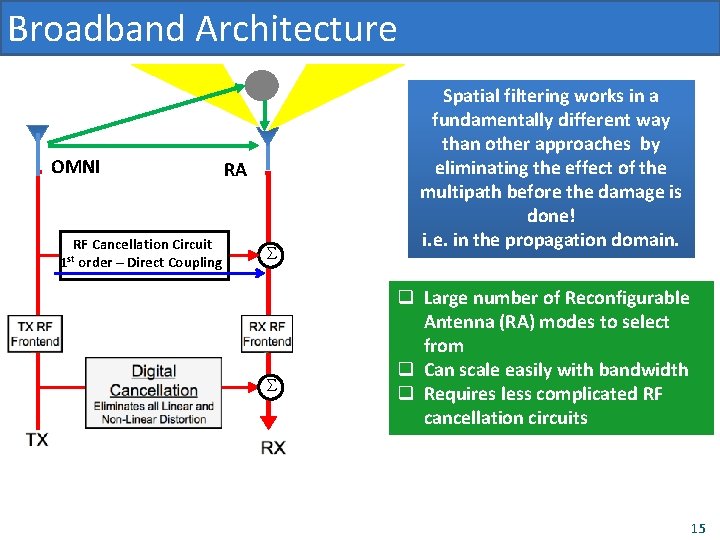
Broadband Architecture OMNI RF Cancellation Circuit order – Direct Coupling 1 st RA S S Spatial filtering works in a fundamentally different way than other approaches by eliminating the effect of the multipath before the damage is done! i. e. in the propagation domain. q Large number of Reconfigurable Antenna (RA) modes to select from q Can scale easily with bandwidth q Requires less complicated RF cancellation circuits 15
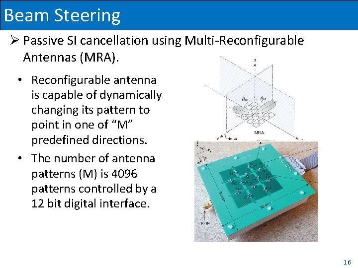
Beam Steering Ø Passive SI cancellation using Multi-Reconfigurable Antennas (MRA). • Reconfigurable antenna is capable of dynamically changing its pattern to point in one of “M” predefined directions. • The number of antenna patterns (M) is 4096 patterns controlled by a 12 bit digital interface. 16
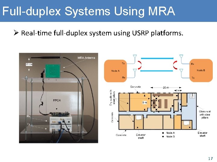
Full-duplex Systems Using MRA Ø Real-time full-duplex system using USRP platforms. 17
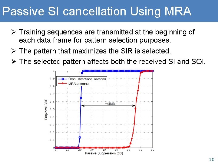
Passive SI cancellation Using MRA Ø Training sequences are transmitted at the beginning of each data frame for pattern selection purposes. Ø The pattern that maximizes the SIR is selected. Ø The selected pattern affects both the received SI and SOI. 18
Passive SI cancellation Using MRA Ø The main issue is the training overhead. Ø Reducing the training overhead requires Ø Reducing the number of patterns to be trained. Ø Reducing the training periodicity. Ø How does this affect the cancellation performance? 19
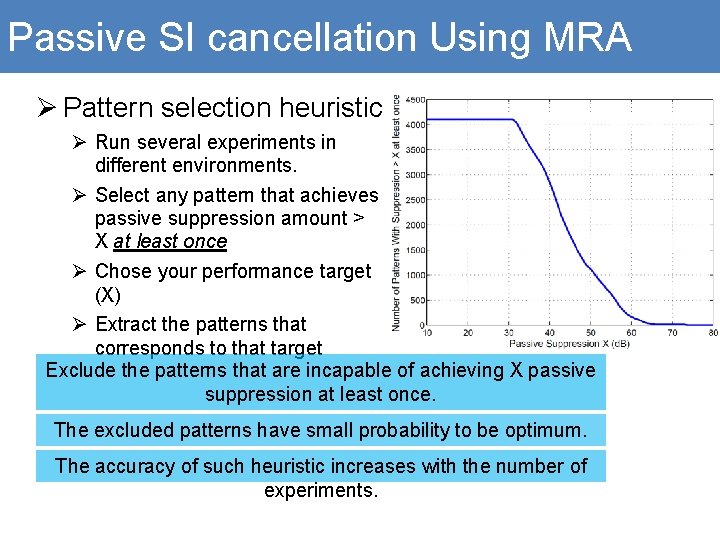
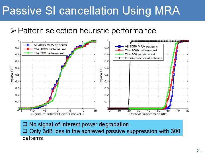
Passive SI cancellation Using MRA Ø Pattern selection heuristic Ø Run several experiments in different environments. Ø Select any pattern that achieves passive suppression amount > X at least once Ø Chose your performance target (X) Ø Extract the patterns that corresponds to that target Exclude the patterns that are incapable of achieving X passive suppression at least once. The excluded patterns have small probability to be optimum. The accuracy of such heuristic increases with the number of experiments.
Passive SI cancellation Using MRA Ø Pattern selection heuristic performance q No signal-of-interest power degradation. q Only 3 d. B loss in the achieved passive suppression with 300 patterns. 21
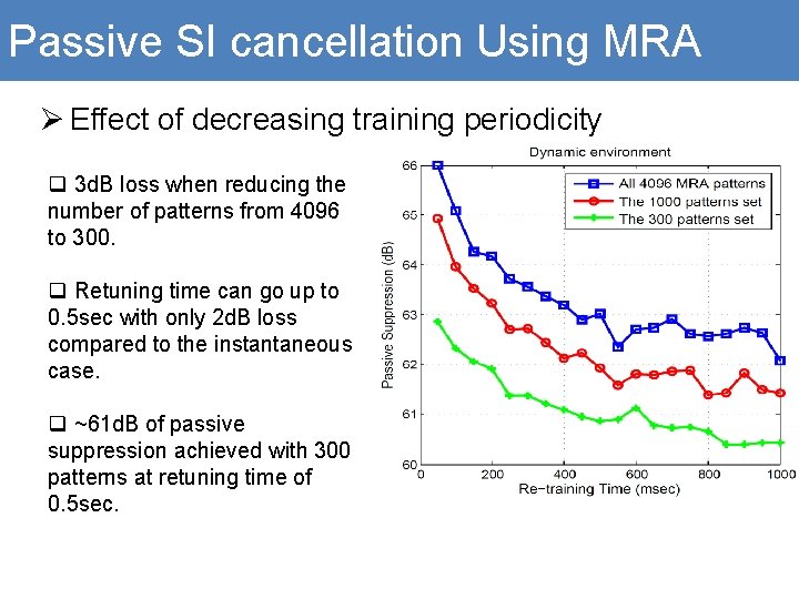
Passive SI cancellation Using MRA Ø Effect of decreasing training periodicity q 3 d. B loss when reducing the number of patterns from 4096 to 300. q Retuning time can go up to 0. 5 sec with only 2 d. B loss compared to the instantaneous case. q ~61 d. B of passive suppression achieved with 300 patterns at retuning time of 0. 5 sec.
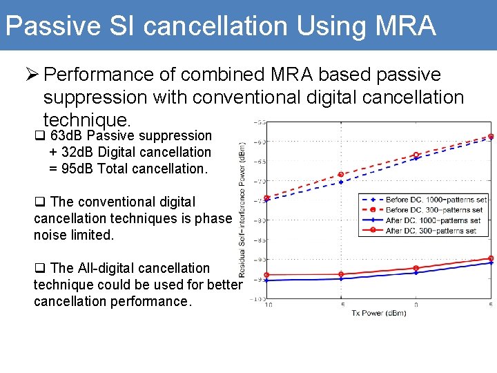
Passive SI cancellation Using MRA Ø Performance of combined MRA based passive suppression with conventional digital cancellation technique. q 63 d. B Passive suppression + 32 d. B Digital cancellation = 95 d. B Total cancellation. q The conventional digital cancellation techniques is phase noise limited. q The All-digital cancellation technique could be used for better cancellation performance.
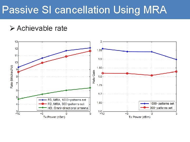
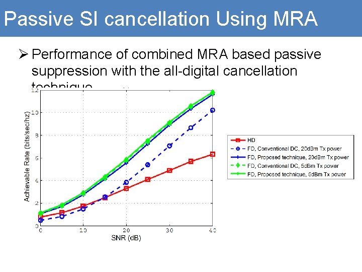
Passive SI cancellation Using MRA Ø Achievable rate
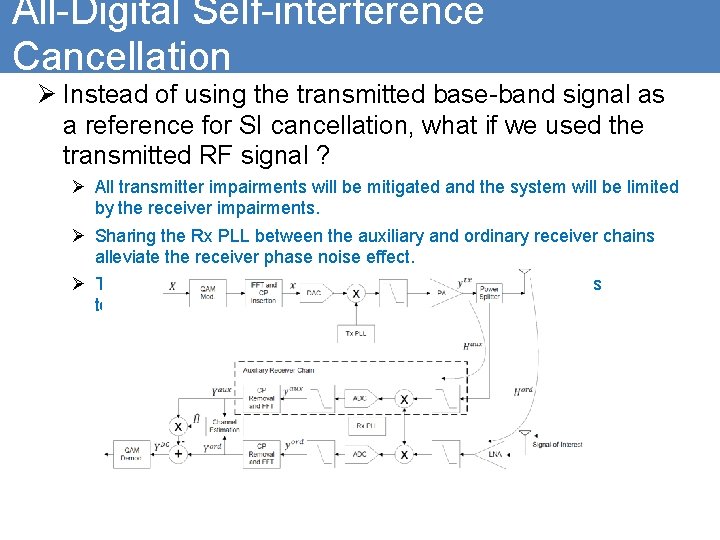
All-Digital Self-interference Cancellation Ø Instead of using the transmitted base-band signal as a reference for SI cancellation, what if we used the transmitted RF signal ? Ø All transmitter impairments will be mitigated and the system will be limited by the receiver impairments. Ø Sharing the Rx PLL between the auxiliary and ordinary receiver chains alleviate the receiver phase noise effect. Ø The receiver nonlinearity could be eliminated using the previous technique.
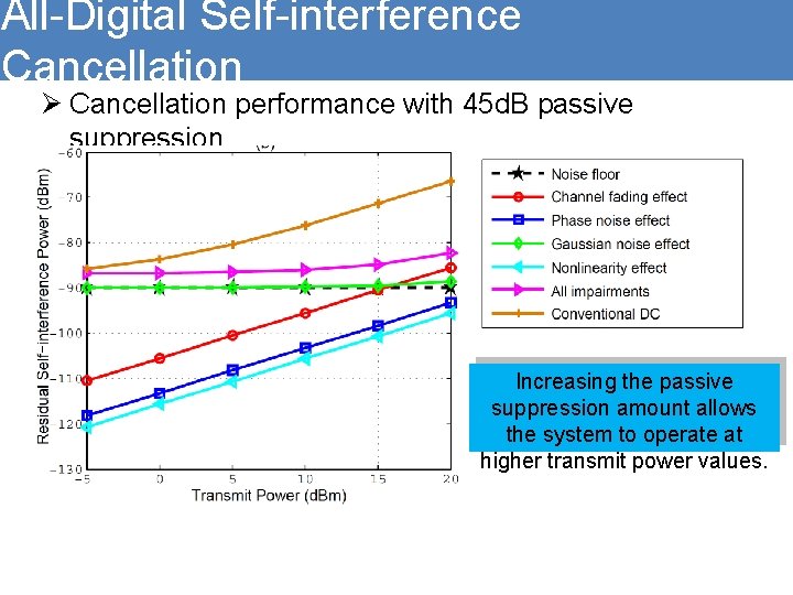
All-Digital Self-interference Cancellation Ø Cancellation performance with 45 d. B passive suppression Increasing the passive suppression amount allows the system to operate at higher transmit power values.
Passive SI cancellation Using MRA Ø Performance of combined MRA based passive suppression with the all-digital cancellation technique.
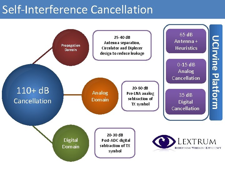
Self-Interference Cancellation 65 d. B Antenna + Heuristics 0 -15 d. B Analog Cancellation 110+ d. B Analog Domain Cancellation Digital Domain 20 -60 d. B Pre-LNA analog subtraction of TX symbol 20 -30 d. B Post-ADC digital subtraction of TX symbol 35 d. B Digital Cancellation UCIrvine Platform Propagation Domain 25 -40 d. B Antenna separation, Circulator and Diplexer design to reduce leakage
5 G; The Future of Communication Source: Ericsso
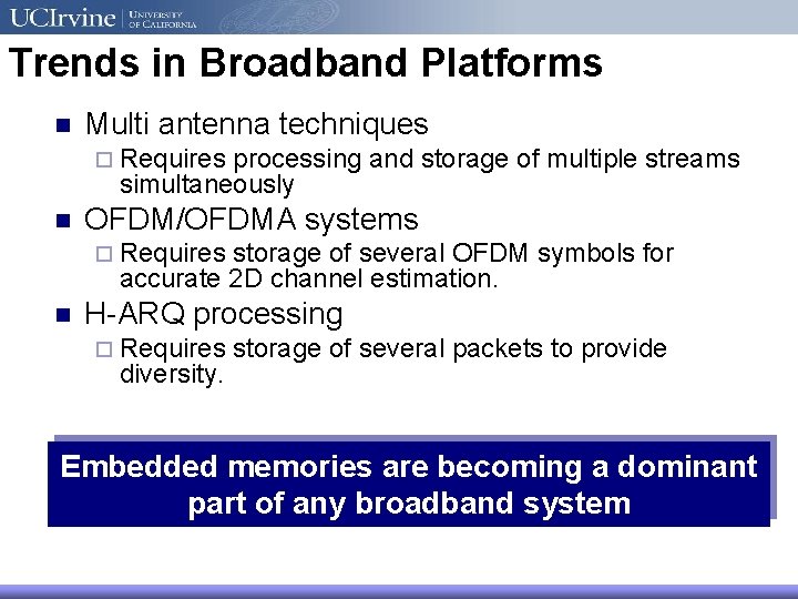
Trends in Broadband Platforms n Multi antenna techniques ¨ Requires processing and storage of multiple streams simultaneously n OFDM/OFDMA systems ¨ Requires storage of several OFDM symbols for accurate 2 D channel estimation. n H-ARQ processing ¨ Requires diversity. storage of several packets to provide Embedded memories are becoming a dominant part of any broadband system
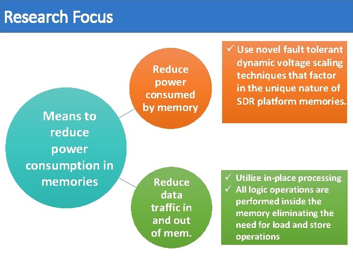
Research Focus Means to reduce power consumption in memories Reduce power consumed by memory Reduce data traffic in and out of mem. ü Use novel fault tolerant dynamic voltage scaling techniques that factor in the unique nature of SDR platform memories. ü Utilize in-place processing ü All logic operations are performed inside the memory eliminating the need for load. Source: and Ericsson store operations
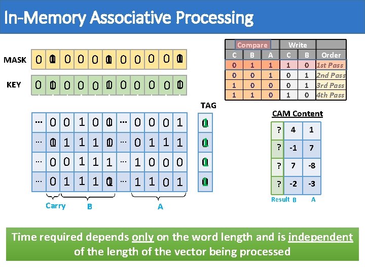
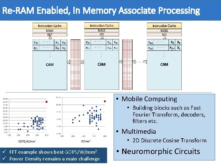
In-Memory Associative Processing MASK 0 10 0 0 0 0 10 KEY 0 10 0 0 0 0 10 TAG. . . 0 0 1 1 Carry B 0 01 . . . 1 10 1 1 1 01 . . 0 0 0 1 1 1 1 0 0 0 1 1 0 1 A 01 01 01 0 1 Compare C B A 0 1 1 0 Write C B 1 0 0 1 1 0 Order 1 st Pass 2 nd Pass 3 rd Pass 4 th Pass CAM Content 4 1 ? -1 7 7 -8 ? -2 -3 Result B A ? ? Time required depends only on the word length and is independent of the length of the vector being processed
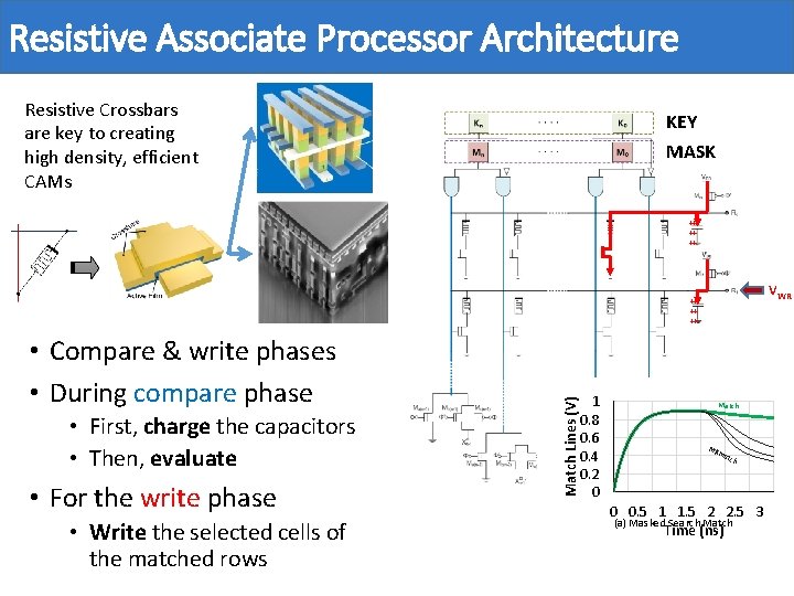
Resistive Associate Processor Architecture Resistive Crossbars are key to creating high density, efficient CAMs KEY MASK ++ ++ ++ VWR • Compare & write phases • During compare phase • First, charge the capacitors • Then, evaluate • For the write phase • Write the selected cells of the matched rows Match Lines (V) ++ ++ ++ 1 0. 8 0. 6 0. 4 0. 2 0 Match Mis ma tch 0 0. 5 1 1. 5 2 2. 5 3 (a) Masked Search Match Time (ns)
Re-RAM Enabled, In Memory Associate Processing • Mobile Computing • Building blocks such as Fast Fourier Transform, decoders, filters etc. • Multimedia • 2 D Discrete Cosine Transform ü FFT example shows best GOPS/W/mm 2 ü Power Density remains a main challenge • Neuromorphic Circuits
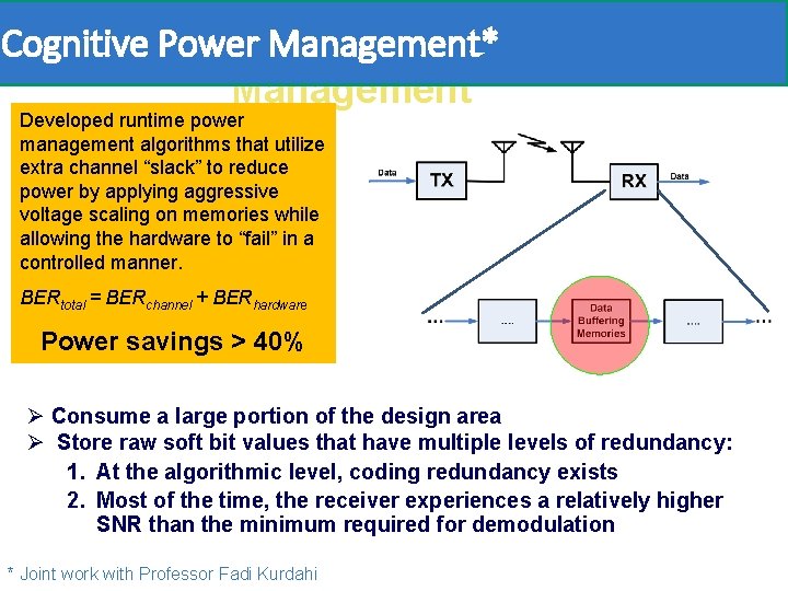
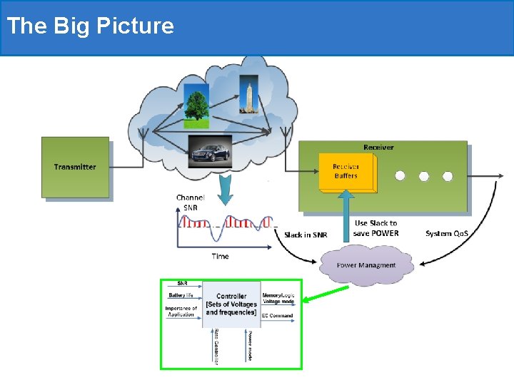
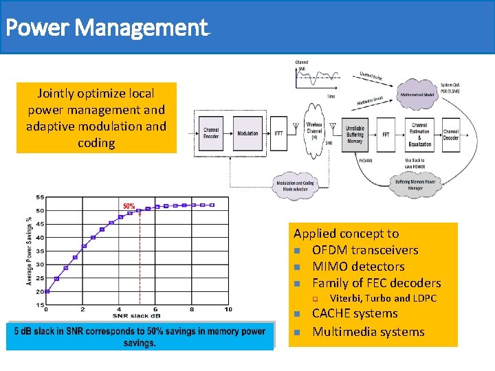
P 1 -Cognitive Power Management*Power Management Developed runtime power management algorithms that utilize extra channel “slack” to reduce power by applying aggressive voltage scaling on memories while allowing the hardware to “fail” in a controlled manner. BERtotal = BERchannel + BERhardware Power savings > 40% Ø Consume a large portion of the design area Ø Store raw soft bit values that have multiple levels of redundancy: 1. At the algorithmic level, coding redundancy exists 2. Most of the time, the receiver experiences a relatively higher SNR than the minimum required for demodulation * Joint work with Professor Fadi Kurdahi
The Big Picture
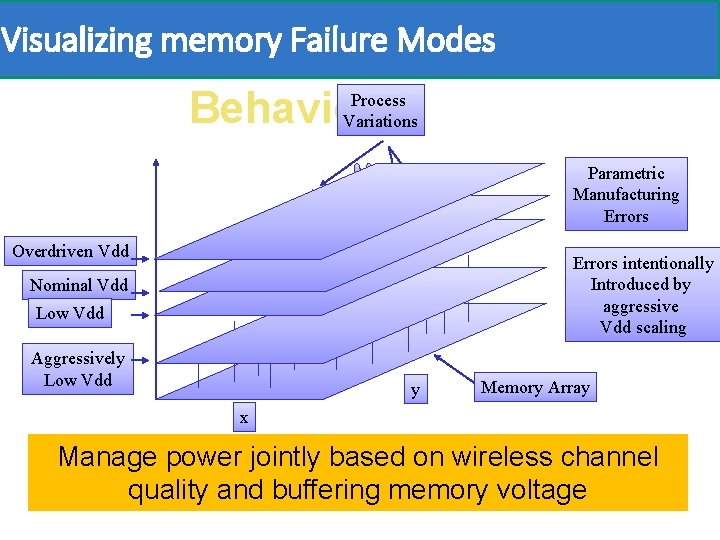
Visualizing memory Failure Modes Visualizing Memory Process Behavior Variations Parametric Manufacturing Errors Overdriven Vdd Errors intentionally Introduced by aggressive Vdd scaling Nominal Vdd Low Vdd Aggressively Low Vdd y Memory Array x Manage power jointly based on wireless channel quality and buffering memory voltage
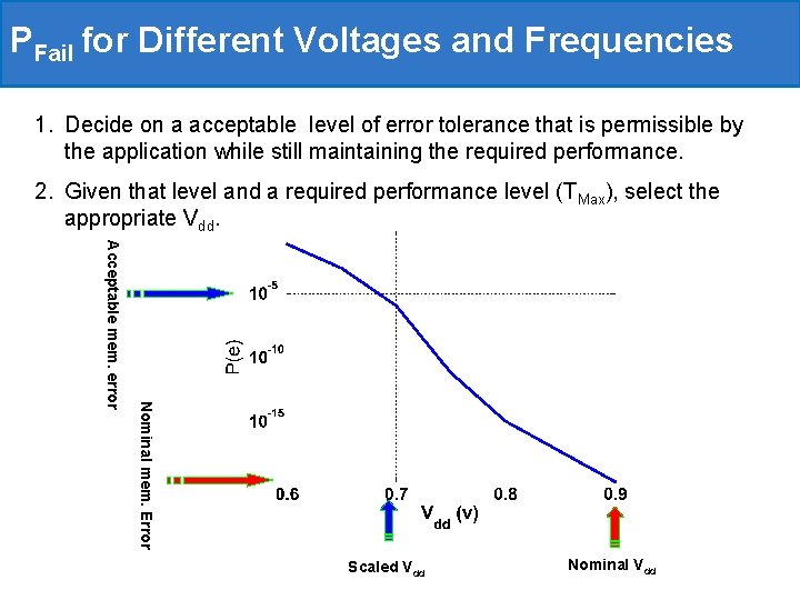
PFail for Different Voltages and Frequencies 1. Decide on a acceptable level of error tolerance that is permissible by the application while still maintaining the required performance. 2. Given that level and a required performance level (TMax), select the appropriate Vdd. Nominal mem. Error Acceptable mem. error Scaled Vdd Nominal Vdd
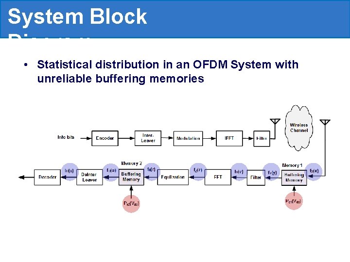
System Block Diagram • Statistical distribution in an OFDM System with unreliable buffering memories
Power Management Jointly optimize local power management and adaptive modulation and coding Applied concept to n OFDM transceivers n MIMO detectors n Family of FEC decoders q n n Viterbi, Turbo and LDPC CACHE systems Multimedia systems
Thank You Ahmed M. Eltawil aeltawil@uci. edu +1 (949) 824 -0125 http: //newport. eecs. uci. edu/~aeltawil/