Fuel Cells OBJECTIVE Able to know and acknowledge

Fuel Cells OBJECTIVE: Able to know and acknowledge the different types of fuel cells and its problems for sustainable development OUTCOME: At the end of this session one can able to Identify the different types of fuel cell performance parameters, efficiency levels and solve the variety of numerical problems connected in different ranges

CONTENTS 1. TYPES OF FUEL CELLS 2. PROBLEMS ON FUEL CELLS 3. CASE STUDIES ON FUEL CELLS 4. PERFORMANCE ANALYSIS OF FUEL CELLS 5. FUEL CELL OPTIMIZATION
 2. DIRECT METHANOL FUEL CELL (DMFC)")
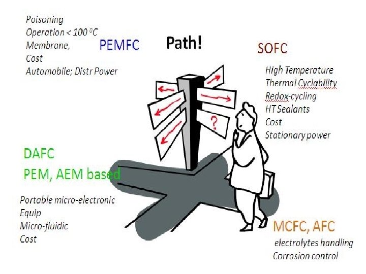
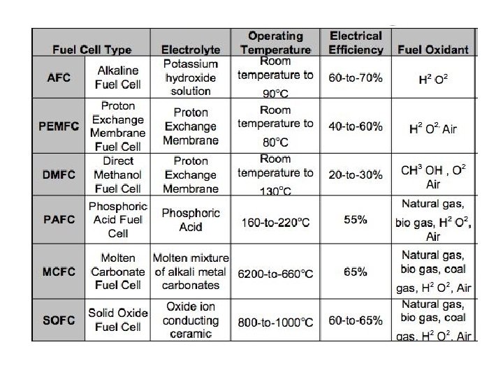
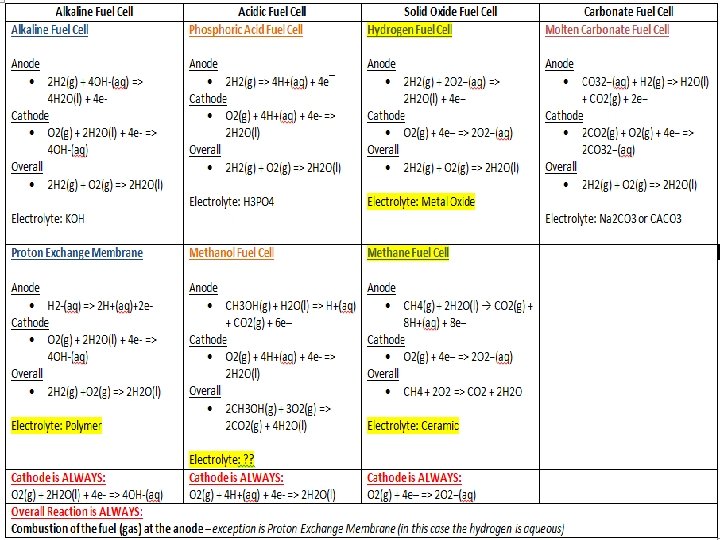
Types of Fuel cells 1. ALKALINE FULE CELL(AFC) 2. DIRECT METHANOL FUEL CELL (DMFC) 3. PHOSPHORIC ACID FUEL CELL(PAFC) 4. PROTON/POLYMER EXCHANGE MEMBRANE FUEL CELL(PEMFC) 5. MOLTEN CARBONATE FUEL CELL (MCFC) 6. SOLID OXIDE FUEL CELL (CERAMIC FUEL CELL) Manufacturing companies Ballard Generation Systems: Fuel Cell Energy (FCE): Siemens Westinghouse Power Corporation (SWPC):

Space and Other Closed Environment Power The application of fuel cells in the space program (1 k. W PEFC in the Gemini program and 1. 5 k. W AFC in the Apollo program) was demonstrated in the 1960 s. More recently, three 12 k. W AFC units were used for at least 87 missions with 65, 000 hours flight time in the Space Shuttle Orbiter. In these space applications, the fuel cells used pure reactant gases. IFC produced a H 2/O 2 30 k. W unit for the Navy’s Lockheed Deep Quest vehicle. It operates at depths of 1500 meters (5000 feet). Ballard Power Systems has produced an 80 k. W PEFC fuel cell unit for submarine use (methanol fueled) and for portable power systems.

Thermodynamic Potentials How energy can be transferred from one form to another! Combining first Law (T 1) and Second Law (T 2) d. U = Tds - pd. V

Fig. Overview of levels of fuel cell modules

Ø The first general purpose fuel cell model was a Nernst-limited model designed to compute the maximum attainable fuel cell voltage as a function of the cell operating conditions, inlet stream compositions, and desired fuel utilization. Ø Subsequently, customized unit operations models were developed to simulate the operation of solid oxide (internal reforming), molten carbonate (both external and internal reforming), phosphoric acid, and polymer electrolyte fuel cells (PEFC).

Ø Fuel cell models are lumped parameter models based on empirical performance equations. As operation deviates from the set point conditions at a "reference" state, a voltage adjustment is applied to account for perturbations. Ø Separate voltage adjustments are applied for current density, temperature, pressure, fuel utilization, fuel composition, oxidant utilization, oxidant composition, cell lifetime, and production year.
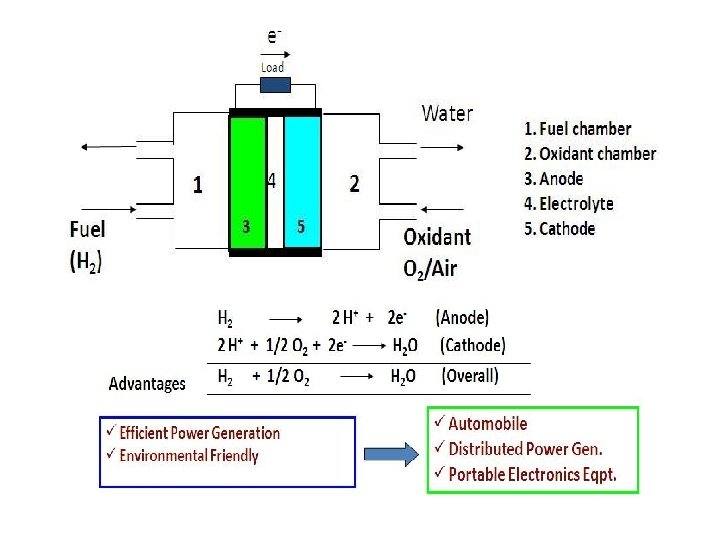

Fuel Flow Rate for 1 Ampere of Current Exercise 1: What hydrogen flow rate is required to generate 1. 0 ampere of current in a fuel cell ? For every molecule of hydrogen (H 2 ) that reacts within a fuel cell, two electrons are liberated at the fuel cell anode: H 2 ---- 2 H+ + 2 e • One ampere of current is defined as 1 C/sec. • Moles of electrons per sec. : Me = (1 [C/s])/(F [C/mol]) = 1. 0364*10 -5 mol/s • Moles of hydrogen per sec. : MH 2 = Me /2 = 0. 5182*10 -5 mol/s • Moles of hydrogen per hour: MH 2/h = 0. 01865 g mol/h • Since molar mass of H 2 is: 2. 0158 g/mol • Mass of hydrogen per hour: MH 2/h = 3. 759*10 -5 kg/h

0. 037605 kg H 2 per hour per k. A is a convenient factor that is often used to determine how much fuel must be provided to supply a desired fuel cell power output, as illustrated in the next example.
")
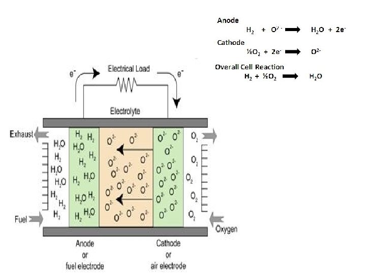
Figure : Alkaline fuel cell (AFC)

FIGURE : DIRECT METHNOL FUEL CELL
 and air, has")
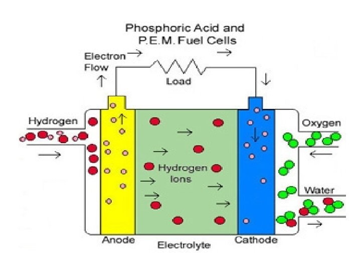
Exercise 3: A PAFC, operating on reformed natural gas (900 kg/h) and air, has a fuel and oxidant utilization of 86% and 70%, respectively. With the fuel and oxidant composition and molecular weights (MW) listed below, how much hydrogen will be consumed in mol/h? (b) How much oxygen is consumed in mol/h? (c) What is the required air flow rate in mol/h and kg/h? (d) How much water is generated? (e) What is the composition of the effluent (spent) fuel and air streams in mol percent?
: Mc_s = (900*453. 6)/(10. 55)= 38695. 7 mol/h •")
Mass of fuel supplied (mol/h): Mc_s = (900*453. 6)/(10. 55)= 38695. 7 mol/h • Mass of H 2 supplied (mol/h): MH 2 _s = Mc_s *0. 75 = 29021. 8 mol/h • Mass of H 2 consumed (mol/h): MH 2 _c = MH 2 _s *0. 86 = 24958. 7 mol/h • Mass of O 2 consumed (mol/h): MO 2 _c = MH 2 _c /2 = 12479. 4 mol/h • Mass of O 2 supplied (mol/h): MO 2 _s = MO 2_c /0. 70 = 17827. 7 mol/h • Mass of air (wet) supplied (mol/h): Mair_s = MO 2 _s /0. 2079 = 85751. 3 mol/h • Mass of air (wet) supplied (kg/h): Mair_s =85751. 3*28. 74/453. 6= 5433. 1 kg/h • Mass of water generated (mol/h): MH 2 O_G = MH 2_C = 24958. 7 mol/h
: • In PAFC, only the moles of hydrogen change on")
Fuel side: Solution (1/2): • In PAFC, only the moles of hydrogen change on the anode side • These inert gases act to dilute hydrogen lowering cell voltage Spent Fuel Effluent Calculation mol (%) kg mol/h Gas FC inlet CH 4 4. 0 CO FC reaction mol (%) FC outlet 3. 41 11. 27 0. 4 0. 34 1. 13 CO 2 17. 6 15. 01 49. 58 H 2 75. 0 63. 97 8. 96 29. 58 H 2 O 3. 0 2. 56 2. 54 8. 45 Total 100. 0 85. 29 30. 28 100. 00 -55. 01
: Air side: Mair_s = 85751. 3/453. 6=189. 04 kg mol/h Spent Air")
Solution (2/2): Air side: Mair_s = 85751. 3/453. 6=189. 04 kg mol/h Spent Air effluent Calculation mol (%) kg mol/h Gas FC inlet H 2 O 0. 70 N 2 FC reaction mol (%) FC outlet 1. 94 1. 02 57. 70 151. 71 79. 56 O 2 14. 6 40. 33 -28. 81 11. 52 6. 04 Total 100. 0 277. 11 -86. 61 190. 63 100. 00

Table : Operating/ Design parameters for the NG fueled PAFC Operating parameters Volts per Cell (V) Current density (m A/cm 2) No of stacks Cell operating temperature (C) Cell outlet pressure (bar) Overall fuel utilization (%) Overall oxidant utilization (%) DC to AC inverter efficiency (%) Auxiliary Load Value 0. 76 320 12 207 8. 0 86. 2 70. 0 97. 0 4. 2 %

TABLE : Performance Summary for the NG Fuelled PAFC Performance Parameters LHV Thermal Input (MW) Gross Fuel Cell Power (MW) Fuel Cell DC Power Inverter loss Fuel cell AC power Auxiliary power Net Power Electrical efficiency (% LHV) Electrical efficiency (% HHV) Heat Rate ( BTU/k. Wh, LHV) Value 25. 42 13. 25 0. 40 12. 85 0. 54 12. 31 48. 4 43. 7 7, 050

Schematic of Proton Exchange Membrane Fuel Cell
: Cathode (catalyst Pt/C): Polymer Electrolyte Membrane Fuel Cell")
Anode (catalyst Pt/C): Cathode (catalyst Pt/C): Polymer Electrolyte Membrane Fuel Cell

Table : Specifications of 500 W PEFC fuel cell stack available from AVISTA Labs Power Output (Continuous) 500 W Output Voltage (V) 25 To 39 DC Fuel Source Hydrogen Fuel composition 7. 0 LPM, @ 500 W ( <1. 0 LPM, @ No load) System start time 7 min @ room temperature Turndown Ratio 500 W to no load , infinity Operating temperature range (C) 5 to 35 Dimension 0. 056 m x 0. 0615 m x 0. 0345 m Weight 44 Kg/ Cartridge

Exercise : Given a desired output of 2. 0 MWDC and the desired operating point of 600 m. V and 400 m. A/cm 2 , (a) How much fuel cell area is needed? (b) Assuming a cell area of 1. 00 m 2 per cell and 280 cells per stack, how many stacks are needed for this 2. 0 MW unit? • Total current: I = P/V = 2*106 /0. 6 = 3, 333 k. A = 3. 333 MA • Cell area: A = I/Current density = =3. 333*106 /0. 4 = 8, 333 cm 2 Number of cells: N cell = A/10000 = 833 cells • Number of stacks: N stack = Ncell /280 = 2. 98 stacks≈3 stacks

Exercise : A fuel cell battery is to be used in a satellite power supply. It must deliver a steady 2 k. W at 24 V for 1 week. The mass of the cell must be the minimum possible. The fuel cell manufacturer has a design with the following characteristics: Open-circuit voltage: 1. 10 V, Internal resistivity: 92 × 10− 6 ohm m 2, Cell mass: 15 kg per m 2 of active electrode area. There is a linear relationship between VL and IL. How many cells must be connected in series? What is the total mass of all fuel cells in the battery?
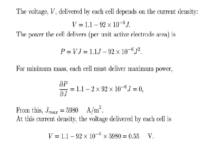
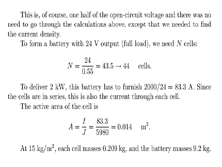

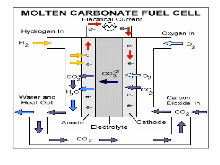
Figure : Molten Carbonate Fuel Cell
 Electrolyte : molten carbonate Cathode (Ni. O 2) Molten carbonate salt is")
Anode (Ni) Electrolyte : molten carbonate Cathode (Ni. O 2) Molten carbonate salt is used as electrolyte Operates at higher temp. , around 650 0 C Hydrocarbons can also be used as fuel, where internal reforming produces H 2 Note the flow of fuel, oxidant, products, ions and electrons through the different components of MCFC

Table : Operating design parameters for the NG Fueled IR-MCFC Operating parameters Volts per Cell (V) Current density (m. A/cm 2) No of stacks Cell operating temperature (C) Cell outlet pressure (bar) fuel utilization (%) Oxidant utilization (%) DC to AC inverter efficiency (%) Auxiliary Load Value 0. 76 320 12 207 8. 0 78. 2 75. 0 95. 0 4. 2 %

Table : Overall Performance summary for the NG fuelled IR-MCFC Performance Parameters LHV Thermal Input (MW) Gross Fuel Cell Power (MW) Fuel Cell DC Power Inverter loss Fuel cell AC power Value 4. 8 Auxiliary power Net Power Electrical efficiency (% LHV) Heat Rate ( BTU/k. Wh, LHV) 0. 05 2. 81 58. 4 5900 3. 0 0. 15 2. 85

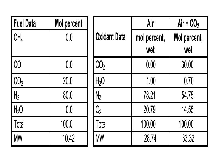
MCFC Effluent Composition - Ignoring the Water Gas Shift Reaction Exercise : An MCFC operating on 1, 000 kg/h of fuel gas and a 70 % air/30 % CO 2 oxidant has a fuel and oxidant utilization of 75% and 50% respectively. With the fuel and oxidant composition and molecular weights listed below, (a) How much hydrogen will be consumed in mol/h? (b) How much oxygen is consumed in mol/h? (c) What are the required air and oxidant flow rates in mol/h? (d) How much CO 2 is transferred from the cathode to the anode? (e) What is the composition of the effluent (spent) fuel and oxidant streams in mol percent (no water gas shift reaction)?
: • in the MCFC, • Mass of fuel supplied (mol/h):")
• Solution (1/2): • in the MCFC, • Mass of fuel supplied (mol/h): Mc_s =(1000*453. 6)/(10. 42)= 43531. 67 mol/h • Mass of H 2 supplied (mol/h): MH 2_s = M c_s *0. 80 = 34825. 3 mol/h • Mass of H 2 consumed (mol/h): MH 2_c = M H 2_s *0. 75 = 26119. 0 mol/h • Mass of O 2 consumed (mol/h): MO 2_c = M H 2_c /2 = 13059. 5 mol/h • Mass of air (wet) supplied: Mair_s = ((MO 2_c /0. 50)/0. 2079)=125632. 5 mol/h • Mass of oxidant supplied (mol/h): Mox_s =M air_s /0. 70 = 179475. 0 mol/h • Since: H 2, anode +1/2 O 2 cathode +CO 2 , cathode --- H 2 O , anode + CO 2, anode • Mass of CO 2 transferred= consumed (mol/h): MCO 2_t =M H 2_c =26119. 0 mol/h • Fuel side: in the MCFC, both oxygen and carbon dioxide are consumed on the cathode(air) side.
 mol (%) kg mol/h Gas FC inlet CH")
Spent Fuel Effluent Calculation (Fuel side) mol (%) kg mol/h Gas FC inlet CH 4 0. 0 CO FC reaction mol (%) FC outlet 0. 00 0. 00 CO 2 20. 0 19. 20 57. 61 76. 82 50. 00 H 2 80. 0 76. 82 -57. 61 19. 20 12. 50 H 2 O 0. 00 57. 61 37. 50 Total 100. 0 96. 02 -57. 61 153. 63 100. 00
: Mair_s = 125632. 5/453. 6=277 kg mol/h Spent Oxidant effluent Calculation (Air")
Solution (2/2): Mair_s = 125632. 5/453. 6=277 kg mol/h Spent Oxidant effluent Calculation (Air Side) mol (%) kg mol/h mol (%) Gas FC inlet FC reaction FC outlet CO 2 30. 00 83. 10 -57. 61 25. 52 13. 38 H 2 O 0. 70 1. 94 1. 02 N 2 57. 70 151. 71 79. 56 O 2 14. 6 40. 33 -28. 81 11. 52 6. 04 Total 100. 0 277. 11 -86. 61 190. 63 100. 00

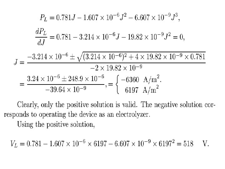
Exercise : Solid Oxide fuel cells manufactured by Siemens Westinghouse have a very pronounced curvature in their V-J characteristics. One class of cells using “ribbed” units behave according to VL = 0. 781 − 1. 607 × 10− 6 J − 6. 607 × 10− 9 J 2, where J is the current density in A/m 2 and VL is the load voltage in V. a) What is the open-circuit voltage of the cell? The open circuit of the cell is 0. 781 V. b) What is the voltage of the cell when delivering maximum power to a load?

FUEL CELL SYSTEM OPTIMIZATION

- Slides: 46