
FTK crates power supplies and cooling issues Racks
- Slides: 13
FTK crates, power supplies and cooling issues Ø Racks, crates and PS: requirements Ø Wiener crates Ø Rittal crates Ø Mixed crates Ø Cooling tests and first results Ø Next steps 13/03/2013 FTK-IAPP workshop - A. Lanza 1
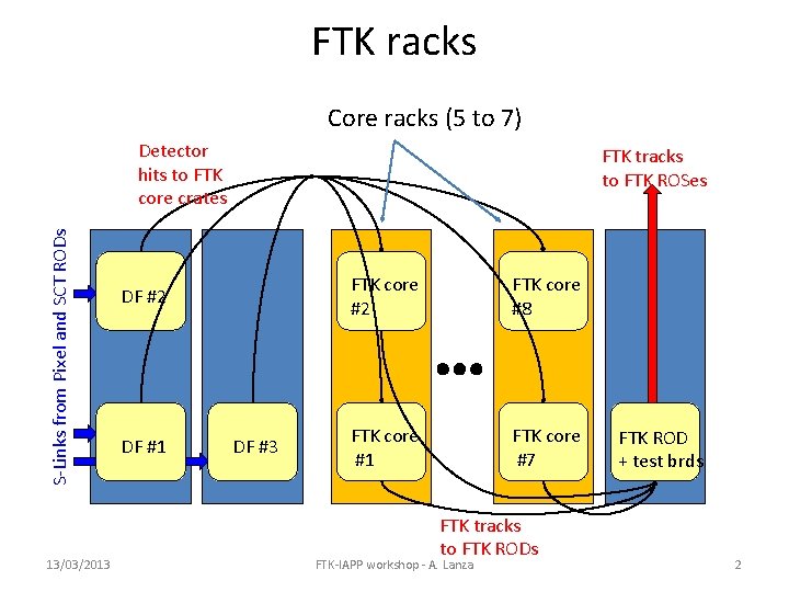
FTK racks Core racks (5 to 7) S-Links from Pixel and SCT RODs Detector hits to FTK core crates 13/03/2013 FTK tracks to FTK ROSes DF #2 DF #1 DF #3 FTK core #2 FTK core #8 FTK core #1 FTK core #7 FTK tracks to FTK RODs FTK-IAPP workshop - A. Lanza FTK ROD + test brds 2
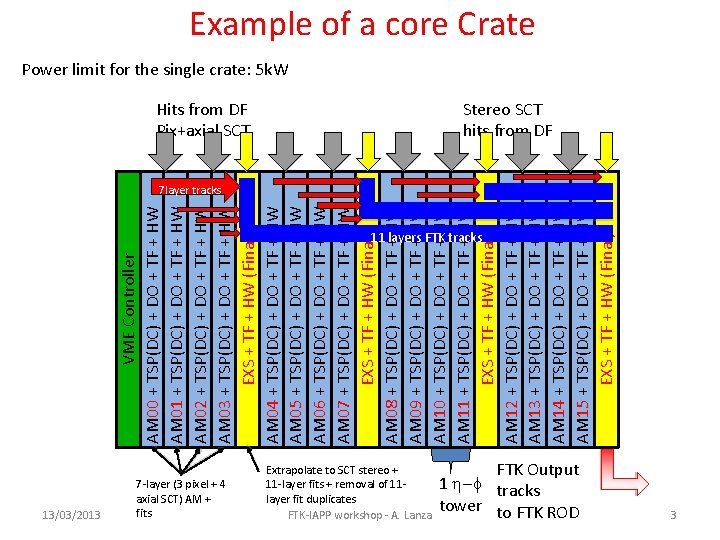
VME Controller AM 00 + TSP(DC) + DO + TF + HW AM 01 + TSP(DC) + DO + TF + HW AM 02 + TSP(DC) + DO + TF + HW AM 03 + TSP(DC) + DO + TF + HW EXS + TF + HW (Final) AM 04 + TSP(DC) + DO + TF + HW AM 05 + TSP(DC) + DO + TF + HW AM 06 + TSP(DC) + DO + TF + HW AM 07 + TSP(DC) + DO + TF + HW EXS + TF + HW (Final) AM 08 + TSP(DC) + DO + TF + HW AM 09 + TSP(DC) + DO + TF + HW AM 10 + TSP(DC) + DO + TF + HW AM 11 + TSP(DC) + DO + TF + HW EXS + TF + HW (Final) AM 12 + TSP(DC) + DO + TF + HW AM 13 + TSP(DC) + DO + TF + HW AM 14 + TSP(DC) + DO + TF + HW AM 15 + TSP(DC) + DO + TF + HW EXS + TF + HW (Final) Example of a core Crate Power limit for the single crate: 5 k. W Hits from DF Pix+axial SCT 13/03/2013 7 -layer (3 pixel + 4 axial SCT) AM + fits Stereo SCT hits from DF 7 layer tracks 11 layers FTK tracks Extrapolate to SCT stereo + 11 -layer fits + removal of 11 layer fit duplicates FTK-IAPP workshop - A. Lanza FTK Output 1 h-f tracks tower to FTK ROD 3
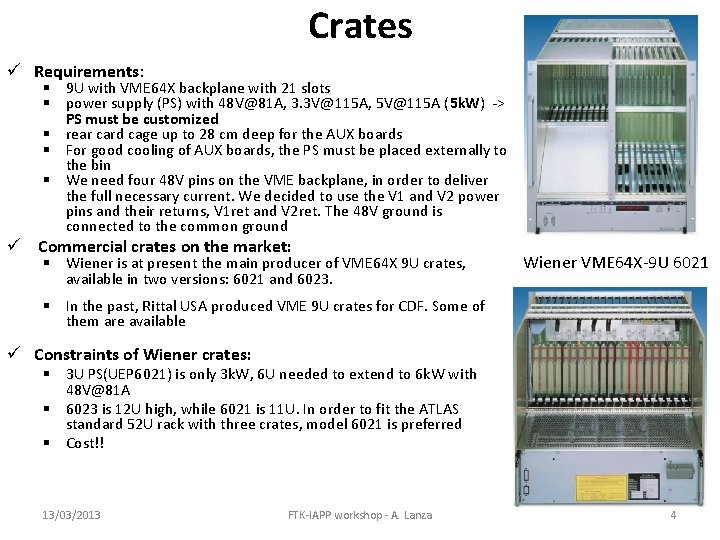
Crates ü Requirements: § 9 U with VME 64 X backplane with 21 slots § power supply (PS) with 48 V@81 A, 3. 3 V@115 A, 5 V@115 A (5 k. W) -> PS must be customized § rear card cage up to 28 cm deep for the AUX boards § For good cooling of AUX boards, the PS must be placed externally to the bin § We need four 48 V pins on the VME backplane, in order to deliver the full necessary current. We decided to use the V 1 and V 2 power pins and their returns, V 1 ret and V 2 ret. The 48 V ground is connected to the common ground ü Commercial crates on the market: § Wiener is at present the main producer of VME 64 X 9 U crates, available in two versions: 6021 and 6023. Wiener VME 64 X-9 U 6021 § In the past, Rittal USA produced VME 9 U crates for CDF. Some of them are available ü Constraints of Wiener crates: § 3 U PS(UEP 6021) is only 3 k. W, 6 U needed to extend to 6 k. W with 48 V@81 A § 6023 is 12 U high, while 6021 is 11 U. In order to fit the ATLAS standard 52 U rack with three crates, model 6021 is preferred § Cost!! 13/03/2013 FTK-IAPP workshop - A. Lanza 4
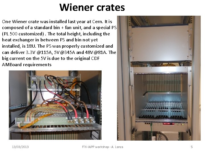
Wiener crates One Wiener crate was installed last year at Cern. It is composed of a standard bin + fan unit, and a special PS (PL 500 customized). The total height, including the heat exchanger in between PS and bin not yet installed, is 18 U. The PS was properly customized and can deliver 3. 3 V @115 A, 5 V@345 A and 48 V@81 A. The big current on the 5 V is due to the original CDF AMBoard requirements 13/03/2013 FTK-IAPP workshop - A. Lanza 5
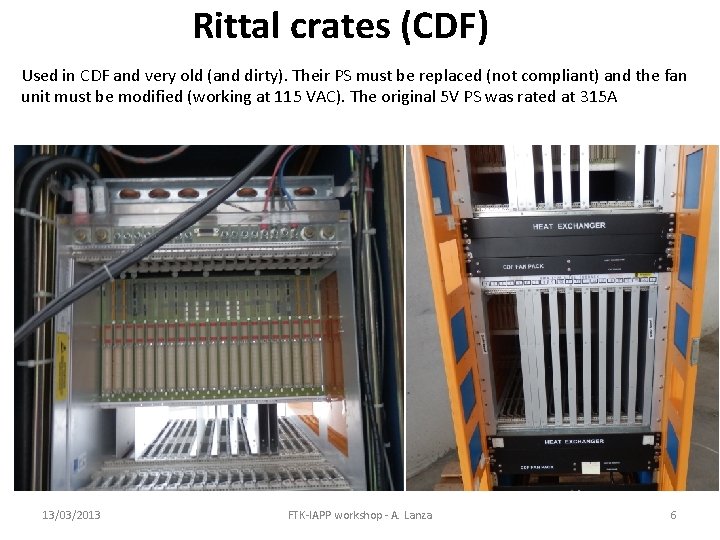
Rittal crates (CDF) Used in CDF and very old (and dirty). Their PS must be replaced (not compliant) and the fan unit must be modified (working at 115 VAC). The original 5 V PS was rated at 315 A 13/03/2013 FTK-IAPP workshop - A. Lanza 6
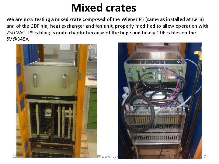
Mixed crates We are now testing a mixed crate composed of the Wiener PS (same as installed at Cern) and of the CDF bin, heat exchanger and fan unit, properly modified to allow operation with 230 VAC. PS cabling is quite chaotic because of the huge and heavy CDF cables on the 5 V@345 A 13/03/2013 FTK-IAPP workshop - A. Lanza 7
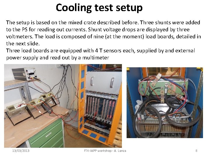
Cooling test setup The setup is based on the mixed crate described before. Three shunts were added to the PS for reading out currents. Shunt voltage drops are displayed by three voltmeters. The load is composed of nine (at the moment) load boards, detailed in the next slide. Three load boards are equipped with 4 T sensors each, supplied by and external power supply and read out by a multimeter 13/03/2013 FTK-IAPP workshop - A. Lanza 8
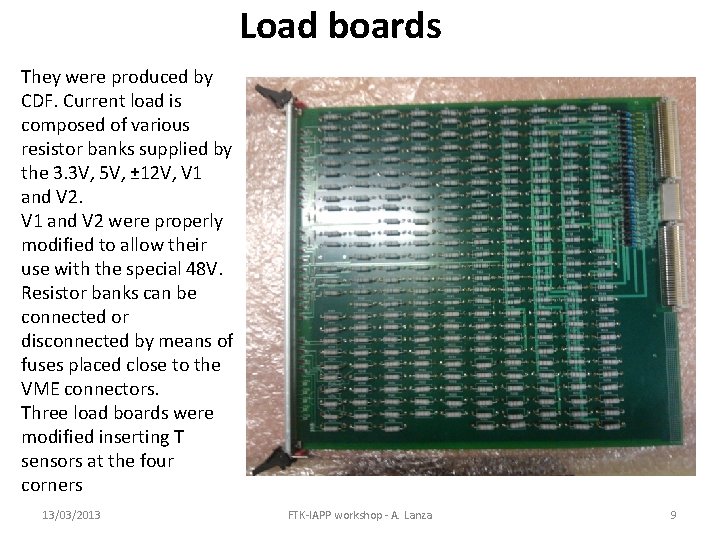
Load boards They were produced by CDF. Current load is composed of various resistor banks supplied by the 3. 3 V, 5 V, ± 12 V, V 1 and V 2 were properly modified to allow their use with the special 48 V. Resistor banks can be connected or disconnected by means of fuses placed close to the VME connectors. Three load boards were modified inserting T sensors at the four corners 13/03/2013 FTK-IAPP workshop - A. Lanza 9
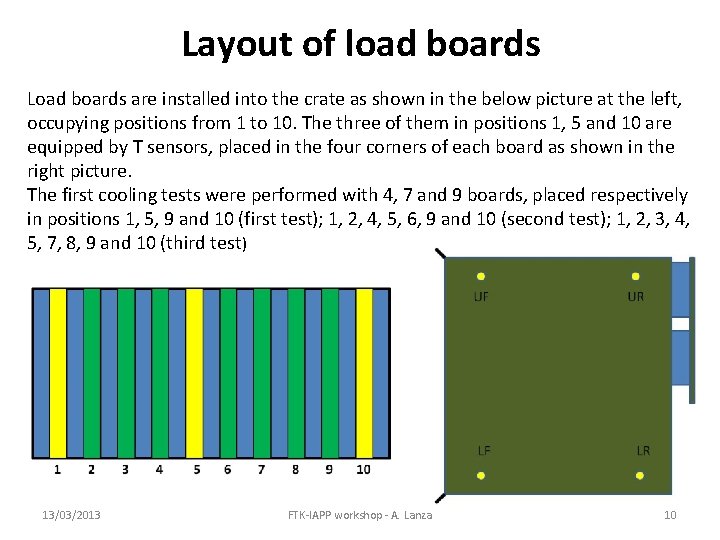
Layout of load boards Load boards are installed into the crate as shown in the below picture at the left, occupying positions from 1 to 10. The three of them in positions 1, 5 and 10 are equipped by T sensors, placed in the four corners of each board as shown in the right picture. The first cooling tests were performed with 4, 7 and 9 boards, placed respectively in positions 1, 5, 9 and 10 (first test); 1, 2, 4, 5, 6, 9 and 10 (second test); 1, 2, 3, 4, 5, 7, 8, 9 and 10 (third test) 13/03/2013 FTK-IAPP workshop - A. Lanza 10
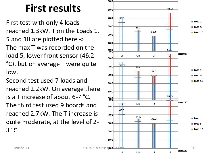
60. 0 First results 46. 2 50. 0 First test with only 4 loads reached 1. 3 k. W. T on the Loads 1, 5 and 10 are plotted here -> The max T was recorded on the load 5, lower front sensor (46. 2 °C), but on average T were quite low. Second test used 7 loads and reached 2. 2 k. W. On average there is a T increase of about 6 -7 °C. The third test used 9 boards and reached 2. 7 k. W. The T increase is quite moderate, at the level of 23 °C 40. 0 34. 7 30. 0 Load 1 Load 5 23. 7 18. 6 20. 0 Load 10 10. 0 60. 0 50. 0 40. 0 54. 9 UF UR 36. 3 34. 7 LR LF Load 10 1 5 Load 1 29. 2 30. 0 Load 5 Load 10 20. 0 10. 0 57. 0 60. 0 50. 0 UF UR LR 32. 0 30. 2 LF Load 10 1 5 40. 0 Load 1 30. 0 Load 5 Load 10 20. 0 13/03/2013 FTK-IAPP workshop 0. 0 - A. Lanza UF UR LR LF Load 10 1 5 11
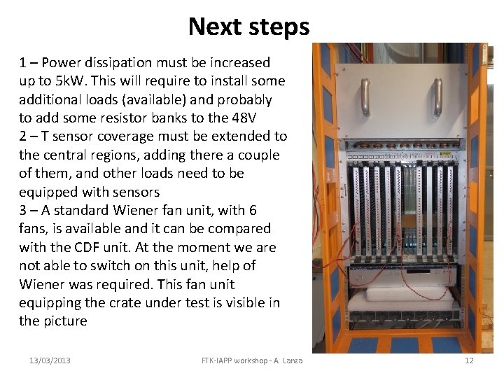
Next steps 1 – Power dissipation must be increased up to 5 k. W. This will require to install some additional loads (available) and probably to add some resistor banks to the 48 V 2 – T sensor coverage must be extended to the central regions, adding there a couple of them, and other loads need to be equipped with sensors 3 – A standard Wiener fan unit, with 6 fans, is available and it can be compared with the CDF unit. At the moment we are not able to switch on this unit, help of Wiener was required. This fan unit equipping the crate under test is visible in the picture 13/03/2013 FTK-IAPP workshop - A. Lanza 12
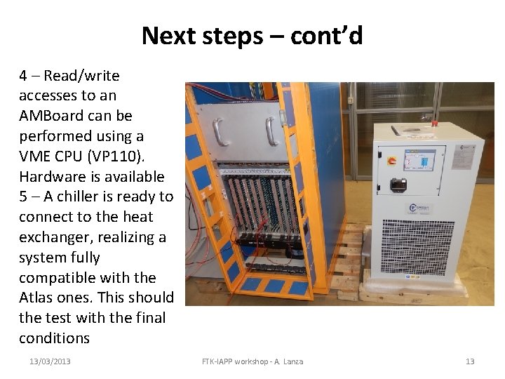
Next steps – cont’d 4 – Read/write accesses to an AMBoard can be performed using a VME CPU (VP 110). Hardware is available 5 – A chiller is ready to connect to the heat exchanger, realizing a system fully compatible with the Atlas ones. This should the test with the final conditions 13/03/2013 FTK-IAPP workshop - A. Lanza 13