
Frontiers of midIR lasers based on transition metal

Frontiers of mid-IR lasers based on transition metal doped chalcogenides. Optically Pumped CO 2 Lasers and Amplifiers S. Mirov 1, 2, D. Martyshkin, 1 V. Fedorov, 1 K. Karki, 1 I. Moskalev 2, S. Vasilyev 2, M. Mirov 2, J. Peppers 2, V. Smolski 2 D. Tovey, 3 J. J. Pigeon, 3 S. Ya. Tochitsky, 3 I. Ben-Zvi, 4 and C. Joshi 3, I. Pogorelsky 5, M. Polyanskiy 5 1 Department of Physics, University of Alabama at Birmingham, CH 310, 1300 University Blvd. , Birmingham, AL 35294, USA 2 IPG Photonics - Southeast Technology Center, 100 Lucerne Ln, Birmingham, Al 35211, USA 3 University of California, Los Angeles 4 Stony Brook University 5 Brookhaven National lab Author e-mail address: mirov@uab. edu Funding: The work reported here partially involves intellectual property developed at the University of Alabama at Birmingham (UAB). This intellectual property has been licensed to the IPG Photonics Corporation. The UAB co-authors declare competing financial interests. Department of Energy (DOE) Office of Science Accelerator Stewardship award (DE-SC 0018378) 1 October 15, 2019 ATF Science Planning Workshop, LWIR Laser Capabilities

Outline 1. Motivation. Why Optically pumped CO 2 lasers/amplifiers 2. TM: II-VI MIR laser materials introduction (Fe: Cr: Zn. S/Zn. Se ) 3. Cr: Zn. S/Zn. Se oscillators and amplifiers 4. Fe: II-VI oscillators and amplifiers at 4 -5 m 5. Fe: Zn. Se pumped CO 2 lasers/amplifiers 001 6. Conclusions and Outlook 100 4. 3 m 10 m CO 2 Levels 000 2

Ultrafast MIR laser sources : Motivation and Technologies • Goal: produce high power (1 TW), short (<1 ps) pulses in LWIR • Down conversion of near-IR lasers (Ti-S, Yb, Er) in (2), (3) materials □ □ ─ ‒ I. Pupeza et al. , Nature Photon. 9, 721 (2015). Well established near-IR fiber, bulk, thin disk fs lasers Well established conversion techniques: OPCPA, DFG, OPO, SCG. Complex setups, difficult to remain efficient for λ > 5 µm • Direct fs lasing in the MIR + OPCPA, DFG, OPO, SCG + □ □ □ Most compact, efficient, and high power fs sources ‒ J. Zhang et al. , Light: Science & Applications 7, 17180 (2018) 2 µm Tm-, Ho-doped bulk, thin disk, ‒ M. Gebhardt et al. , Opt. Lett. 42, 4179 (2017) silica-based fiber lasers 3 µm Er-, Ho-doped fluoride-based fiber lasers 2— 3 µm Cr: Zn. S and Cr: Zn. Se lasers ‒ S. Mirov et al. , IEEE JSTQE 24, 1601829 (2018) 3. 4— 5 µm Fe: Zn. S and Fe: Zn. Se lasers - A. Ongstad et al. , SPIE Defense and Security, 2018 - A. D. Martinez et al. , Opt. Mat. Express 5(9). 2036 -2046 (2015). 4— 8 µm Fe: Cd. Zn. Te lasers Room-temperature cross-sections of emission of (i) Cr: Zn. S, ii) Cr: Zn. Se ; iii) Fe: Zn. S, iv) Fe: Zn. Se, v) Fe: Cd 0. 75 Mn 0. 25 Se, vi) Fe: Cd. Te, vii) Fe: Zn 0. 5 Cd 0. 5 Te, and viii) Fe: Cd 0. 5 Mn 0. 5 Te 55 -80 μs radiative lifetime - High energy storage capability. Promising mid-IR amplifiers of ns-fs pulses! 3
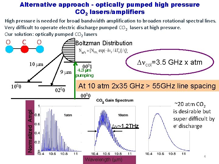
Alternative approach - optically pumped high pressure CO 2 lasers/amplifiers High pressure is needed for broad bandwidth amplification to broaden rotational spectral lines. Very difficult to operate electric discharge pumped CO 2 lasers at high pressure. Our solution: optically pumped CO 2 lasers O C O Boltzman Distribution 10 m 9 m 1000 Normalized Ampl. . 0200 col=3. 5 GHz x atm 0001 4. 3 μm pumping At 10 atm 2 x 35 GHz > 55 GHz line spacing 0000 ~1. 2 THz Wavelength ( m) ~20 atm CO 2 is desirable but super difficult by e- discharge 4
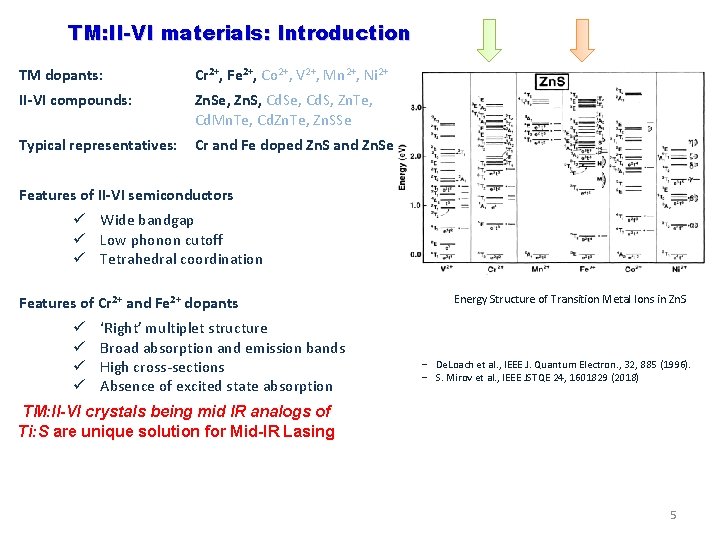
TM: II-VI materials: Introduction TM dopants: Cr 2+, Fe 2+, Co 2+, V 2+, Mn 2+, Ni 2+ II-VI compounds: Zn. Se, Zn. S, Cd. Se, Cd. S, Zn. Te, Cd. Mn. Te, Cd. Zn. Te, Zn. SSe Typical representatives: Cr and Fe doped Zn. S and Zn. Se Features of II-VI semiconductors ü Wide bandgap ü Low phonon cutoff ü Tetrahedral coordination Features of Cr 2+ and Fe 2+ dopants ü ü ‘Right’ multiplet structure Broad absorption and emission bands High cross-sections Absence of excited state absorption Energy Structure of Transition Metal Ions in Zn. S ‒ De. Loach et al. , IEEE J. Quantum Electron. , 32, 885 (1996). ‒ S. Mirov et al. , IEEE JSTQE 24, 1601829 (2018) TM: II-VI crystals being mid IR analogs of Ti: S are unique solution for Mid-IR Lasing 5
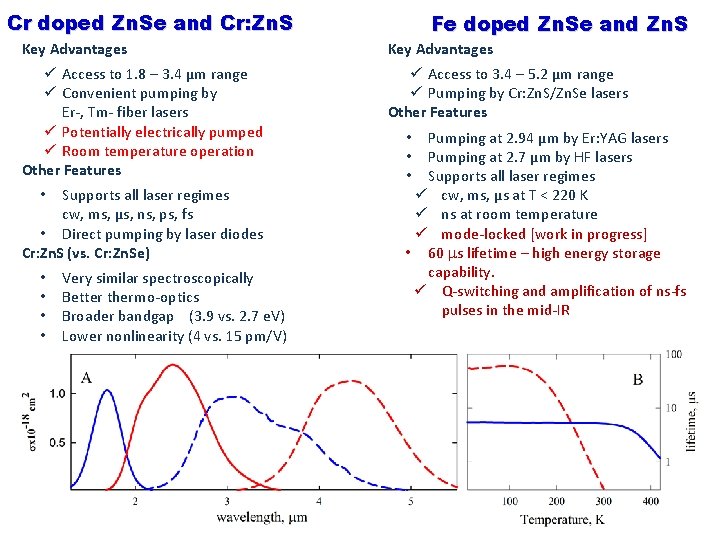
Cr doped Zn. Se and Cr: Zn. S Fe doped Zn. Se and Zn. S Key Advantages ü Access to 1. 8 – 3. 4 µm range ü Convenient pumping by Er-, Tm- fiber lasers ü Potentially electrically pumped ü Room temperature operation Other Features ü Access to 3. 4 – 5. 2 µm range ü Pumping by Cr: Zn. S/Zn. Se lasers Other Features Supports all laser regimes cw, ms, µs, ns, ps, fs • Direct pumping by laser diodes Cr: Zn. S (vs. Cr: Zn. Se) • • • Very similar spectroscopically Better thermo-optics Broader bandgap (3. 9 vs. 2. 7 e. V) Lower nonlinearity (4 vs. 15 pm/V) Pumping at 2. 94 µm by Er: YAG lasers Pumping at 2. 7 µm by HF lasers Supports all laser regimes ü cw, ms, µs at T < 220 K ü ns at room temperature ü mode-locked [work in progress] • 60 s lifetime – high energy storage capability. ü Q-switching and amplification of ns-fs pulses in the mid-IR • • • Fe: Zn. S vs. Fe: Zn. Se • Very similar spectroscopically 6
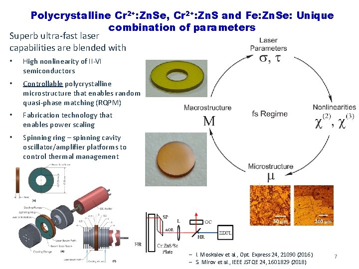
Polycrystalline Cr 2+: Zn. Se, Cr 2+: Zn. S and Fe: Zn. Se: Unique combination of parameters Superb ultra-fast laser capabilities are blended with • High nonlinearity of II-VI semiconductors • Controllable polycrystalline microstructure that enables random quasi-phase matching (RQPM) • Fabrication technology that enables power scaling • Spinning ring – spinning cavity oscillator/amplifier platforms to control thermal management ‒ I. Moskalev et al. , Opt. Express 24, 21090 (2016) ‒ S. Mirov et al. , IEEE JSTQE 24, 1601829 (2018) 7
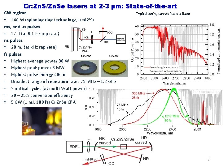
Cr: Zn. S/Zn. Se lasers at 2 -3 µm: State-of-the-art CW regime • 140 W (spinning ring technology, =62%) ms, and µs pulses • 1. 1 J (at 0. 1 Hz rep rate) ns pulses • 20 m. J (at k. Hz rep rate) fs pulses • Highest average power 30 W • Highest peak power 8 MW • Highest pulse energy 400 n. J • Broadest range of repetition rates 75 MHz – 1. 2 GHz • 2 optical cycles (at multi-Watt power) • 20 – 25% conversion efficiency • 5 GW (1 m. J, 100 fs) Cr: Zn. Se CPA Typical tuning curve of cw oscillator 8
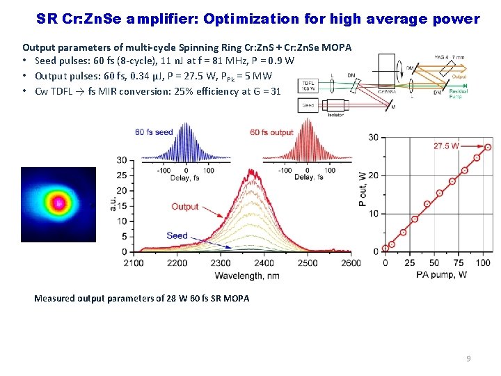
SR Cr: Zn. Se amplifier: Optimization for high average power Output parameters of multi-cycle Spinning Ring Cr: Zn. S + Cr: Zn. Se MOPA • Seed pulses: 60 fs (8 -cycle), 11 n. J at f = 81 MHz, P = 0. 9 W • Output pulses: 60 fs, 0. 34 µJ, P = 27. 5 W, PPk = 5 MW • Cw TDFL → fs MIR conversion: 25% efficiency at G = 31 Measured output parameters of 28 W 60 fs SR MOPA 9
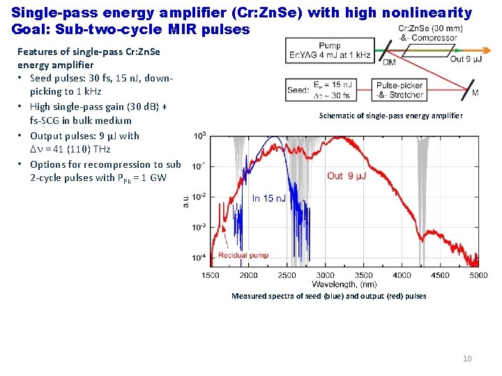
Single-pass energy amplifier (Cr: Zn. Se) with high nonlinearity Goal: Sub-two-cycle MIR pulses Features of single-pass Cr: Zn. Se energy amplifier • Seed pulses: 30 fs, 15 n. J, downpicking to 1 k. Hz • High single-pass gain (30 d. B) + fs-SCG in bulk medium • Output pulses: 9 µJ with = 41 (110) THz • Options for recompression to sub 2 -cycle pulses with PPk = 1 GW Schematic of single-pass energy amplifier Measured spectra of seed (blue) and output (red) pulses 10
11
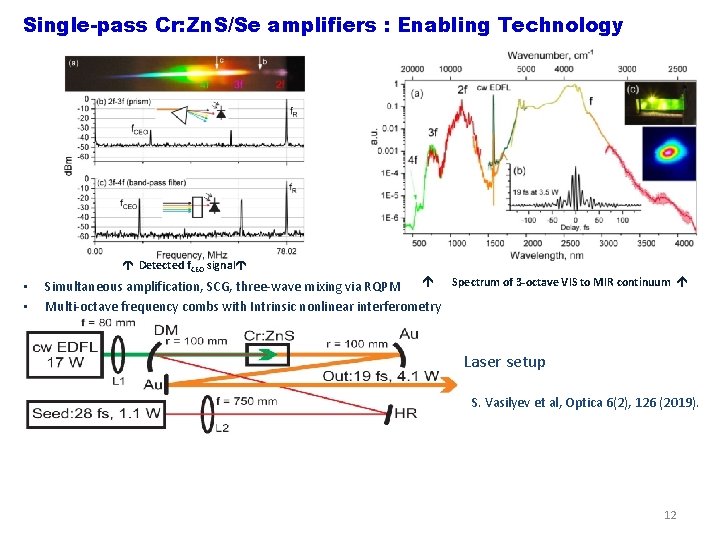
Single-pass Cr: Zn. S/Se amplifiers : Enabling Technology Detected f. CEO signal • • Spectrum of 3 -octave VIS to MIR continuum Simultaneous amplification, SCG, three-wave mixing via RQPM Multi-octave frequency combs with Intrinsic nonlinear interferometry Laser setup S. Vasilyev et al, Optica 6(2), 126 (2019). 12
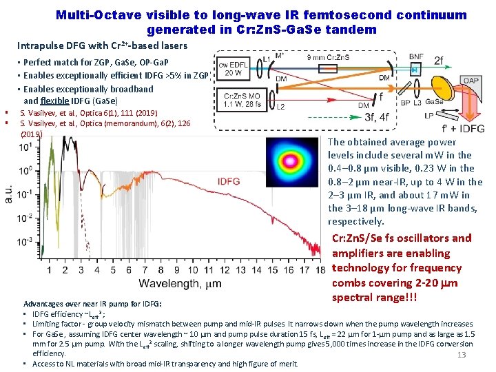
Multi-Octave visible to long-wave IR femtosecond continuum generated in Cr: Zn. S-Ga. Se tandem Intrapulse DFG with Cr 2+-based lasers • Perfect match for ZGP, Ga. Se, OP-Ga. P • Enables exceptionally efficient IDFG >5% in ZGP) • Enables exceptionally broadband flexible IDFG (Ga. Se) § § S. Vasilyev, et al. , Optica 6(1), 111 (2019) S. Vasilyev, et al. , Optica (memorandum), 6(2), 126 (2019) The obtained average power levels include several m. W in the 0. 4– 0. 8 µm visible, 0. 23 W in the 0. 8– 2 µm near-IR, up to 4 W in the 2– 3 µm IR, and about 17 m. W in the 3– 18 µm long-wave IR bands, respectively. Cr: Zn. S/Se fs oscillators and amplifiers are enabling technology for frequency combs covering 2 -20 m spectral range!!! Advantages over near IR pump for IDFG: • IDFG efficiency ~Leff 2 ; • Limiting factor - group velocity mismatch between pump and mid-IR pulses. It narrows down when the pump wavelength increases. • For Ga. Se , assuming IDFG center wavelength ~ 10 µm and pump pulse duration 15 fs, L eff = 22 µm for 1 -µm pump and as large as 1. 5 mm for 2. 5 µm pump. With the Leff 2 scaling, shifting to a longer wavelength pump gives 5, 000 times increase in the IDFG conversion efficiency. 13 • Access to NL materials with broad mid-IR transparency and high figure of merit.
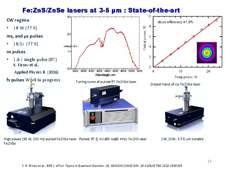
Fe: Zn. S/Zn. Se lasers at 3 -5 µm : State-of-the-art CW regime • 10 W (77 K) ms, and µs pulses • 10. 5 J (77 K) ns pulses • 1. 6 J single pulse (RT) K. Firsov et al. , Applied Physics B (2016) fs pulses Work in progress Tuning curve of pulsed RT Fe: Zn. Se laser High power (35 W, 100 Hz) pulsed Fe: Zn. Se laser Pulsed, RT (1 m. J @5 ns@1 k. Hz) Fe: Zn. S laser Fe: Zn. Se Output-Input of cw Fe: Zn. Se laser CW, 10 W, 3. 7 -5 um tunable 14 S. B. Mirov et al. , IEEE J. of Sel. Topics in Quantum Electron. 24, 1601829 (2018) DOI: 10. 1109/JSTQE. 2018. 2808284.

20 atm Optically Pumped CO 2 Laser UCLA We will combine the best of gas laser and SSL technologies to generate a~1 ps, 100 GW LWIR pulses: dramatic reduction of size and amplification of shorter pulses. Ultimate goal is a compact TW power CO 2 laser pumped by 4. 3 mm Fe: Zn. Se laser. 001 100 4. 3 m 10 m CO 2 Levels 10 m 500 fs OPA Seed 4. 3 m Fe: Zn. Se Laser 10 m 1 ps, 10 -100 GW 000 20 atm 12 CO --13 CO —He 2 2 Gain Spectrum Collaboration between UCLA/BNL/UAB 15
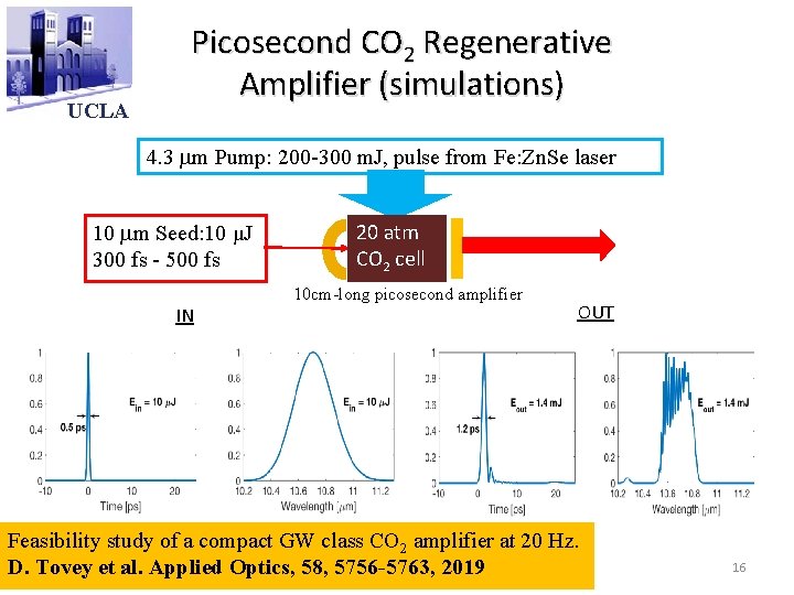
UCLA Picosecond CO 2 Regenerative Amplifier (simulations) 4. 3 m Pump: 200 -300 m. J, pulse from Fe: Zn. Se laser 10 m Seed: 10 μJ 300 fs - 500 fs IN 20 atm CO 2 cell 10 cm-long picosecond amplifier OUT Feasibility study of a compact GW class CO 2 amplifier at 20 Hz. D. Tovey et al. Applied Optics, 58, 5756 -5763, 2019 16
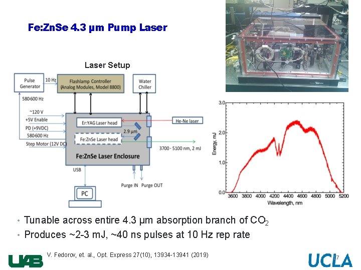
Fe: Zn. Se 4. 3 µm Pump Laser Setup Tuning Curve • Tunable across entire 4. 3 µm absorption branch of CO 2 • Produces ~2 -3 m. J, ~40 ns pulses at 10 Hz rep rate V. Fedorov, et. al. , Opt. Express 27(10), 13934 -13941 (2019) 17
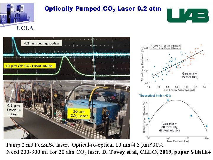
Optically Pumped CO 2 Laser 0. 2 atm UCLA MARS Pump 2 m. J Fe: Zn. Se laser, Optical-to-optical 10 m/4. 3 m≤ 30%. Need 200 -300 m. J for 20 atm CO 2 laser. D. Tovey et al, CLEO, 2019, paper STh 1 E 4 18
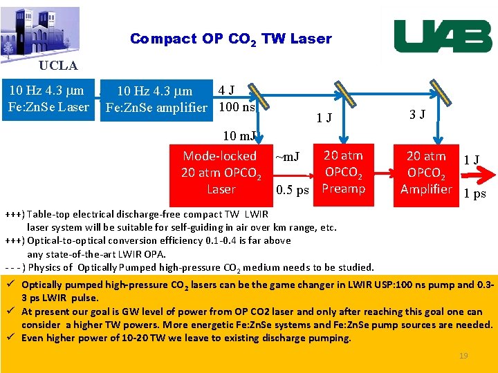
Compact OP CO 2 TW Laser UCLA 10 Hz 4. 3 m Fe: Zn. Se Laser 4 J 10 Hz 4. 3 m Fe: Zn. Se amplifier 100 ns 10 m. J Mode-locked 20 atm OPCO 2 Laser 1 J MARS 20 atm ~m. J OPCO 2 0. 5 ps Preamp 3 J 20 atm 1 J OPCO 2 Amplifier 1 ps +++) Table-top electrical discharge-free compact TW LWIR laser system will be suitable for self-guiding in air over km range, etc. +++) Optical-to-optical conversion efficiency 0. 1 -0. 4 is far above any state-of-the-art LWIR OPA. - - - ) Physics of Optically Pumped high-pressure CO 2 medium needs to be studied. ü Optically pumped high-pressure CO 2 lasers can be the game changer in LWIR USP: 100 ns pump and 0. 33 ps LWIR pulse. ü At present our goal is GW level of power from OP CO 2 laser and only after reaching this goal one can consider a higher TW powers. More energetic Fe: Zn. Se systems and Fe: Zn. Se pump sources are needed. ü Even higher power of 10 -20 TW we leave to existing discharge pumping. 19
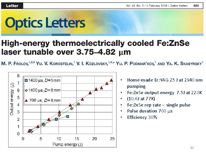
• Home-made Er: YAG 25 J at 2940 nm pumping • Fe: Zn. Se output energy 7. 5 J at 220 K • (10. 6 J at 77 K) • Fe: Zn. Se rep rate – single pulse • Pulse duration 700 s • Efficiency 30% 20
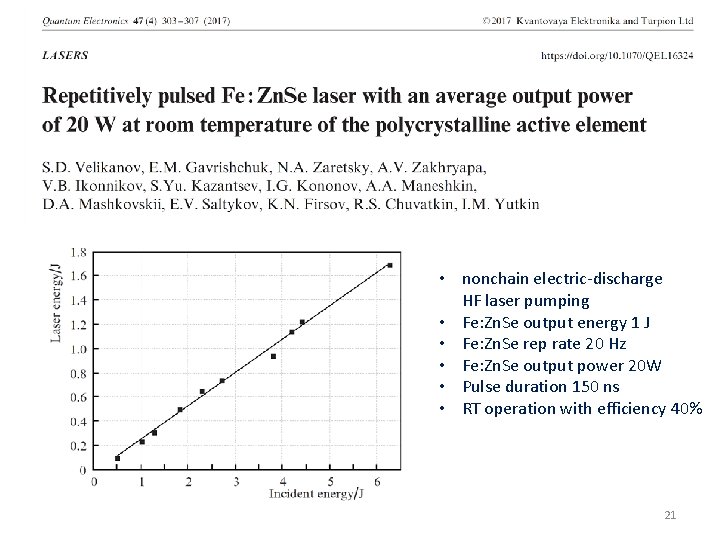
• nonchain electric-discharge HF laser pumping • Fe: Zn. Se output energy 1 J • Fe: Zn. Se rep rate 20 Hz • Fe: Zn. Se output power 20 W • Pulse duration 150 ns • RT operation with efficiency 40% 21
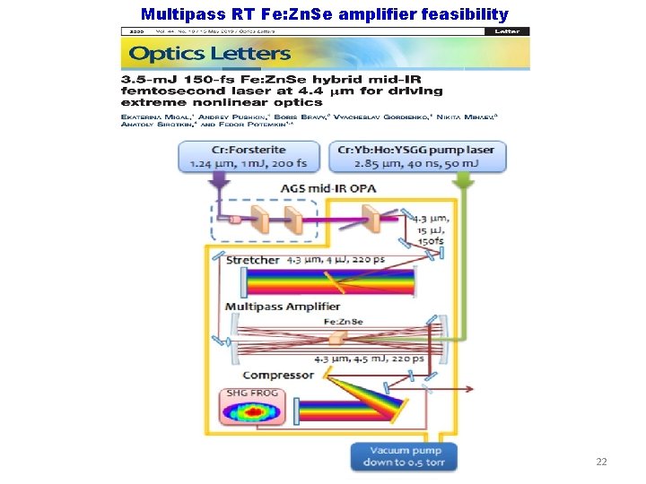
Multipass RT Fe: Zn. Se amplifier feasibility 22
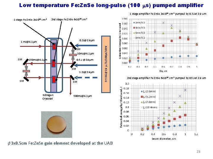
Low temperature Fe: Zn. Se long-pulse (100 s) pumped amplifier 1 stage amplifier Fe: Zn. Se 2 x 1019 cm-3 pumped by 0. 3 J at 2. 9 um 1 stage Fe: Zn. Se 2 x 10 19 cm-3 2 nd stage Fe: Zn. Se 6 x 10 18 cm-3 SM 10 m. J@4. 1µm SM 150 m. J@4. 1µm 0. 5. J @2. 9µm SM SM 1. 2 J@2. 9µm SM Nitrogen Cryostat Er: YAG@2. 9 µ /2 J/100µs/10 Hz 0. 3 J@2. 9µm 1 m. J@4. 1µm 2 nd stage amplifier Fe: Zn. Se 6 x 1018 cm-3 pumped by 0. 5 J at 2. 9 um 500 m. J@4. 1µm 3 x 0. 5 cm Fe: Zn. Se gain element developed at the UAB 23
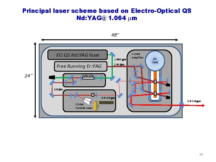
Principal laser scheme based on Electro-Optical QS Nd: YAG@ 1. 064 m 48’’ EO QS Nd: YAG laser 1. 064 m Free Running Er: YAG 24’’ 2. 94 m F: Zn. Se Amplifier LN Tank OPO KTA 3. 0 m 3. 9 -5. 0 m F: Zn. Se Tunable Laser 3. 9 -5. 0 m 24
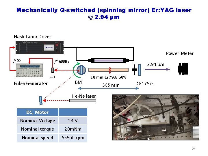
Mechanically Q-switched (spinning mirror) Er: YAG laser @ 2. 94 µm Flash Lamp Driver Power Meter f/60 f~ 600 Hz PD Pulse Generator 2. 94 m BM 10 mm Er: YAG 50% 365 mm OC 75% He-Ne laser DC, Motor Nominal Voltage 24 V Nominal torque 20 m. Nm Nominal speed 55600 rpm 25
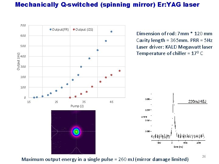
Mechanically Q-switched (spinning mirror) Er: YAG laser 700 Output(FR) Output (QS) Dimension of rod: 7 mm * 120 mm Cavity length = 365 mm. PRR = 5 Hz Laser driver: KALD Megawatt laser Temperature of chiller = 170 C 600 Output (m. J) 500 400 300 200 100 0 15 25 35 Pump (J) 45 Maximum output energy in a single pulse = 260 m. J (mirror damage limited) 26
Summary and outlook q Optically pumped high pressure CO 2 offers potential for compact, efficient generation/amplification of high power, picosecond pulses at 10 µm q Experimental demonstrations of low pressure lasing in CO 2 pumped by an Fe 2+: Zn. Se laser indicate high optical- optical conversion efficiencies are possible q Scaling to higher pressure requires better understanding of physics behind CO 2 lasing (self-focusing of pump, CO 2 relaxation processes) and/or more energetic pump source q Plan to submit DOE proposal to demonstrate and optimize a short pulse OP lasers, focusing on a shorter pulse length down to 300 fs, and power scaling. 27
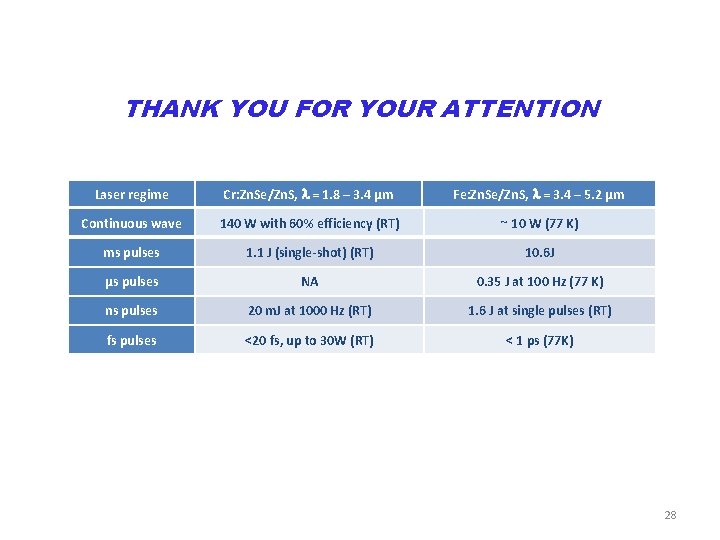
THANK YOU FOR YOUR ATTENTION Laser regime Cr: Zn. Se/Zn. S, = 1. 8 – 3. 4 µm Fe: Zn. Se/Zn. S, = 3. 4 – 5. 2 µm Continuous wave 140 W with 60% efficiency (RT) ~ 10 W (77 K) ms pulses 1. 1 J (single-shot) (RT) 10. 6 J µs pulses NA 0. 35 J at 100 Hz (77 K) ns pulses 20 m. J at 1000 Hz (RT) 1. 6 J at single pulses (RT) fs pulses <20 fs, up to 30 W (RT) < 1 ps (77 K) 28
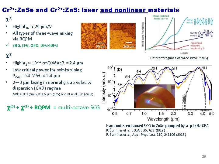
Cr 2+: Zn. Se and Cr 2+: Zn. S: laser and nonlinear materials (2) • • High d 36 20 pm/V All types of three-wave mixing via RQPM ü SHG, SFG, OPO, DFG/IDFG (3) • • • High n 2 at = 2. 4 µm Low critical power for self-focusing PCrit = 0. 4 MW at 2. 4 µm 2— 3 µm lasing in normal group velocity dispersion (GVD) regime 10 -14 cm 2/W Different regimes of three-wave mixing GVD 0 fs 2/mm at 3. 6 µm (Zn. S) and at 4. 81 µm (Zn. Se) (3) + (2) + RQPM = multi-octave SCG Harmonics-enhanced SCG in Zn. Se pumped by a µJ k. Hz CPA R. Šuminas et al. , JOSA B 36, A 22 (2019) R. Šuminas et al. , Appl. Phys. Lett. 110, 241106 (2017) 29
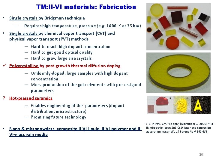
TM: II-VI materials: Fabrication • Single crystals by Bridgman technique — • Requires high temperature, pressure (e. g. 1600 K at 75 bar) Single crystals by chemical vapor transport (CVT) and physical vapor transport (PVT) methods — Hard to reach high dopant concentration — Hard to get good optical quality — Hard to grow large size crystals ü Polycrystalline by post-growth thermal diffusion doping — Uniformly-doped, large samples with high dopant concentration — Mass-production of the gain elements with pre-assigned parameters ? Hot-pressed ceramics — Enables engineering of the parameters (dopant distribution, microstructure) — Promising future technology • Nano & micropowders, composite II-VI-liquid, II-VI-polymer and IIVI-glass gain media S. B. Mirov, V. V. Fedorov, (November 1, 2005) Mid. IR microchip laser: Zn. S: Cr 2+ laser and saturation absorption material”, US Patent No 6, 960, 486 30
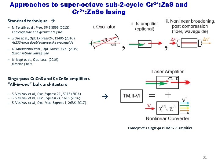
Approaches to super-octave sub-2 -cycle Cr 2+: Zn. S and Cr 2+: Zn. Se lasing Standard technique → ‒ N. Tolstik et al. , Proc. SPIE 8599 (2013) Chalcogenide and germanate fiber ‒ S. Xie et al. , Opt. Express 24, 12406 (2016) As 2 S 3 -silica double-nanospike waveguide ‒ D. Martyshkin et al. , Opt. Mater. Exp. (2019) Silicon nitride waveguide ‒ N. Nagl et al. , Opt. Lett. (2019) fluoride fibers Singe-pass Cr: Zn. S and Cr: Zn. Se amplifiers “All-in-one” bulk architecture ‒ S. Vasilyev et al. , Opt. Express 22 , 5118 (2014) ‒ S. Vasilyev et al. , Opt. Express 24, 1616 (2016) ‒ S. Vasilyev et al. , Opt. Mat. Express 7, 2636 (2017) → Concept of a single-pass TM: II-VI amplifier 31
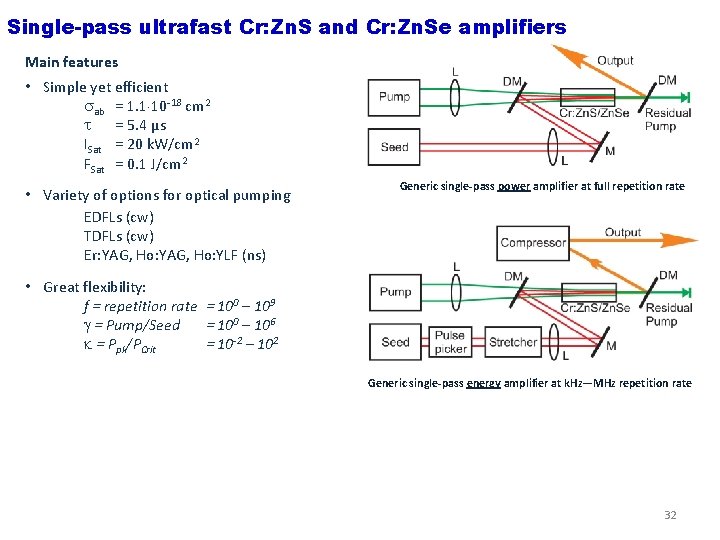
Single-pass ultrafast Cr: Zn. S and Cr: Zn. Se amplifiers Main features • Simple yet efficient ab = 1. 1 10 -18 cm 2 = 5. 4 µs ISat = 20 k. W/cm 2 FSat = 0. 1 J/cm 2 • Variety of options for optical pumping EDFLs (cw) TDFLs (cw) Er: YAG, Ho: YLF (ns) Generic single-pass power amplifier at full repetition rate • Great flexibility: f = repetition rate = 100 – 109 = Pump/Seed = 100 – 106 = Ppk/PCrit = 10 -2 – 102 Generic single-pass energy amplifier at k. Hz—MHz repetition rate 32
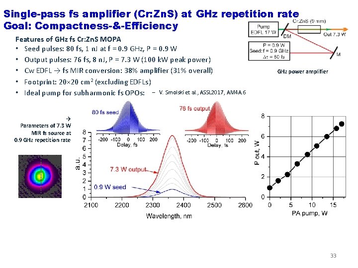
Single-pass fs amplifier (Cr: Zn. S) at GHz repetition rate Goal: Compactness-&-Efficiency Features of GHz fs Cr: Zn. S MOPA • Seed pulses: 80 fs, 1 n. J at f = 0. 9 GHz, P = 0. 9 W • Output pulses: 76 fs, 8 n. J, P = 7. 3 W (100 k. W peak power) • Cw EDFL → fs MIR conversion: 38% amplifier (31% overall) • Footprint: 20× 20 cm 2 (excluding EDFLs) • Ideal pump for subharmonic fs OPOs: ‒ V. Smolski et al. , ASSL 2017, AM 4 A. 6 GHz power amplifier → Parameters of 7. 3 W MIR fs source at 0. 9 GHz repetition rate 33
Summary and outlook q Middle-IR lasers based on Cr and Fe doped Zn. S and Zn. Se have come of age • Advances in fabrication of ceramic/polycrystalline laser materials • Availability of cost efficient fiber pump lasers at 1. 5— 2 µm • Advances in laser design and thermal management q Important milestones have been reached • 0. 15 k. W level in cw laser power • >J-level energy q Ultrafast Cr 2+-based lasers and amplifiers provide unique combination of parameters in the spectral range 2— 3 µm • Short Pulses: 2— 3 optical cycles (Outlook sub-2 cycle) • High power: in excess of 27 W (Outlook 100 W) • Very high efficiency : 20 – 40 % conversion from cw EDFL and TDFL to fs MIR 34
Summary and outlook q Cr 2+: Zn. S(Se)—Ga. Se tandems enable generation of 5 -octave (0. 4— 20 µm) continua • First bulk, multi-octave continuum at full 80 MHz repetition rate of a fs oscillator • First implementations of new SCG regimes: Harmonics-enhanced supercontinuum generation in RQMP media IDFG-enhanced supercontinuum generation • Direct f. CEO measurements confirm high spatio-temporal coherence of the continuum q Future TW-class Cr, Fe: Zn. S/Zn. Se and Fe: Zn. S/Zn. Se/Zn. Cd. Te amplifiers at 2 – 8 µm q Future electrically pumped TM: II-VI lasers q Increasing interest from various fields • Spectroscopy and sensing • Processing of materials • Medicine-, defense-related applications, etc. • Strong field physics and nonlinear optics, atto-science 35
- Slides: 35