From Auto CAD to Arc View From Auto


 n Save Auto. CAD drawing w As Campus. DWG")


- Slides: 75
From Auto. CAD to Arc. View
From Auto. CAD to Arcview Purpose n Display a site plan drawn in Auto. Cad on a view drawn in Arc. View Given n Campus site plan drawing based on an assumed origin with survey monuments Arc. View view of the United States in geographic coordinates (degrees) Data sets of wetlands and aquifers in other coordinate systems
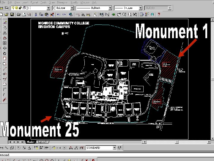
From Auto. CAD Given: n n n Campus plan with assumed coordinate system Units are in feet Property line survey monuments are shown in New York State plane coordinate system w Monument 1 n Northing 1, 129, 290. 14 Easting 761, 886. 75 w Monument 25 n Northing 1, 133, 064. 73 Easting 758, 358. 74
From Auto. CAD Assumed: n n Campus map was in 1927 state plane coordinates, New York west Monument northings and eastings are in feet
From Auto. CAD Procedure n Use Auto. CAD world coordinate system w Because Auto. CAD user coordinate system did not translate to Arc. View n Use Auto. CAD “move command” w to move all the drawing elements from assumed coordinates to northing and easting coordinates n Use Auto. CAD “rotate command” w To align drawing to true north and south
From Auto. CAD Procedure (continued) n Save Auto. CAD drawing w As Campus. DWG n Create and save a “world file” for Arc. View to use when creating a theme of the Campus map w Open text editor (notepad. exe) w Anticipate bringing the campus map into an Arc. View view already projected to State Plane 1927 New York, west
From Auto. CAD n If the Campus map is on New York west and Arc. View view is projected to New York west then the text file that coordinates between the two is: w 0, 0 w This one line text file should be saved in the same folder as the Auto. CAD drawing w This file should have the same name as the Auto. CAD drawing and a. wld extension w In our example: Campus. wld
In general terms Select a point with known coordinates in both the Auto. CAD drawing and the new “shape file”. The. WLD (world file) will tell Arcview which point to line up. n n The concept: X 1, Y 1= X 2, Y 2 The syntax: X 1, Y 1 X 2, Y 2 Auto. CAD coordinates space State plane coordinates “new Shape file” coordinates
Coordinate Transformation. WLD file holds the transformation information. WLD file is a text file. WLD file is in the same folder as the. DWG file. WLD file format is: n X, Y<space>new. X, new. Y
Example Locate the Auto. CAD drawing of the campus of Monroe Community College in Monroe County, New York
from Auto. CAD
from Auto. CAD Check assumed coordinate system origin
from Auto. CAD 0, 0 is in the lower left corner of the map
from Auto. CAD Zoom in on monument 25 in lower left
from Auto. CAD Object snap helps to get right on the point
from Auto. CAD Use zoom extents to find the drawing after the move
from Auto. CAD Check coordinates to show move
from Auto. CAD Rotate using reference angle North straight up
from Auto. CAD Zoom in to monument 1 for reference angle end point
Pick monument 1 as second point of reference angle Type in coordinates of monument 1 as the “new angle”
from Auto. CAD Zoom extents to find drawing rotated to true north Save
WARNING For many Arc. View users the most difficult aspect of working with data in a GIS environment is the concept of map projections.
theme to geographic coordinates
From Auto. CAD to Arc. View The Auto. CAD drawing n n Is in state plane coordinates. wld file is in the same folder Arc. View n n Placed in state plane projection Campus. dwg inported into Arc. View view Campus saved as a theme Theme projected to geographic coordinates
theme to geographic coordinates
theme to geographic coordinates Turn on extentions
theme to geographic coordinates For CAD Reader
theme to geographic coordinates And Projection Utility Wizard
theme to geographic coordinates
theme to geographic coordinates Start a new view
Theme to geographic coordinates Add the drawing as a theme
theme to geographic coordinates
Save theme As a shape file Convert the saved shape file n n From state plane coordinates To geographic coordinates
theme to geographic coordinates Start the projection utility from the “File” on the menu bar
theme to geographic coordinates Sometimes it is hard to remember where the shape file was saved
theme to geographic coordinates Specify the state plane coordinates
theme to geographic coordinates Yes to save the coordinate info
theme to geographic coordinates For the new system, click the geographic radio button
theme to geographic coordinates Select no
theme to geographic coordinates Make a note of the file location Pick a better file name
theme to geographic coordinates
theme to geographic coordinates Display the new theme over top of the old theme
theme to geographic coordinates Or the new theme can be added the regular way
From Auto. CAD to Arcview To demonstrate n n Display Arcview of the counties of United States Add the campus theme
Arc. View Add theme of campus on geographic coordinates
Arc. View Select campus map in geographic coordinates
Arcview Theme needs to be clicked on
Arcview Campus in geographic coordinates Next add other themes in geographic coordinates
Arcview Check the values of the geographic coordinates
Arcview Add the quadrangle wetlands, NY state aquifers, 50 states, and world themes
Arcview Turn themes on after reordering
Arcview Campus theme should be on top
Arcview The new world order
Arcview Click themes on n Notice wetlands indicated on campus
Arcview Use the zoom out button
Arcview Aquifers Wetlands quad
Arcview Zoom back
Arcview Zoom back
Arcview Zoom back
Arcview Zoom back
Arcview Change the coordinate system from geographic properties
Arcview projection
Arcview Change projections
Arcview Scroll down
Arcview Scroll down to the world from space
Arcview Nice view, and it still contains the campus map
Arcview Zoom way in
Arcview And check the coordinaates
Arcview Change units to feet
Arcview And change coordinates to state plane 1927 New York, west
Arcview Check coordinates Change units from meters to feet
Auto. CAD to Arc. View Campus drawing in Arc. View
If none of this works. . Check to see if you turned on the extensions
The end