
FREQUENCY SELECTIVE CIRCUITS Osman Parlaktuna Osmangazi University Eskisehir

- Slides: 30
FREQUENCY SELECTIVE CIRCUITS Osman Parlaktuna Osmangazi University Eskisehir, TURKEY www. ogu. edu. tr/~oparlak
FILTERS n n n Varying the frequency of a sinusoidal source alters the impedance of inductors and capacitors. The careful choice of circuit elements and their connections enables us to construct circuits that pass a desired range of frequencies. Such circuits are called frequency selective circuits or filters. The frequency range that frequencies allowed to pass from the input to the output of the circuit is called the passband. Frequencies not in a circuit’s passband are in its stopband. Circuit Analysis II Spring 2005 Osman Parlaktuna
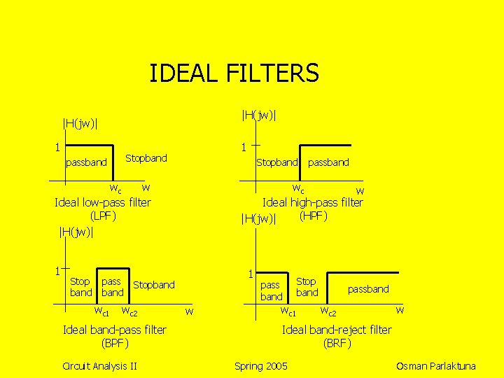
IDEAL FILTERS |H(jw)| 1 1 Stopband passband Stopband wc w Ideal low-pass filter (LPF) |H(jw)| 1 Stop band pass band wc 1 wc w Ideal high-pass filter (HPF) |H(jw)| 1 Stopband wc 2 Ideal band-pass filter (BPF) Circuit Analysis II passband w pass band wc 1 Stop band passband wc 2 w Ideal band-reject filter (BRF) Spring 2005 Osman Parlaktuna
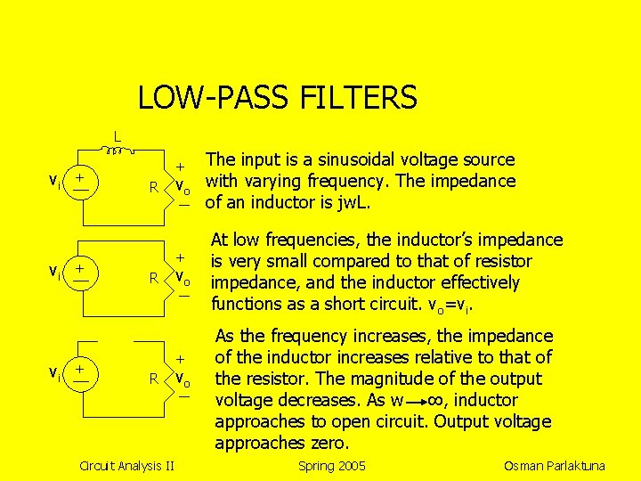
LOW-PASS FILTERS L vi vi vi + + R vo + R Circuit Analysis II vo The input is a sinusoidal voltage source with varying frequency. The impedance of an inductor is jw. L. At low frequencies, the inductor’s impedance is very small compared to that of resistor impedance, and the inductor effectively functions as a short circuit. vo=vi. As the frequency increases, the impedance of the inductor increases relative to that of the resistor. The magnitude of the output voltage decreases. As w ∞, inductor approaches to open circuit. Output voltage approaches zero. Spring 2005 Osman Parlaktuna
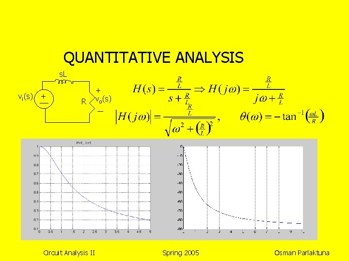
QUANTITATIVE ANALYSIS s. L vi(s) + R Circuit Analysis II + vo(s) Spring 2005 Osman Parlaktuna
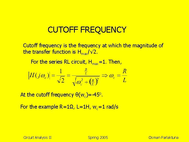
CUTOFF FREQUENCY Cutoff frequency is the frequency at which the magnitude of the transfer function is Hmax/√ 2. For the series RL circuit, Hmax=1. Then, At the cutoff frequency θ(wc)=-450. For the example R=1Ω, L=1 H, wc=1 rad/s Circuit Analysis II Spring 2005 Osman Parlaktuna
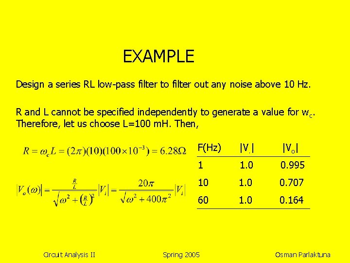
EXAMPLE Design a series RL low-pass filter to filter out any noise above 10 Hz. R and L cannot be specified independently to generate a value for w c. Therefore, let us choose L=100 m. H. Then, Circuit Analysis II F(Hz) |V. | |Vo| 1 1. 0 0. 995 10 1. 0 0. 707 60 1. 0 0. 164 Spring 2005 Osman Parlaktuna
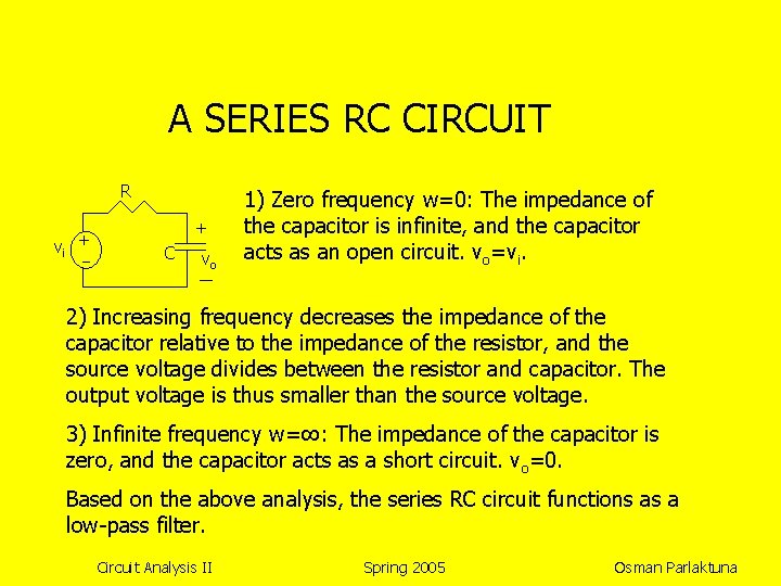
A SERIES RC CIRCUIT R vi + + C vo 1) Zero frequency w=0: The impedance of the capacitor is infinite, and the capacitor acts as an open circuit. vo=vi. 2) Increasing frequency decreases the impedance of the capacitor relative to the impedance of the resistor, and the source voltage divides between the resistor and capacitor. The output voltage is thus smaller than the source voltage. 3) Infinite frequency w=∞: The impedance of the capacitor is zero, and the capacitor acts as a short circuit. vo=0. Based on the above analysis, the series RC circuit functions as a low-pass filter. Circuit Analysis II Spring 2005 Osman Parlaktuna
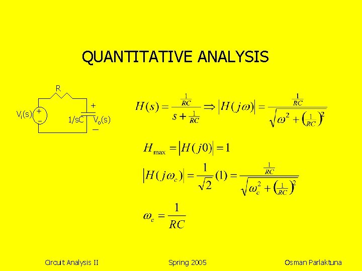
QUANTITATIVE ANALYSIS R Vi(s) + + 1/s. C Vo(s) Circuit Analysis II Spring 2005 Osman Parlaktuna
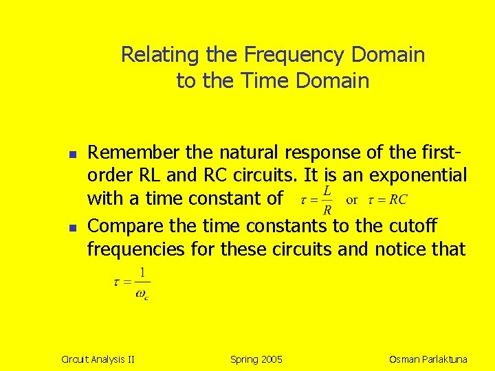
Relating the Frequency Domain to the Time Domain n n Remember the natural response of the firstorder RL and RC circuits. It is an exponential with a time constant of Compare the time constants to the cutoff frequencies for these circuits and notice that Circuit Analysis II Spring 2005 Osman Parlaktuna
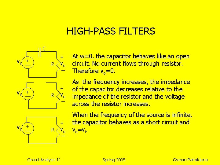
HIGH-PASS FILTERS C vi vi vi + + R vo vo As the frequency increases, the impedance of the capacitor decreases relative to the impedance of the resistor and the voltage across the resistor increases. + When the frequency of the source is infinite, the capacitor behaves as a short circuit and vo=vi. + R R Circuit Analysis II At w=0, the capacitor behaves like an open circuit. No current flows through resistor. Therefore vo=0. vo Spring 2005 Osman Parlaktuna
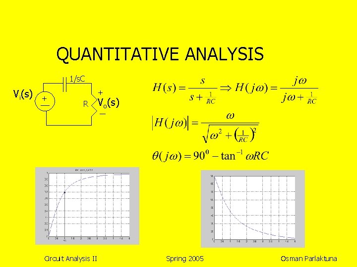
QUANTITATIVE ANALYSIS 1/s. C Vi(s) + + R Circuit Analysis II Vo(s) Spring 2005 Osman Parlaktuna
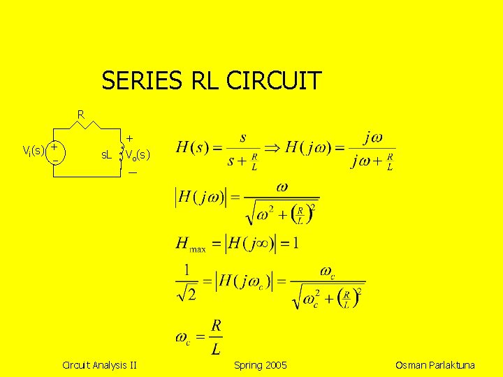
SERIES RL CIRCUIT R Vi(s) + s. L + Vo(s) Circuit Analysis II Spring 2005 Osman Parlaktuna
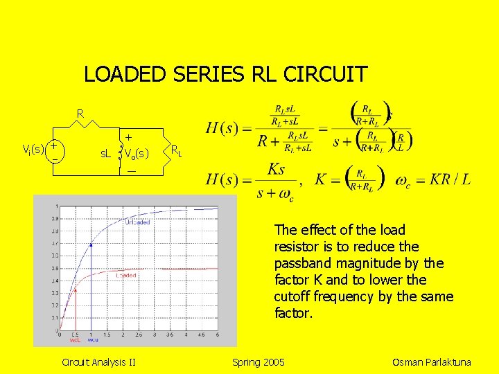
LOADED SERIES RL CIRCUIT R Vi(s) + s. L + Vo(s) RL The effect of the load resistor is to reduce the passband magnitude by the factor K and to lower the cutoff frequency by the same factor. Circuit Analysis II Spring 2005 Osman Parlaktuna
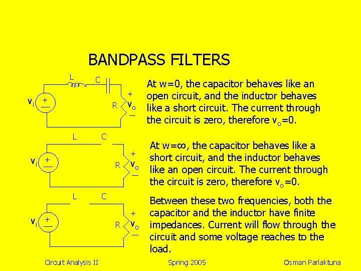
BANDPASS FILTERS L vi C + + R L vi vo + Circuit Analysis II vo C + R vo At w=0, the capacitor behaves like an open circuit, and the inductor behaves like a short circuit. The current through the circuit is zero, therefore vo=0. At w=∞, the capacitor behaves like a short circuit, and the inductor behaves like an open circuit. The current through the circuit is zero, therefore vo=0. Between these two frequencies, both the capacitor and the inductor have finite impedances. Current will flow through the circuit and some voltage reaches to the load. Spring 2005 Osman Parlaktuna
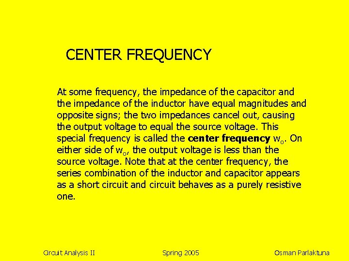
CENTER FREQUENCY At some frequency, the impedance of the capacitor and the impedance of the inductor have equal magnitudes and opposite signs; the two impedances cancel out, causing the output voltage to equal the source voltage. This special frequency is called the center frequency wo. On either side of wo, the output voltage is less than the source voltage. Note that at the center frequency, the series combination of the inductor and capacitor appears as a short circuit and circuit behaves as a purely resistive one. Circuit Analysis II Spring 2005 Osman Parlaktuna
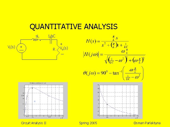
QUANTITATIVE ANALYSIS s. L Vi(s) + Circuit Analysis II 1/s. C R + Vo(s) Spring 2005 Osman Parlaktuna
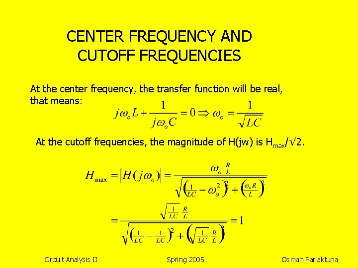
CENTER FREQUENCY AND CUTOFF FREQUENCIES At the center frequency, the transfer function will be real, that means: At the cutoff frequencies, the magnitude of H(jw) is Hmax/√ 2. Circuit Analysis II Spring 2005 Osman Parlaktuna
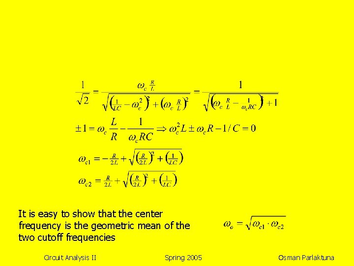
It is easy to show that the center frequency is the geometric mean of the two cutoff frequencies Circuit Analysis II Spring 2005 Osman Parlaktuna
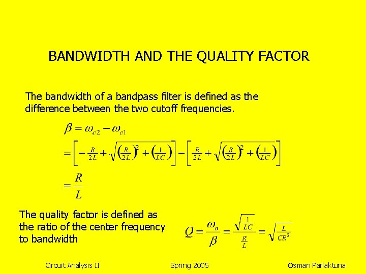
BANDWIDTH AND THE QUALITY FACTOR The bandwidth of a bandpass filter is defined as the difference between the two cutoff frequencies. The quality factor is defined as the ratio of the center frequency to bandwidth Circuit Analysis II Spring 2005 Osman Parlaktuna
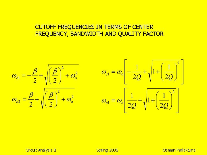
CUTOFF FREQUENCIES IN TERMS OF CENTER FREQUENCY, BANDWIDTH AND QUALITY FACTOR Circuit Analysis II Spring 2005 Osman Parlaktuna
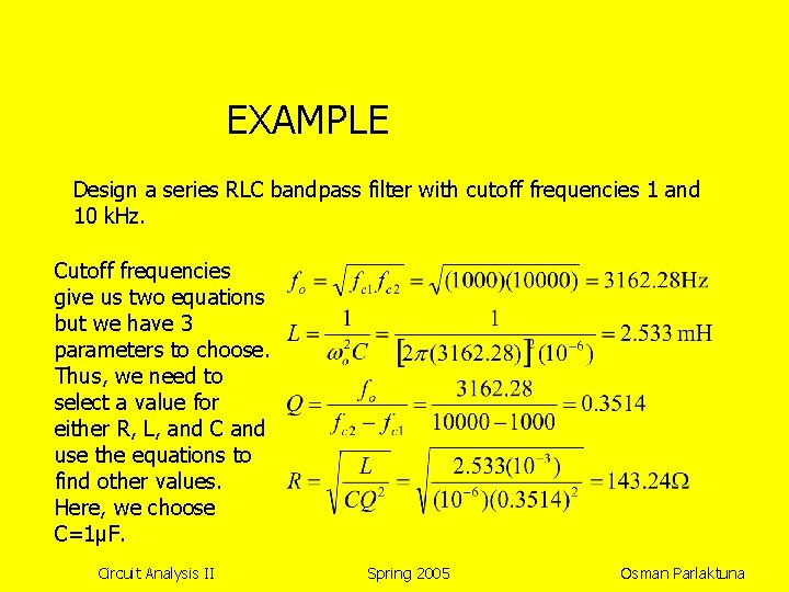
EXAMPLE Design a series RLC bandpass filter with cutoff frequencies 1 and 10 k. Hz. Cutoff frequencies give us two equations but we have 3 parameters to choose. Thus, we need to select a value for either R, L, and C and use the equations to find other values. Here, we choose C=1μF. Circuit Analysis II Spring 2005 Osman Parlaktuna
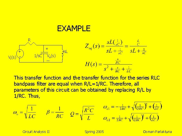
EXAMPLE R + Vi(s) + 1/s. C Vo(s) s. L This transfer function and the transfer function for the series RLC bandpass filter are equal when R/L=1/RC. Therefore, all parameters of this circuit can be obtained by replacing R/L by 1/RC. Thus, Circuit Analysis II Spring 2005 Osman Parlaktuna
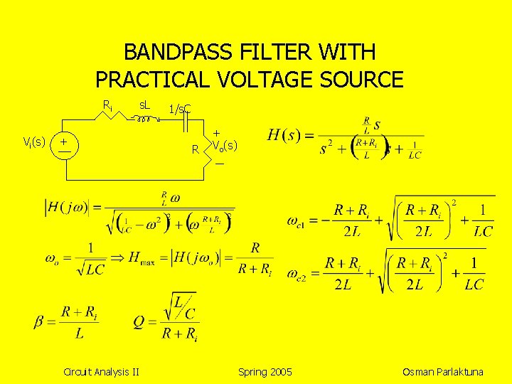
BANDPASS FILTER WITH PRACTICAL VOLTAGE SOURCE Ri Vi(s) + Circuit Analysis II s. L 1/s. C R + Vo(s) Spring 2005 Osman Parlaktuna
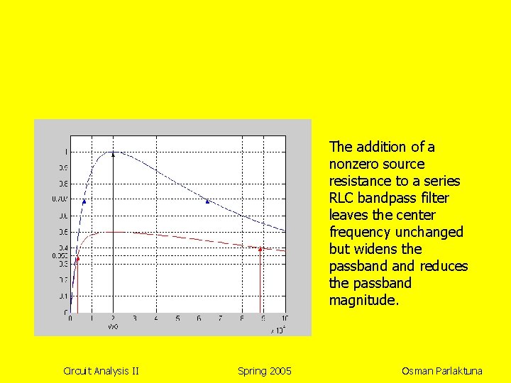
The addition of a nonzero source resistance to a series RLC bandpass filter leaves the center frequency unchanged but widens the passband reduces the passband magnitude. Circuit Analysis II Spring 2005 Osman Parlaktuna
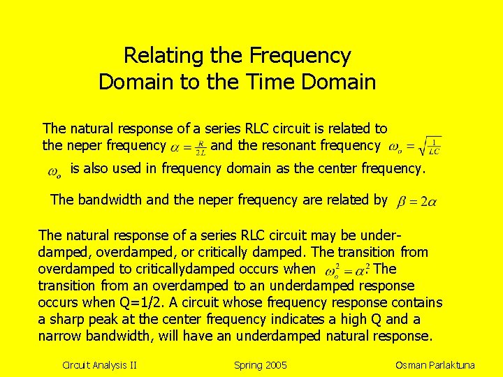
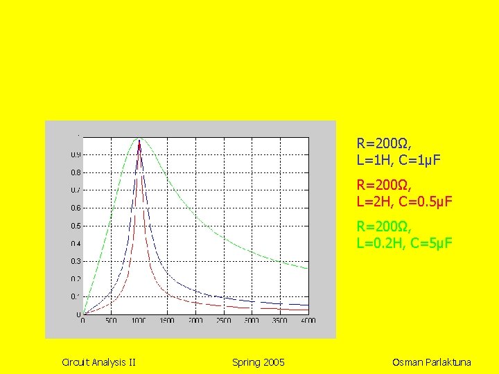
Relating the Frequency Domain to the Time Domain The natural response of a series RLC circuit is related to the neper frequency and the resonant frequency is also used in frequency domain as the center frequency. The bandwidth and the neper frequency are related by The natural response of a series RLC circuit may be underdamped, overdamped, or critically damped. The transition from overdamped to criticallydamped occurs when. The transition from an overdamped to an underdamped response occurs when Q=1/2. A circuit whose frequency response contains a sharp peak at the center frequency indicates a high Q and a narrow bandwidth, will have an underdamped natural response. Circuit Analysis II Spring 2005 Osman Parlaktuna
R=200Ω, L=1 H, C=1μF R=200Ω, L=2 H, C=0. 5μF R=200Ω, L=0. 2 H, C=5μF Circuit Analysis II Spring 2005 Osman Parlaktuna
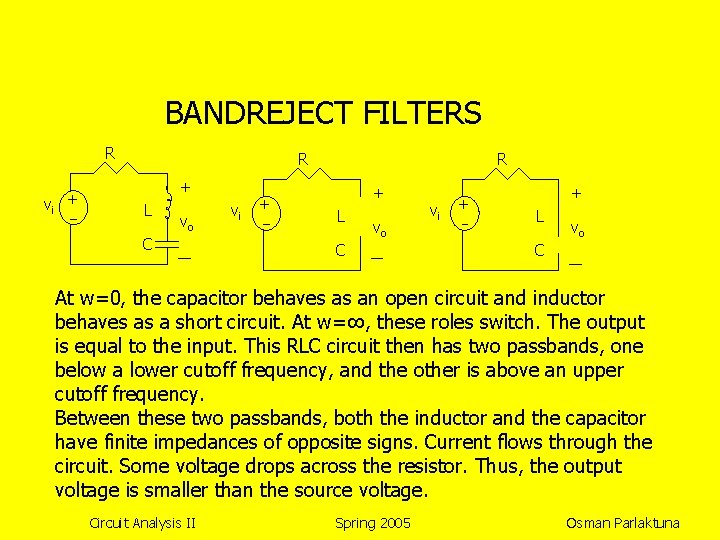
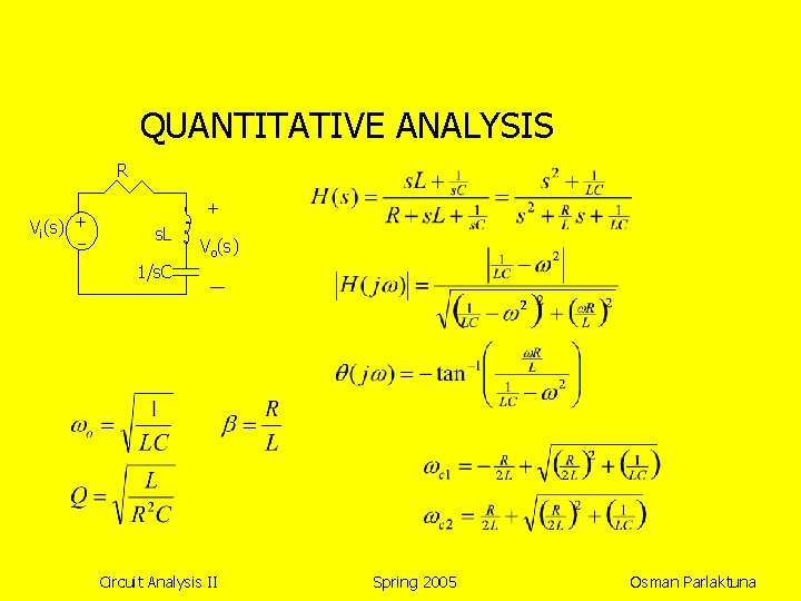
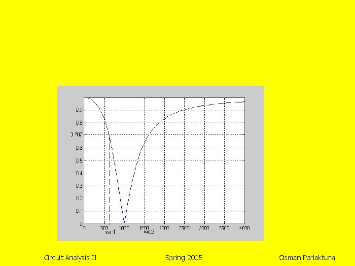
BANDREJECT FILTERS R vi + R + L vo C vi + + L vo C At w=0, the capacitor behaves as an open circuit and inductor behaves as a short circuit. At w=∞, these roles switch. The output is equal to the input. This RLC circuit then has two passbands, one below a lower cutoff frequency, and the other is above an upper cutoff frequency. Between these two passbands, both the inductor and the capacitor have finite impedances of opposite signs. Current flows through the circuit. Some voltage drops across the resistor. Thus, the output voltage is smaller than the source voltage. Circuit Analysis II Spring 2005 Osman Parlaktuna
QUANTITATIVE ANALYSIS R Vi(s) + + s. L Vo(s) 1/s. C Circuit Analysis II Spring 2005 Osman Parlaktuna
Circuit Analysis II Spring 2005 Osman Parlaktuna