FREQUENCY HOPPING FHSSS In FHSSS the carrier frequency


- Slides: 6

FREQUENCY HOPPING FH-SSS: In FH-SSS, the carrier frequency is changed randomly according to a PN code. FH-SSS is used for mobile civilian and military tactical communications. According to the hop rate ( hop rate is the speed of hopping, which is the number of times the carrier frequency is changed per second), and its relation to the data rate, FH-SSS systems are classified into: -Fast FH-SSS: when each data bit is transmitted by one or more carrier frequencies, i. e when the hop rate is greater than the data rate. -Slow FH-SSS: : when more than one data bits are transmitted by one carrier frequency. i. e when the hop rate is less than the data rate. Note that, spreading of the bandwidth is accomplished by randomly hopping the carrier using N hopping frequencies. The spreading bandwidth is Brf. SSS = N. ∆f. The channel spacing ∆f is determined by the bandwidth of the information. Channel spacing ∆f Brf. SSS f

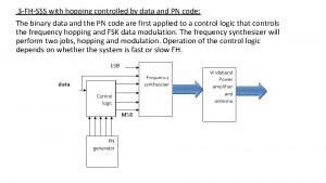
According to the modulation of carrier by data and address code, the following FH systems are given: 1 -FH-SSS with conventional modulation: Here, the frequency hopper is controlled by a PN code, while the data signal (may be analog or digital) modulates the hopping carrier. fo = m. fr, where m is the random address set by the k-bit PN code generator 2 k > m > 0 fr K bit fo data Analog information At the Tx side, the PN code generator is driven by a clock that determines the hop rate. The k-bit parallel outputs of the PN generator are used to control the instantaneous carrier frequency fo.

The reference frequency fr is obtained from a high stable crystal oscillator. This fo is then used in any conventional modulator (may be analog or digital) to produce the FH signal. information flocal K bit At the Rx side, there is an identical PN generator controlling the frequency synthesizer. The local frequency flocal hops synchronously with that at the Tx with a constant IF frequency between them, i. e:

f. IF= fo - flocal (note: both fo and flocal hops randomly but the difference between them is kept constant as the IF frequency). Note: Suggested Seminar (report)on Frequency Synthesizers(types, operations, . . etc): 2 -FH system with single channel data modulation: First, the carrier is modulated by a digital information signal and then the modulated carrier hops according to the PN code by a mixer & frequency synthesizer ( up conversion to fo), i. e, the data is first modulated then hopped. mix er data fc fo

Hopping pattern hopping clock 1 2 f 4 3 f 3 4 f 6 5 f 1 6 f 5 f f 1 f 2 f 3 f 4 f 5 f 6 Hopping pattern f 2 f 4 f 3 f 6 f 1 f 5 Th 2 Th 3 Th 4 Th 5 Th 6 Th f

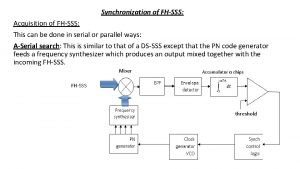
If synchronization is achieved between the Tx and Rx PN generators, then the mixer output set at a certain f. IF = fo-flocal is applied to the IF amplifier with a bandwidth equals the bandwidth of the PSK signal. mixer data

