FREIGHT STOCK 1 Bearing 2 Bearing Adapter 4

FREIGHT STOCK

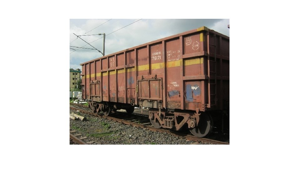

1. Bearing 2. Bearing Adapter 4. Side Frame 5. Load Bearing Springs 7. Friction Shoe Wedge 8. Spring Plank 10. Side Bearer 11. Pivot 3. Elastomeric Pad 6. Snubber Springs 9. Bolster 12. Brake Beam

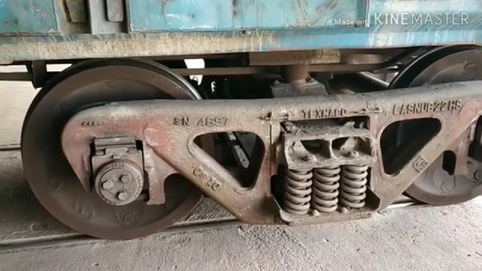
The salient features of CASNUB Bogie: - SN Feature 1 Gauge 2 Axle load 3 Wheel diameter 4 5 Wheel base Bearing 6 Description 1676 mm 20. 3 t, However all bogies except CASNUB 22 HS can be upgraded up to 22. 9 t 1000 mm (New) 906 mm (Condemn) for all types. 2000 mm (+/- 5 mm) Standard AAR Tapered Cartridge Bearing Class E suitable for 144. 5 x 277. 8 mm wide jaws or narrow jaw as per different variants. Distance between 2260 mm journal centres

7 Distance between side bearers 1474 mm 8 Type of side bearers (Metal bonded rubber pad, housed inside bearer housing)/PU Type CASNUB 22 HS: Spring loaded constant contact type/PU Type side bearer. 9 Type of pivot CASNUB 22 W: - IRS Type Top Pivot - RDSO Drg. No. W/BE-601, Bottom Pivot– RDSO Drg. No. W/BE-602 or similar matching profile integrally cast with bolster. CASNUB 22 W(M), 22 NLB, 22 HS : -Spherical Type to RDSO Drg. No. WD-85079 -S/2

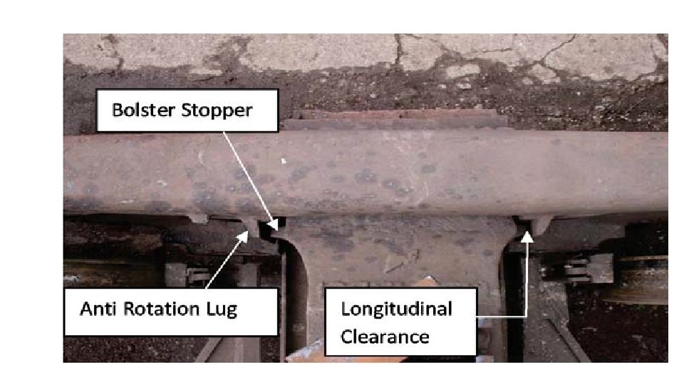
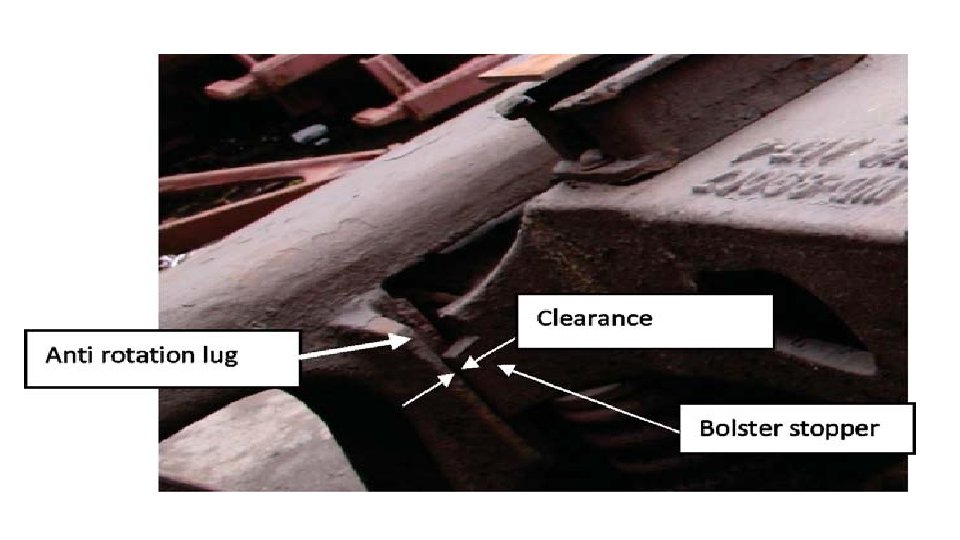
10 11 Anti rotation lugs have been provided between bogie features bolster and side frame Suspension details Long travel helical spring

Adapter is to be thoroughly inspected for soundness and wear, Wear at Thrust shoulder , Adapter bore (bearing seat), Adaptor crown lugs , Adapter crown seat, Adapter side lugs and Adapter sides is to be checked by corresponding gauges.

Adapter

Defects in Adapter: • Check adaptor for crack. Twist or distortion, • Check for soundness and wear.
 Elastomeric pads are provided in all versions of CASNUB bogie")
Elastomeric Pad (EM Pad) Elastomeric pads are provided in all versions of CASNUB bogie except CASNUB 22 W. The main purpose of providing elastomeric pad is to reduce wheel flange wear.
 & WD-95005 -S-1)")
Defects in Elastomeric pads (to 95005 -S/4, Wd-92058 -S/8 (for HS) & WD-95005 -S-1) : • If the top or the bottom plates or intermediate plate show any crack in service. • If any crack of more than 50 mm is developed at any surface of rubber. • If a bond failure giving way more than 40 mm in any direction is developed in service. • If any sign of crushing of rubber is noticed.

SIDE FRAME. Spring Plank

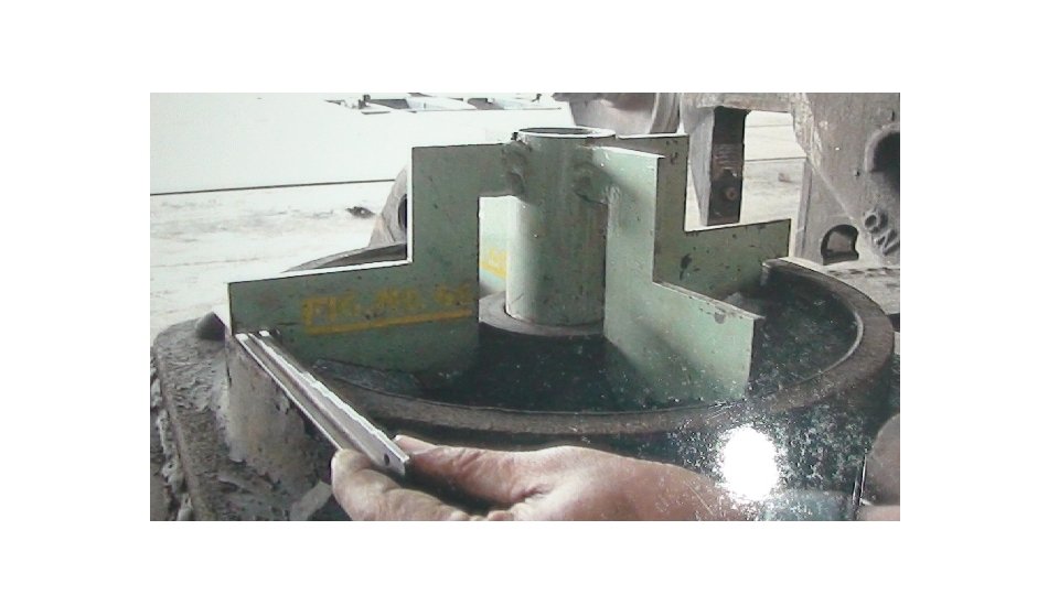
Side Frames with Friction Wear Plates • Side frame column has been provided with 10 mm thick Silico Manganese Steel wear liners to IS: 3885 Pt. -I Gr. IV welded on the columns. • Amount of wear is determined by placing the gauge centrally and inserting shims of appropriate thickness.

• Defects in Side Frame: • Side Frame cracked/broken/bent /corroded. • Side frame friction liner crack/thin. • Pocket liner crack/thin. • Side frame should be checked for its wheel base (distance between centre lines of the jaw openings) and ensure whether the correct button marking is left on the side frame. • Check if there is any difference between the numbers of buttons on the two-side frames of a bogie

• Cast steel floating bolster, rests on nested springs and friction wedge assembly. • Load transmission takes place from the wagon to side frames through bolster

Friction shoe Wedge

Friction shoe or wedge • They are made up of manganese steel fitted on snubber springs. • Vertical surface of the wedge remains in contact with side frame and slope surface in contact with bolster pocket liners. • The dimensions are such that the snubber spring is under compression and in turn presses the wedge upwards. • Increased load results in increased compression resulting into increased magnitude of frictional forces and higher damping.

BOLSTER SLOPE POCKET LINER.

• Bolster pocket has been provided with 8 mm thick Silico Manganese Steel Liners welded with pocket slope. • The liners may be permitted in service up to a thickness of 3 mm. No paint or grease should be applied on the plate. • Excess wear affects the damping mechanism and may cause resonance due to oscillations.

Bottom Plank, Fit Bolts & Rivets • Bottom plank is a member made of solid steel. • It joins two side frames of CASNUB bogie by eight 24 dia rivets and four M 24 fit bolts to keep bogie frame square. • Two cast steel frames are held in square position by bottom plank, fit bolts and rivets. • The helical springs rest on bottom plank. They transfer the load from bolster to side frame. • Bottom plank provides rigidity to bogie frame. • Side frames should always be held in square position otherwise it will cause persistent angular run which may lead to derailment.

Defects in Bolster: • Combined wear of bolster side frame liners and wedges • Condition of bolster pocket slope surface liner. • Bolster cracked/broken Defects in Bottom Plank: • Bottom plank broken, cracked or bent. • Loosening of rivets/bolts, welding failure of spring spigot etc. Lack of squareness of the two cast steel frames

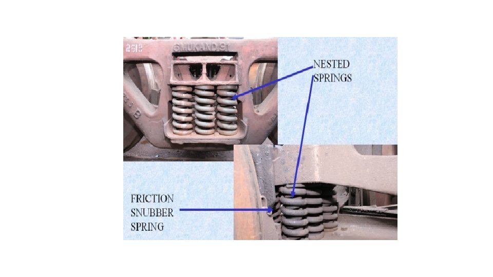
Load Bearing Springs and Snubber Springs • The bogies are fitted with two groups of long travel helical spring nests. • These springs are provided to transfer the load from the bolster to side frame. • During movement bogie passes through track irregularities causing impact load. • Excessive variation in the height of springs within the same group would result in unequal load on springs, resulting in Off-loading, adversely affecting safety. • Spring is condemned on the basis of free height.

Nominal and condemning Free Heights Defects in Springs: • Any spring cracked, broken or twisted. • Pairing of springs should be same. : Type of Bogies Spring Location Free Height (Nominal) (mm) Recommended Free Height(Condemn ing) (mm) All versions Outer Inner except CASNUB 22 Snubber HS 260 262 294 245 247 279 CASNUB 22 Outer Inner HS Snubber 260 243 293 245 228 278

Arrangement of springs.

Centre Pivot Bottom

Centre Pivot Top

Centre Pivot and Side Bearer arrangement • Load from wagon is transferred to bolster through central pivot which is provided at the centre of bolster. • Wagon when negotiating a curve and turnouts bogie rotates about central pivot. • Central pivot provides relative rotation of bogie frame in the horizontal plane of wagon which avoids development of flange forces causing persistent angular run. • Braking and tractive forces are transferred to bogie through pivot pin.
")
Side Bearer (Metal Bonded Rubber Pad)
")
Side Bearer (P. U. Type)

Draw and Buffing Gear: Centre Buffer Coupler
 • Minimum buffer height =")
Maximum buffer height = 1105 mm (In empty condition) • Minimum buffer height = 1030 mm (In loaded condition) • For checking irregular loading: • Maximum permitted buffer height difference with adjacent wagon is 75 mm.

Longitudinal and Lateral Clearance between Side Frame and Bolster

Lateral clearance between Adapter and Side Frame

Bogie Clearances • Lateral and Longitudinal clearances between the Adapter and Side Frame and between Side Frame and Bolster are very important from maintenance point of view (curve negotiability and rail/ wheel wear) as well as for safety (lateral forces and angularity). • Clearances would be worked out considering the Limit of wear of the relevant surfaces. • The Clearances should be measured using a Feeler Gauge.

Longitudinal clearance between Adapter and Side Frame
- Slides: 41