FRACTIONAL ARC TEST GIRDER DESIGN REVIEW PROTOTYPE GIRDER


 locate BPMs with shoulder screws These angles (yellow) just")


 -BDH")

 \"Dipole\" (Inner) Winding \"Quadrupole\" (Outer) Winding")
- Slides: 13
FRACTIONAL ARC TEST GIRDER DESIGN REVIEW
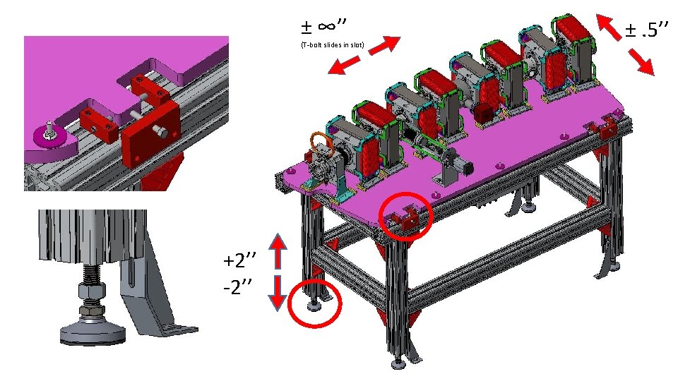
PROTOTYPE GIRDER FRACTIONAL ARC TEST GIRDER Same design except 6’’ longer to accommodate half magnet BDH
±. 25’’ ±. 13’’ Each magnet is supported on three points with three tie-down bolts
Chamber location/mounting These angles (blue) locate BPMs with shoulder screws These angles (yellow) just provide support. Have oversized holes to allow for small misalignment of BPMs Chamber is fixed in location on plate.
Water Tubing Water hoses and beam instrumentation cable feed through here Brass water manifold
Survey/Shipment Workflow • Cornell ships vacuum chamber to BNL. • BNL assembles magnets and chamber to plate. • BNL ships assembly at left to Cornell (un-surveyed). • Cornell receives Rexroth stand assembly from outside vendor. • Cornell joins plate to Rexroth stand. • Cornell does survey and positioning of magnets relative to chamber. • Cornell surveys/positions stand plate into ring.
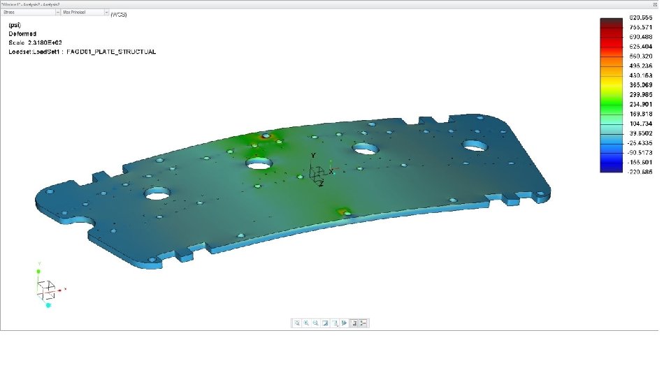
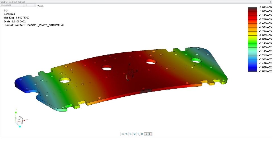
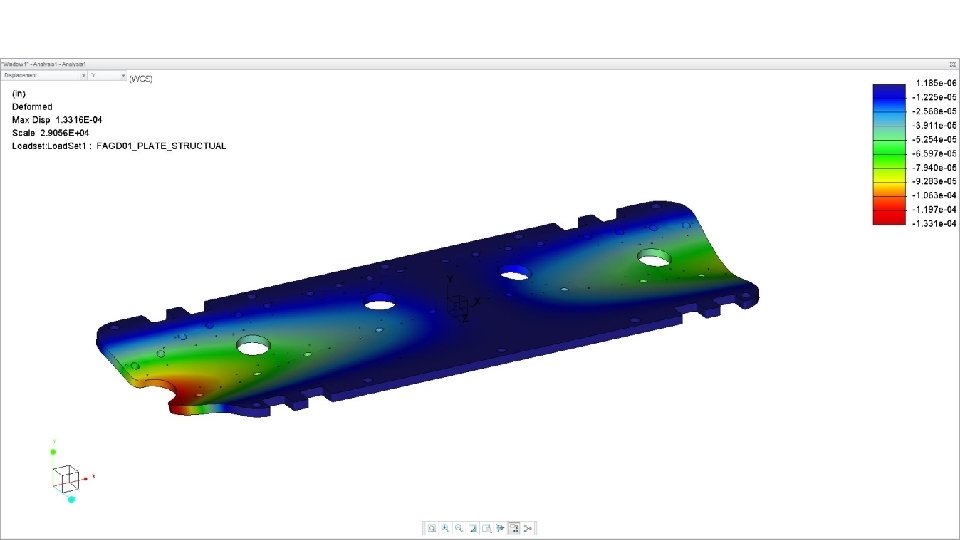
Deflection Analysis -QF, BD = 100 lb. Ea (actual weight 91 lb. ) -BDH = 15 lb. -Supported by Rexroth
Locate mount for FARO survey arm. Used to survey magnets in place.
Corrector Magnets Case 1 Winding (per one coil) "Dipole" (Inner) Winding "Quadrupole" (Outer) Winding Horizontal Corrector Vertical Corrector Case 2 AWG Gauge # of Turns Resistance (Ω) Max Current (A) 14 480 0. 81 2. 29 3 11 463 0. 50 4. 75 3 Case 1: Case 2: Maximum operating currents for separate operation of dipole and quadrupole correctors. Maximum operating current for dipole only operation with both windings in series.