FP 304 DATABASE SYSTEM CHAPTER 2 RELATIONAL DATA

FP 304 DATABASE SYSTEM CHAPTER 2 RELATIONAL DATA MODEL

DEFINITION OF DATABASE Shared collection of logically related data (and a description of this data), designed to meet the information needs of an organization.
 is a database on the relational model developed")
RDBMS Relational Database Management System (RDBMS) is a database on the relational model developed by Dr. E. F. Codd of IBM Research in 1970. A DBMS that manages the relational database.

The model represent data in form of table.

COMPONENTS & CHARACTERISTICS OF RDBMS RELATION Is a table with column and rows A relation(table) consists of unique attributes (column) and tuples (rows) ATTRIBUTE (FIELD) An attribute is named column of relation Used to hold information about the objects to be represented in database RECORD (TUPLE) A record is a row of a relation

COMPONENTS & CHARACTERISTICS OF RDBMS DOMAIN A domain is the set of allowable values for one or more attributes DEGREE The degree of relation is the number of attributes it contains Relationship degree: The number of entities associated with the relationship.

CARDINALITY • The cardinality of relation is the number of rows it contain. • Relationship cardinality: Express the specific number of entity occurrences associated with occurrences of the related entity • In data modelling terms, cardinality is how one table relates to another. ü 1 -1 (1: 1) (one row in table A relates to one row in table. B) ü 1 -Many (1: m) (one row in table A relates to many rows in table. B) üMany-Many (m: n) (Many rows in table A relate to many rows in table B)

COMPONENTS & CHARACTERISTICS OF RDBMS

RELATION INSTANCE Relation: made up of 2 parts: 1. SCHEMA : specifies name of relation, plus name and type of each column E. G. Student(sid: char(10), name: char(20), age: integer, gpa: real, login: char(20)). 2. INSTANCE : a table of values in rows and columns Relation instance is a set of rows (tuples, records) As a set, it is not supposed to have duplicates!

RELATION KEYS There are no duplicate tuples within a relation. Therefore, we need to be able to identify one or more attributes (called relational keys) that uniquely identifies each tuple in a relation. There are several types of relational keys; Primary Key Candidates Key Foreign Key
 in a table that uniquely")
RELATION KEYS PRIMARY KEY is a column (or columns) in a table that uniquely identifies the rows in that table. For example, in the table above, Customer. No is the primary key. The values placed in primary key columns must be unique for each row: no duplicates can be tolerated. In addition, nulls are not allowed in primary key columns.

RELATION KEYS CANDIDATES KEY is a column that meets all of the requirements of a primary key. In other words, it has the potential to be a primary key.

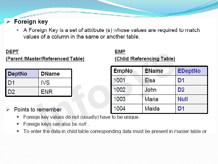
RELATION KEYS FOREIGN KEY are columns that point to primary key columns. So, for example, Order. No is the primary key of the table ORDERS below and Customer. No is a foreign key that points to the primary key in the CUSTOMERS table.

Integrity Rules of constraints or restrictions that apply to all instances of the database. A feature provided by relational database management system (RDBMS), which prevents users or applications from entering inconsistent data. There are 2 types of integrity rules; Entity Integrity Referential Integrity

INTEGRITY RULES ENTITY INTEGRITY No attribute of a primary key can be null. If we allow null for any part of primary key, we are implying that not all the attributes are needed to distinguish between tuples. NULL Null mean that no value has yet been supplied. Null not the same with zero numeric value or text string filled with spaces; zeros and spaces are values A null represent the absence of a value.

INTEGRITY RULES REFERENTIAL INTEGRITY This rule applies to a foreign keys. If a foreign key exist in a relation, either the foreign key value must match a candidate key value of some tuples in its home relation or the foreign key value must be wholly null. A table which has a foreign key referring to its own candidate key is known as self-referencing table.

DATABASE DESIGN TECHNIQUE • ER diagram is widely used in database design – Represent conceptual level of a database system – Describe things and their relationships • ERD is a top-down approach to database design. • ERD consists 3 basic concepts: - Entity - Attribute - Relationship

Entity • Relational database design starts by defining the required entities • Entities are set of object you want to store data about – people (students, customers, employees, etc. ) – places (resorts, cities, countries, restaurants etc. ) – things (products, invoices, movies, paintings, books, buildings, contracts, etc. ) – events (elections, presentations, earthquakes, etc. ) Entity Name • Represented by a rectangular box

Attribute hold values that describe the properties of entities Ø E. g. student entity could have attributes such as name, address, DOB etc. • Each entity has one or more attributes associated with Attribute it. Name • Represented by a ellipse

Type of Attributes Types of Attributes Definition Example Simple attribute Cannot be divided into simpler components Gender of the employee Composite attribute Can be split into components Address of the employee Single valued Can take on only a single value for each entity instance Age of the employee Multi values Can take up many values Skill set of the employee Stored attribute Attribute that need to be stored permanently Date of joining of the employee Derived attribute Attribute that can be calculated based on other attributes Years of the service of the employee

Composite Attribute Street Poscod e Building Designatio n State Address Emp. Name Emp. No DOB EMPLOYEE

MULTI VALUED ATTRIBUTE Street Poscod e Building Designatio n State Address Emp. Name Emp. No DOB EMPLOYEE Skill

STORED & DERIVED ATTRIBUTE Street Poscod e Building Designatio n Emp. Name Emp. No State Address Date. Employe d Years. Employe d EMPLOYEE

ATTRIBUTES OF A RELATIONSHIP Material. ID Vendor. ID VENDOR Vendor. Nam e Supplies Material. Nam e RAW MATERIALS Standard. Cost Vendor. Address Supply. Unit. Pri ce

RELATIONSHIP • Relationship specify the relations among entities from two or more entity sets • Describe a meaningful interaction between entity. • Represented by a diamond Relationship Name

Degree of Relationship • Relationship degree: The number of entities associated with the relationship. Degree: the number of entity types involved One Unary Two Binary Three Ternary

Types of Relationship Degrees 1. Unary Relationship – exist when an association is maintained within a single entity - also known as RECURSIVE RELATIONSHIP COURSE Pre-requisite

Types of Relationship Degrees 2. Binary Relationship – exist when 2 entities are associated PROFESSOR Teaches CLASS

Types of Relationship Degrees 2. Ternary Relationship – exist when 3 entities are associated PROFESSOR Teaches SEMESTER CLASS

RELATIONAL MODEL RELATIONSHIPS Relationship Cardinality: Express the specific number of entity occurrences associated with occurrences of the related entity There are 3 types of relationships; One to One (1: 1) One to Many (1: M) Many to One (M: 1) Many to Many (M: N) Eg; Employee is assigned to parking place (1: 1) Department offers course (1: M) Employee work in department (M: 1) Employee is assigned to project (M: N)
 One occurrence of an entity relates")
RELATIONAL MODEL RELATIONSHIPS ONE TO ONE (1: 1) One occurrence of an entity relates to only one occurrence in another entity A EMPLOYEE B 1 Is_assigned 1 PARKING PLACE
 – One occurrence in an entity")
RELATIONAL MODEL RELATIONSHIPS ONE TO MANY (1: M) – One occurrence in an entity relates to many occurrences in another entity. B 1 B 2 A B 3 DEPARTMENT 1 Offers M COURSE
 many occurrences in an entity relate")
RELATIONAL MODEL RELATIONSHIPS MANY TO ONE (M: 1) many occurrences in an entity relate to one occurrences in another entity B 1 A B 2 B 3 EMPLOYEE M Works in 1 DEPARMENT
 many occurrences in an entity relate")
RELATIONAL MODEL RELATIONSHIPS MANY TO MANY (M: N) many occurrences in an entity relate to many occurrences in another entity B 1 A 1 B 2 A 2 B 3 EMPLOYEE M Is_assigned_to N PROJECT

STEPS IN ER MODELING: q Identify the entities q Find the relationship q Identify the key attributes for every entities q Identify other relevant attributes q Draw complete ER-modelling with all attributes including primary key
 procedural language associated with the relational model.")
RELATIONAL ALGEBRA Relational algebra is a (high-level) procedural language associated with the relational model. Basic operations in relational algebra: Unary Relational Operations: Selection Projection Cartesian product Union Set Difference Intersection Binary Relational Operations Division operations Join

RELATIONAL ALGEBRA
 Selects a subset of rows from relation (horizontal).")
5 BASIC OPERATIONS Selection ( ) Selects a subset of rows from relation (horizontal). Projection ( ) Retains only wanted columns from relation (vertical). Cross-product (x) Allows us to combine two relations. Set-difference (–) Tuples in r 1, but not in r 2. Union ( ) Tuples in r 1 and/or in r 2.

Example Instances R 1 S 1 Boats S 2
 Used to select a subset of the tuples from a")
SELECT operation ( ) Used to select a subset of the tuples from a relation that satisfies a selection condition Symbol -> σ (sigma) Syntax : σ<selection condition>( R )
")
SELECT operation ( )
 Eg 1: Select the STUDENT tuples whose Semester is 3.")
SELECT operation ( ) Eg 1: Select the STUDENT tuples whose Semester is 3. σSem=3(STUDENT) Eg 2: Select the MANAGER tuples whose Salary is greater than RM 25, 000. σSalary>25000(MANAGER) Eg 3: Select the tuples for all SUPERVISOR who either work in IT Department and Salary less than RM 20, 000 per year, or work in HR Department and Salary less than RM 30, 000. σ(Dept=“IT” AND Salary<20000) OR Dept=“HR” AND Salary<30000))(SUPERVISOR)

PROJECT operation Select certain columns from the table and discard the other columns Symbol -> Л (pi) Syntax – Л <attribute list> (R)

PROJECT operation S 2

PROJECT operation Eg 1: List each student’s Regs. No, First Name and Last Name. ЛRegs. No, Fname, Lname(STUDENT) Eg 2: List IDNum, Name and Age of all supervisors who work in IT department. ЛIDNum, Name, Age (σDept=“IT”(SUPERVISOR))

UNION operation UNION compares tuples in two relations and create a new relation that contains some of the tuples from each of the input relations. Symbol -> υ (cup) R υ S

UNION operation S 1 S 2

UNION operation Eg 1: List all IDNum where there is either a Manager or Supervisor for IT Department. ЛIDNum(σDept=“IT”(MANAGER)) υ ЛIDNum(σDept=“IT”(SUPERVISOR)) Eg 2: List Regs. No for students those register at Department and Hostel. ЛRegs. No(DEPARTMENT) υ ЛRegs. No(HOSTEL)

CROSS PRODUCT operation • Defines a relation that is the concatenation of every tuple of relation R with every tuple of relation S. Denoted by X R X S

CROSS PRODUCT operation R 1 X S 1

CARTESIAN PRODUCT operation Eg 1: List the Regs. No, Name and NRIC of all students who registred Course. ID, Course. Name for course. ЛRegs. No, Name, NRIC(Student) X (Л Regs. No, Course. ID, Course. Name(Course))

INTERSECTION operation Defines a relation consisting of the set of all tuples that are in both R and S. Symbol -> ∩ (cap) R ∩ S

INTERSECTION operation S 1 S 2

INTERSECTION operation Eg 1: List Regs. No for students those having register at both Department and Hostel. ЛRegs. No(DEPARTMENT) ∩ ЛRegs. No(HOSTEL)

SET DIFFERENCE operation Defines a relation consisting of the tuples that are in relation R, but not in S. Symbol -> - (minus) R - S

SET DIFFERENCE operation S 1 S 2 c S 2 – S 1

SET DIFFERENCE operation Eg 1: List Regs. No for students those register at Department but no at Hostel. ЛRegs. No(σcourse=“DNS 3 A”(DEPARTMENT)) – ЛRegs. No(σcourse=“DNS 3 A”(HOSTEL))

JOIN operation Compute R X S Select rows where attributes that appear in both relations have equal values Project all unique atttributes and one copy of each of the common ones.

NATURAL JOIN operation R 1 c S 1

Natural Join The tuples in the resulting relation are obtained by combining tuples in the operands with equal values on the common attributes. The common attributes often form a key of one of the operands (remember: references are realized by means of foreign keys, and we join in order to follow references)

OUTER JOIN “Pads With Nulls” A variant of the join, to keep all pieces of information from the operands. Three Variants : Left – only tuples of the left operand are padded. Right – only tuples of the right operand are padded. Full – tuples of both operands are padded

R 1 Employee Department Smith Sales Black Production White Production R 2 Department Head Production Mori Purchasing Brown

OUTER LEFT JOIN R 1 LEFT R 2 EMPLOYEE DEPARTMENT HEAD Smith Sales Null Black Production Mori White Production Mori

OUTER RIGHT JOIN R 1 RIGHT R 2 EMPLOYEE DEPARTMENT HEAD Black Production Mori White Production Mori Null Purchasing Brown

OUTER FULL JOIN R 1 RIGHT R 2 EMPLOYEE DEPARTMENT HEAD Smith Sales Null Black Production Mori White Production Mori Null Purchasing Brown
- Slides: 66