
FOUNDATIONS Done By Midlaj Ali P FOUNDATIONS A
FOUNDATIONS Done By : Midlaj Ali P
FOUNDATIONS
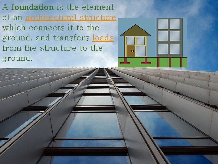
A foundation is the element of an architectural structure which connects it to the ground, and transfers loads from the structure to the ground.
Foundations are designed to have an adequate load capacity depending on the type of subsoil supporting the foundation by a geotechnical engineer, and the footing itself may be designed structurally by a structural engineer The primary design concern are bearing capacity and settlements.
Functions of Foundations 1. Reduction of load intensity Foundation distributes the load of the superstructure, to a larger area so that the intensity of the load at its base does not exceed the safe bearing capacity of the sub soil. 2. Provision of level surface Foundation provides leveled and hard surface over which the super structure can be built. 3. Even distribution of load Foundations distribute the non-uniform load of the superstructure evenly to the sub soil.
4. Lateral Stability It anchors the superstructure to the ground, thus imparting t lateral stability to the super structure. The stability of the bui against sliding and overturning due to horizontal forces is incr due to foundations 5. Protection against soil movements Special foundation measures prevents or minimizes the distr superstructure due to the expansion or contraction of the sub because of moisture movement. 7. Safety against undermining It provides the structural safety against underming or scourin burrowing animals and flood water.
bearing capacity is the capacity of soil to support the loads applied to the ground. The bearing capacity of soil is the maximum average contact pressure between the foundation and the soil which should not produce shear failure in the soil. Ultimate bearing capacity is theoretical maximum pressure which can be supported without failure; allowable bearing capacity is the ultimate bearing capacity divided by a factor of safety.
Factors affecting the bearing Capacity of the soil. 1. Physical features of the foundation namely, type of foundation, size and shape of the foundation, depth of foundation below the ground level and rigidity of the structure. 2. Type of soil and its physical properties such as density and shear strength. 3. Position of ground water table, 4. Allowable total and differentiable settlements.
Ultimate bearing capacity: It is the gross pressure at the base of the foundation at which the soil fails at shear. ULBC of soil can be determined by Plate Load test or standard penetration test. In plate load test, a square rigid steel is loaded Gradually and the settlement of the soil is Measured. Ultimate load bearing capacity= Maximum load ----------Area of the plate
Safe bearing capacity: Safe bearing capacity of the soil is defined as the maximum load per unit area that the soil can carry safely without the risk of failure. It is used for the design of foundation and up to this load there is no settlement for the soil. Safe bearing capacity= Ultimate bearing capacity -----------------Factor of safety
Foundation may be broadly classified as shallow or deep foundation, depending on the depth of the loadtransfer member below the super structure and the type of transfer load mechanism. When the depth of foundation is less than or equal to its width it is a shallow foundation. when the depth is equal to or greater than the width it is a deep foundation.
Shallow Foundations Shallow foundations are classified into : v v v Strip footing or Continuous footing Spread or Isolated or Pad Footing Combined footing Strap footing Mat foundation or Raft foundation
1. Strip Footing Or Continuous Footing A strip footing also known as continuous footing is generally provided for a load-bearing wall or for a row of columns which are so closely spaced that their spread footing overlap or nearly touch each other. In such a case , it is more economic to provide a strip footing than to provide a number of spread footing in one line. 2. S p r e a d o r I s o l a t e d o r P a d F o o t i n g Spread ( Isolated or Pad ) Footing provide to support an individual column. This is the most common type of foundation. The base of these footings are kept enlarged or spread to provide individual support. A spread footing is circular square or rectangle slab of uniform Thickness.
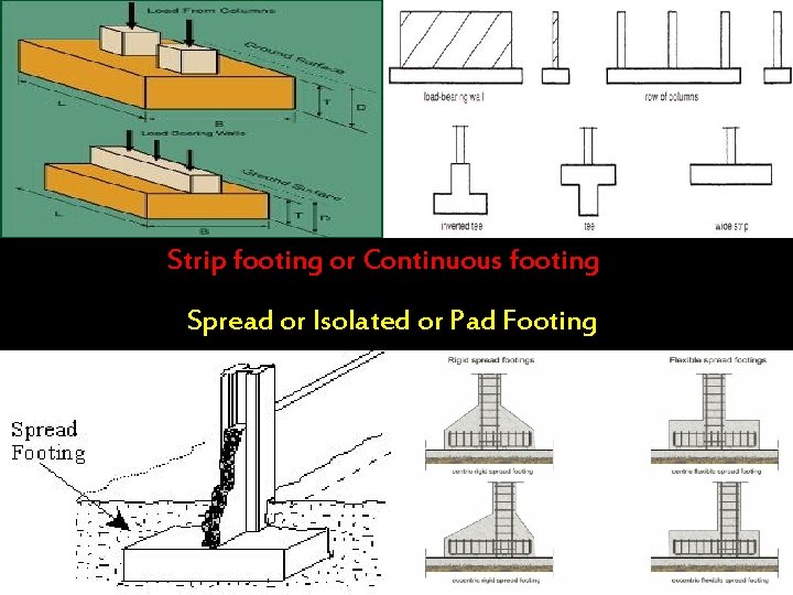
Strip footing or Continuous footing Spread or Isolated or Pad Footing
3. Combined Footing A spread footing which supports two or more columns is termed as combined footing It is used when two adjacent columns are so close to each other that their individual footing may overlap. A combined footing is also provided when the property line is so close to the column that a spread footing is eccentrically loaded when kept entirely within the property lime and by combining it with that of an interior column , the load is evenly distributed. A combined is rectangular in shape if both columns carry equal
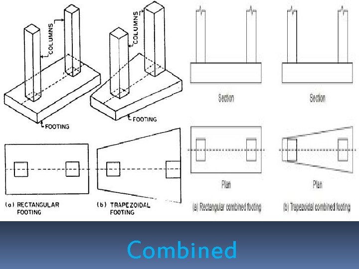
Combined
4. Strap footing A strap ( or Cantilever ) footing consist of two isolated footing connected with a structural strap or lever. The strap connects the two footing such that they behave as one unit and the strap is designed as a rigid beam. The individual footing are so designed that their combined line of action passes through the resultant of total load. A strap footing may be used where the distance between columns are so great that trapezoidal footing becomes quite narrow. Strap is not connected to the soil , so that no pressure is transferred to the soil. A strap footing is more economical than a combined footing when the allowable soil pressure is relatively high and the distance between the columns are large. The function of strap beam is to transfer the load of heavily loaded outer column to the inner one.
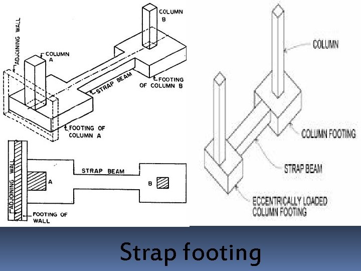
Strap footing
5. Mat foundation or Raft foundation is a combined footing supporting a number of columns and walls under the entire structure or a large pert of the structure. A mat is required when the allowable soil pressure is low or where the column and walls are so close that the individual footing would over lap or nearly touch each other. Mat foundations are useful in reducing the differential settlements on non-homogeneous soils or where
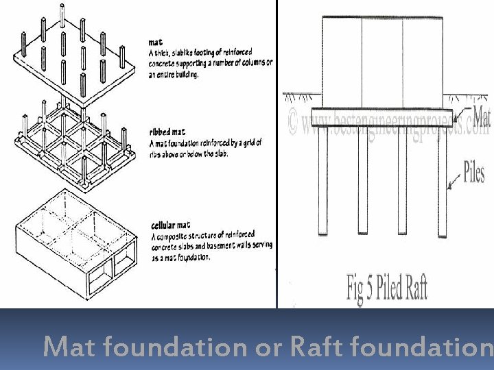
Mat foundation or Raft foundation
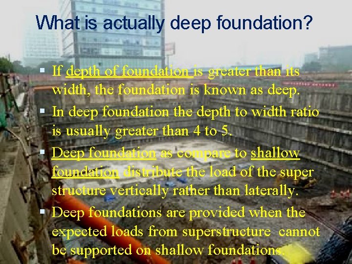
What is actually deep foundation? If depth of foundation is greater than its width, the foundation is known as deep. In deep foundation the depth to width ratio is usually greater than 4 to 5. Deep foundation as compare to shallow foundation distribute the load of the super structure vertically rather than laterally. Deep foundations are provided when the expected loads from superstructure cannot be supported on shallow foundations.
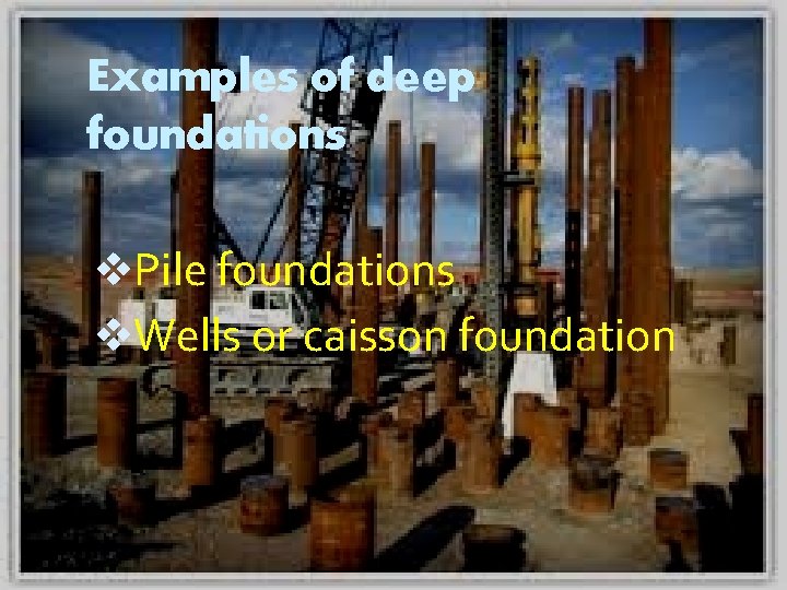
Examples of deep foundations v. Pile foundations v. Wells or caisson foundation
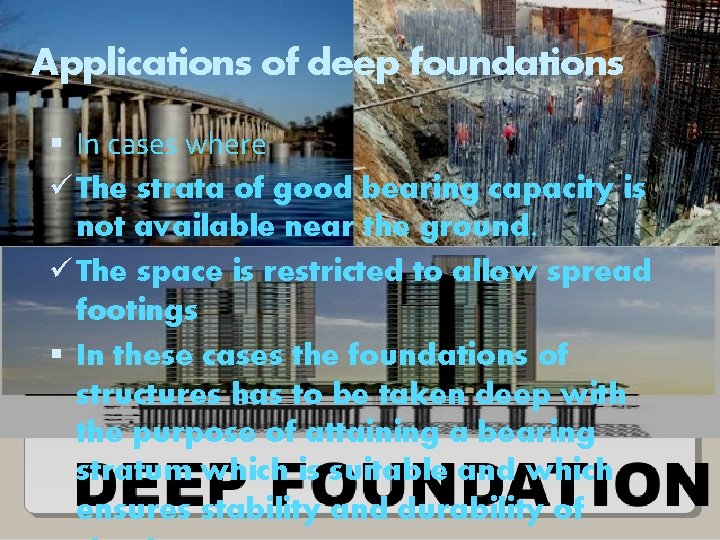
Applications of deep foundations In cases where ü The strata of good bearing capacity is not available near the ground. ü The space is restricted to allow spread footings In these cases the foundations of structures has to be taken deep with the purpose of attaining a bearing stratum which is suitable and which ensures stability and durability of
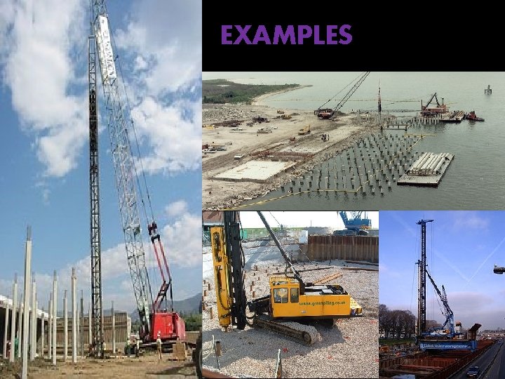
EXAMPLES
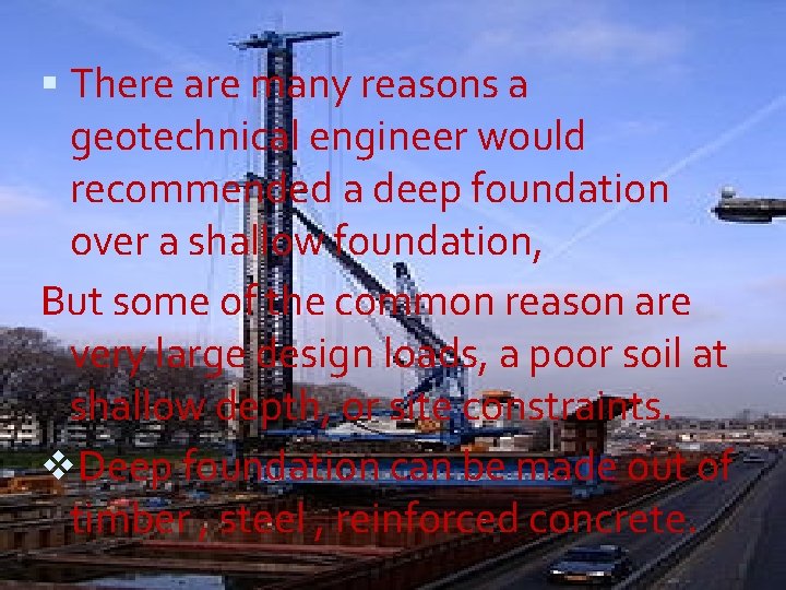
There are many reasons a geotechnical engineer would recommended a deep foundation over a shallow foundation, But some of the common reason are very large design loads, a poor soil at shallow depth, or site constraints. v. Deep foundation can be made out of timber , steel , reinforced concrete.
CLASSIFICAION OF PILES BASED ON MATERIAL
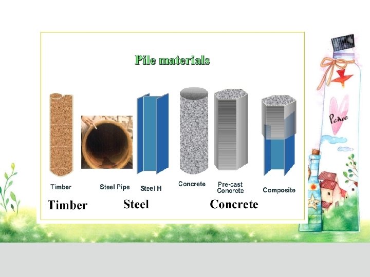
1. TIMBER PILES 2. STEEL PILES 3. CONCRETE PILES 4. COMPOSITE PILES
1. TIMBER PILES Timber piles are made of tree trunks driven with small end as a point. Lengths of piles are varying from 9 to 20 m and load carrying capacity is 80 to 240 k. N
2. STEEL PILES Steel piles are suitable for handling and driving in long lengths. Their relatively small cross sectional area combined with their high strength makes penetration easier in firm soil. They can be easily cut off or joined by welding
3. CONCRETE PILES Concrete piles can be divided into two types: a. Pre-cast piles b. Cast in situ piles
a) Pre cast piles They are manufactured in factory other than construction site. They are produced in short length in one meter intervals between 3 and 13 meters. Pre cast piles may be square, triangle, circle or octagonal section. They are pre cast so that can be easily connected together in order to reach the required length. They must be reinforced to withstand
b)Cast in situ piles Cast -in -situ piles are those which are cast in position inside the ground. Since the cast- in- situ piles are not subjected to handling or driving stresses , it is not necessary to reinforce the pile in ordinary cases where the pile is completely submerged in the soil.
Cast -in –situ piles can be divided into two types: 1. Cased cast in situ piles 2. Uncased cast in situ piles
1. Cased cast in situ piles: If the casting of the pile is permanently left in place inside the ground along the core , then it is known as cased cast in situ piles. Vaious types are: a. Raymond piles b. Lorenz piles c. Tubex piles d. Button bottom piles
2. Uncased cast in situ piles: If the casing is withdrawn after placing the concrete , then it is known as uncased cast in situ piles. Various types are: a. Simplex piles b. Vibro piles c. Pedestal piles d. Under reamed piles
4. COMPOSITE PILES Combination of different materials in the same of pile. As indicated earlier , part of timber pile which is installed above ground water would be vulnerable to insect attack and decay. To avoid this , concrete or steel pile is used above the ground water level, whilst wood pile is installed above the ground water level.
Based on method of installation: 1. CAST IN SITU PILES 2. DRIVEN PILES
4. COMPOSITE PILES I • It is the combination of different materials in the same of pile. • Concrete or steel pile is used above the ground water level , whilst wood pile is installed under the ground water level to prevent insect attack or decay
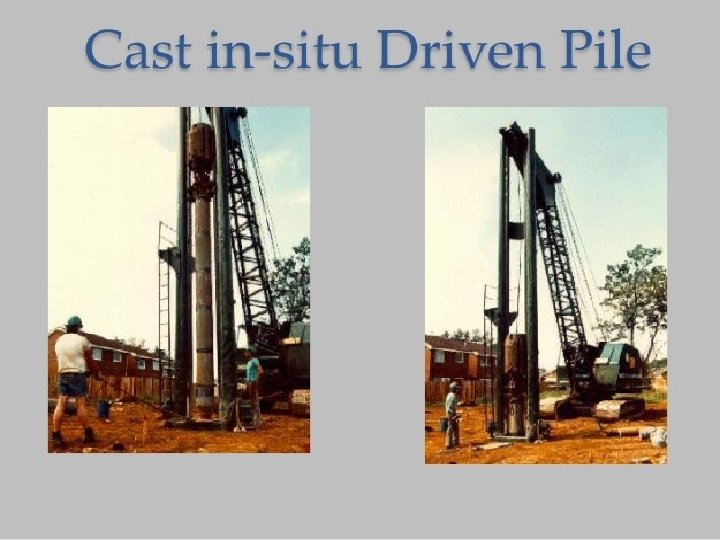
Based on method on installation I. Driven pile II. Cast-in-situ piles III. Driven and cast-in-situ pile
PIER FOUNDATIONS: They support structural loads at a number of distinct points , not continuously • Pier foundation are used when the hard strata are available at reasonable depth and load to be transmitted is large • It is a vertical shaft which is filled with inert material • Mainly used as foundation of bridges, towers etc. •
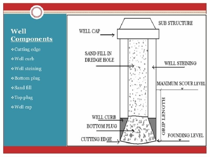
WELL FOUNDATIONS • Deep foundation generally provided below water level for bridges • Cassions of well have been in use for foundation of bridges and other structures Well cassions are three types: 1. Box cassion 2. Open cassion 3. Pneumatic cassion
H T . . . D N E E
- Slides: 45