Foundations Definition Foundations Footings The structural member that

Foundations
 : The structural member that discharges the load of")
Definition Foundations ( Footings) : The structural member that discharges the load of the building into the ground Slab This Beam Column structural member is constructed under the surface of the ground. Foundations Ground
 Continuou s Strap")
Types of Foundations Deep Single Combined Shallow Raft (mat) Continuou s Strap

Types of Foundations Deep Foundations: This type is needed when bearing capacity of shallow soil formation is poor and structure loads are heavy. A deep foundation is used to transfer a load from a structure through an upper weak layer of soil to a stronger deeper layer of soil. In addition to supporting structures, piles are also used to anchor structures against uplift forces and to assist structures in resisting lateral and overturning forces. This type gains its strength in supporting heavy loads from frictional forces developed between the surrounding soil and the surface area of the foundation Example: Piles , Piers

Types of Foundations

Types of Foundations

Types of Foundations Shallow Foundations: Most common type of foundation used when firm soil strata is not too deep and soil engineering properties are suitable regardless of the load transferred by the foundations to the ground. Bearing Capacity: Strength of soil (load/area) Example: kg/cm² , t/m² , N/mm² , Ib/ft², etc…

Types of Shallow Foundations 1. Single Footing: it is an isolated footing that supports one column. Shapes: Square, rectangle or circular; it depends on the cross section of column and space available.

Types of Shallow Foundations 1. Single Footing:

SINGLE FOOTING

Types of Shallow Foundations 2. Combined Footing: it is a footing that supports more than one column, provided all columns share the same axis. Why is it used? 1. 2. Space between columns is short. Loads on columns are high and bearing capacity of soil is low → causes over lapping

Types of Shallow Foundations 2. Combined Footing:

Types of Shallow Foundations 2. Combined Footing:

Types of Shallow Foundations 2. Combined Footing:

Types of Shallow Foundations 2. Combined Footing:

COMBINED FOOTING when the two column are so close to each other that their single footings would overlap.

COMBINED FOOTING Distance between footings is very small

COMBINED FOOTING When one column is close to a property line or sewer pipe, the Centre of gravity of the column will not coincide with footing. In such cases, it is necessary to provide combined this footing with that of the adjacent internal column ( p 1>p 2). P 1>P 2

Types of Shallow Foundations 3. Wall Footing: this strip footing is designed mainly to supports a wall, but any columns on the wall axis will share the same footing.

Types of Shallow Foundations 3. Wall Footing:

WALL FOOTING
 Footing: Raft foundation: is a thick")
Types of Shallow Foundations 4. Mat (Raft) Footing: Raft foundation: is a thick concrete slab reinforced with steel which covers the entire contact area of the structure like a thick floor.
 Footing: Why is it used? 1.")
Types of Shallow Foundations 4. Mat (Raft) Footing: Why is it used? 1. Mat foundations become a must when structure loads are high, bearing capacity of soil is low and soil highly compressible. 2. Total area of individual footing ΣAf > 60% of plan area of structure; it is more economical and safer to choose mat foundation
 Footing:")
Types of Shallow Foundations 4. Mat (Raft) Footing:

Chosen the Most Economical Safe Foundation Depends on Major properties of soil Bearing capacity; Strength of soil (load/area); kg/cm² , t/m² , N/mm² , Ib/ft², etc… Compressibility Expansive clay Load on Structure Space between axis of columns

FOUNDATIONS

DESIGN OF SINGLE FOOTING 0. 1*P P

DESIGN OF SINGLE FOOTING Find the depth : Shear Wide shear Choose the maximum “d” Punching shear

DESIGN OF SINGLE FOOTING Wide shear : q Shaded area Resisting area

DESIGN OF SINGLE FOOTING OR q

DESIGN OF SINGLE FOOTING Punching shear
cm")
DESIGN OF SINGLE FOOTING Example : P= 218 t , Dimensions of column (50*50)cm B. C = 1. 5 kg/ Find Area of footing ?

DESIGN OF SINGLE FOOTING Solution:

DESIGN OF SINGLE FOOTING Shaded area

DESIGN OF SINGLE FOOTING q Shaded area Resisting area

DESIGN OF SINGLE FOOTING d. Punching
 Maximum moment on the face of the column")
DESIGN OF SINGLE FOOTING Moment (y-axis) Maximum moment on the face of the column

DESIGN OF SINGLE FOOTING q*4 F = q * 4 * 1. 75 M= q * 4 * 1. 75/2 M= 14. 98 * 4*1. 75 * 1. 75/2 M= 91. 7525 t. m F

Example 2 : column = 30 x 60 cm Load = 240 KN B. C =20 t/m Fv (WB) = 15 t/m Fv (ps) = 30 t/m 1. Find Ad A = 1. 1 P = 1. 1* 240 = 13. 2 m 2 B. C 20 choose the shape of footing : we cannot use square footing since the dimensions are controlled by the property lines. A= =3. 63 m x

There fore , we tend to choose rectangular footing 1. 5 * 2 =3 m 3 * 2 =6 m so lets take B= 3 m L= A =4. 4 m B 4. 4 =2. 2 < 3 m … OK. 2 4. 4 m 2. q = 1. 1 P = 1. 1* 240 = 20 t/m 2 Ad 13. 2
(2.")
A. Wide beam shear : 1 - short direction : shaded area = (3)(2. 2 -0. 3 -d)= (5. 7 -3 d) m shear force =(5. 7 -3 d) * 20 = (114 -60 d) ton 1 Fv = shear force = 15 = 114 -60 d resisting area 3 d d =1. 1 m 2 - long direction : shaded area = (4. 4)(1. 5 -0. 15 -d)= (5. 94 - 4. 4 d ) m shear force = (5. 94 - 4. 4 d ) *20 = (118. 8 - 88 d) ton 2 Fv = 118. 8 - 88 d =15 d= 0. 77 m 44 d 3 m
 – ( (0. 6+d)(0. 3+d)")
3 - Punching shear Shaded area = (4. 4*3) – ( (0. 6+d)(0. 3+d) ) = (13. 02 - 0. 9 d -d ) m Shear force = (13. 02 -0. 9 d - d ) *20 = (260. 4 -18 d -20 d ) ton Fv = 260. 4 – 18 d – 20 d = 30 1. 2 d + 4 d d= 1. 13 m … punching shear controls d = 1. 13 m d = 1. 15 m 3 Shaded area = 13. 02 -0. 9 d –d Resisting area = 2 * (d)(0. 3+ d) + 2*(d)(0. 6+d) =1. 8 d + 4 d

y 4 - maximum bending moments 1. M y-y = (3*1. 9* 1. 9 ) *20 = 108. 3 ton-m 2 2. M x-x =(4. 4* 1. 35 ) *20 = 80. 2 ton-m 2 1. 35=3 – 0. 15 2

DESIGN OF COMBINED FOOTING which has a rectangular shape and carry two columns of unequal loads p 1 p 2

DESIGN OF COMBINED FOOTING •

DESIGN OF COMBINED FOOTING d • v d d B

Punching shear c+d DESIGN OF COMBINED FOOTING d d+c
 B’= 1. 5 d+c 2 • c")
DESIGN OF COMBINED FOOTING Moment (short direction) B’= 1. 5 d+c 2 • c 1 B’ B’ c 2 c 1 B

Example : C 1= 40 x 40 cm C 2 =50 X 50 cm DL =700 KN LL = 700 KN DL =900 KN LL =1200 KN Total service load = 1400 KN. Total service load =2100 KN Space between columns = 3 m (center to center) B. C = 220 KN/m 2 Fv(wb)= 600 KN/m 2 , fv(p. s) =1200 KN/m 2 Sol. : 1. A = 1. 1* P = 1. 1(1400+2100) = 17. 5 m 2 B. C 220

1. 2. R = P = 3500 KN 3. Find location of R : MR = 0 = 1400(3 -X)- 2100 X X =1. 2 m 4. Choose L : 1. 2. 3. 4. Add 0. 6 to the right. Add 0. 2 to the left to cover the column Add 0. 2 also to the right to maintain the C. G Add 1 m for both sides to put a distance from the face of C 1 in order to resist punching. finally L = 6 m.

5. Find B : B = A = 17. 5 = 2. 92 m L 6 B=3 m check : B = 3 = 1 OK. L 6 2 6. Design Area : Ad = 6 x 3 = 18 m 2 7. Soil pressure = q = 1. 1 p = 214 KN/m 2 18 q = 1. 1 p = 641. 4 KN/m L OR q =qx. B

1. 1*400 KN 1. 1*2100 KN 8. Draw shear and B. M diagrams : q =6417 KN/m find ehe load of zero shear : x from trigonometry " "ﺗﺸﺎﺑﻪ ﺍﻟﻤﺜﻠﺜﺎﺕ 769. 96 = 1155. 14 x 3 -x x=1. 2 m. Check for wide beam shear : Find Vmax @ d : 1. 8 m Vmax@d = 1155. 14 770. 4 x 1155. 14 = Vmax @d. 1. 8 -(d-0. 25) Vmax @d = 994. 939 -641. 89 d 3 m 1. 2 m d 769. 96 1154. 86 Resisting area = B*d = 3 d Fv =994. 939 - 641. 89 d =600 3 d d= 0. 41 m take d=0. 45 m. 462. 024 1039. 67 B. M= 1039. 67 KN. m Long direction

Check for punching shear : 1155. 14 = V@ d/2 1. 8 -(d/2 +0. 25) 1. 8 V@d/2 = 2079. 252 - 577. 57 d -288. 785 V @d/2 = 994. 704 – 320. 872 d Resisting area = (d+0. 5)*d *4 = (d 2 + 0. 5 d) *4 Fv = 994. 704 – 320. 872 d = 1200 4(d 2 + 0. 5 d) d = 0. 253 m d= 0. 3 m d of footing = 0. 45 from W. B shear.

Find the moment in the short direction. M = P. Arm P = (1. 5 -0. 25)* (1. 175)*q = 962. 5 q = (1. 1)(1200) = 655. 32 KN/m 2 3 * 1. 175 Arm = 1. 25 = 0. 625 m 2 M = 601. 6 KN-m

DESIGN OF WALL FOOTING

DESIGN OF WALL FOOTING d – Wide beam shear Wall d L=1 m B

DESIGN OF WALL FOOTING Moment: q In short direction : Wall q In long direction : We use As minimum L=1 m B

DESIGN OF WALL FOOTING Example : load on wall = 20 t/m B. C = 20 kg/ Find Area of footing and dimensions?

DESIGN OF WALL FOOTING Wall d L=1 m 1. 1 m
 :")
DESIGN OF WALL FOOTING M (short) :

DESIGN OF TRAPEZOIDAL FOOTING which be used to carry two columns of unequal loads when distance outside the column of the heaviest load is limited.

DESIGN OF TRAPEZOIDAL FOOTING R P 1 P 2 Find X C 1 X C 2 D D’ C

DESIGN OF TRAPEZOIDAL FOOTING Example : P 1= 100 t , Dimensions of column (60*60)cm P 2=80 t , Dimensions of column (50*50)cm B. C = 17. 6 kg/ Find Area of footing and dimensions? L

DESIGN OF TRAPEZOIDAL FOOTING 80 t 100 t 1. 33 2. 13 Property line

DESIGN OF TRAPEZOIDAL FOOTING Take : L=5 m

STRAP FOOTING D>4 m
. I (strap ) > I (footing).")
STRAP FOOTING Not contact with soil. Massive (rigid). I (strap ) > I (footing).

ECCENTRICITY

Eccentricity in foundations is due to either limitation of space available for footing or to bending moment transmitted by columns especially if we have frame systems, cause overturning. P P P M M X M=M e=M P M = M + PX e = M + PX P ex ey A. Uniaxial B. Biaxial C. Moment couple
 P B/2 Max comp. Max tension (in")
Y P (means compression in the foundation) P B/2 Max comp. Max tension (in compression zone) x B/2 (in tension zone) L/2 Y L/2
 + 0. 1 P < B. C")
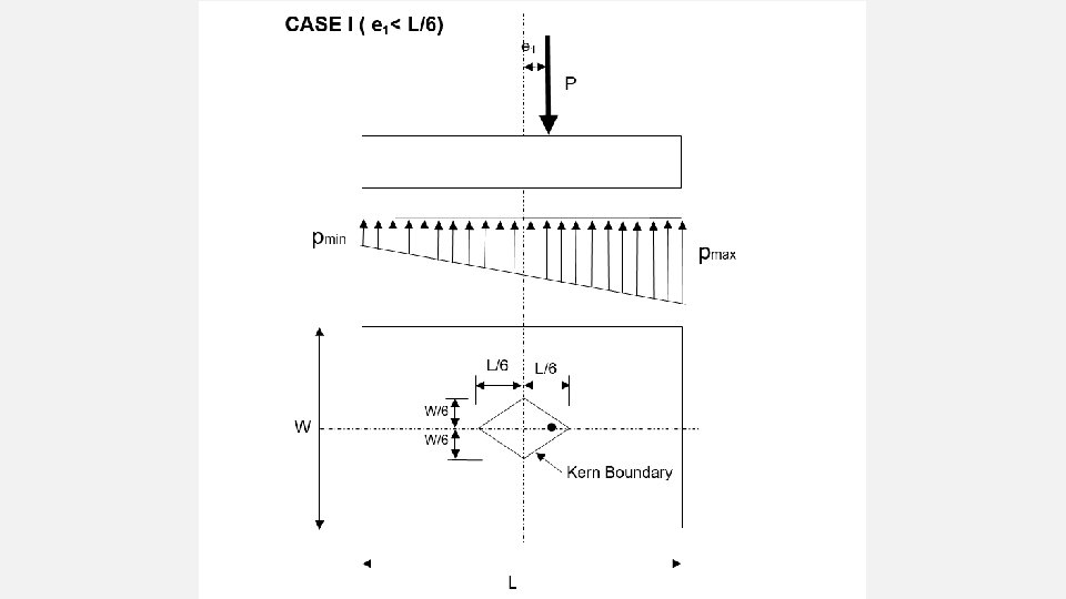
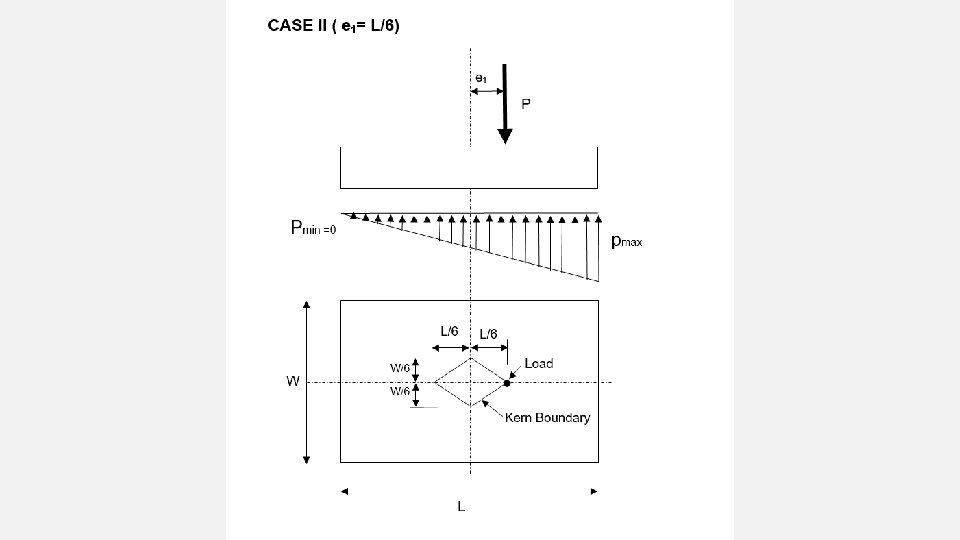
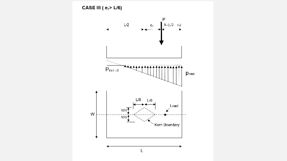
σA = P (1+ 6 e ) + 0. 1 P < B. C A L A SAFE σB = P (1 - 6 e ) + 0. 1 P < B. C and +ve A L A But if σ = -ve the stress will be tensile so the control between the RC footing and soil is lost ! (fail) To ensure that there is no tensile stresses e must be within L from y axis. 6 6 e < 1 L e= L (max limit) 6

UNIAXIAL ECCENTRICITY CASES:

Example : For 4 x 2 single footing that supports a column with 80 ton load, B. C = 15 t/m 2. Check the safety of footing against eccentricity. M = (80)(0. 4) = 32 t. m e = 0. 4 m σA = P (1+ 6 e ) + 0. 1 P A L A = 80 (1 + 6(0. 4) ) + 0. 1*80 = 17 t/m 2 > 15 t/m 2 8 4 8 σB = P (1 - 6 e ) + 0. 1 P = 5 t/m 2 < B. C and +ve A L A not safe. 0. 4 m

EX : for the shown single footing 3 x 4 m , p= 150 ton , B. C = 15 t/m 2 A. check the safety against eccentricity. B. Draw soil pressure on the footing. A. e = 1 m = M P σ = P (1+ 6 e ) + 0. 1 P A L A = 32. 5 t/m 2 > B. C (not safe) σ = P (1 - 6 e ) + 0. 1 P A L A 1. 5 m = -5 t/m 2 < BC but –ve (not safe) 1 m 1 m

B. P -5*3 = -15 t/m Soil pressure 3*32. 5 = 97. 5 t/m
- Slides: 78